Advertisement
Quick Links
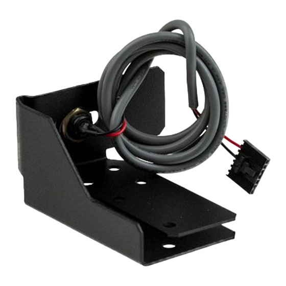
CARTON INVENTORY
Reset switch bracket, washer head screws (3) #10-32X5/8",
washer nuts (3) #10-32, reset switch with cable, label, plastic
grommet and cable ties (3).
INSTALLATION
1. Disconnect power to operator.
2. Remove the cover from the operator.
3. Assemble reset switch by installing screws (3) and nuts (3)
to the mounting bracket (Figure 1).
4. Attach the assembly to the operator leg with (3) screws
5. against the top edge and the front flange to the front edge of
the leg (Figure 2).
2. Remove the cover from the operator.
3. Assemble reset switch by installing screws (3) and nuts (3)
to the mounting bracket (Figure 1).
4. Attach the assembly to the operator leg with (3) screws
against the top edge and the front flange to the front edge of
the leg (Figure 2).
FIGURE 2
Wire through this hole if
connected to board.
Wire through here if not
connected to board.
Other (2) screws are against
the top edge of the leg.
CSW200
MODEL K71-33445
FOR USE WITH OMNI BOARD
UPGRADE FOR CSW200
To prevent possible SERIOUS INJURY or DEATH from
electrocution, disconnect electric power to operator BEFORE
installing.
ALL electrical connections MUST be made by a qualified
individual.
WARNING: This product can expose you to chemicals
including lead, which are known to the State of
California to cause cancer or birth defects or other
reproductive harm. For more information go to
www.P65Warnings.ca.gov
FIGURE 1
Washer Nuts
Washer Head Screws
CSW200
Wire through this hole if
connected to board.
All (3) screws are against the top edge
of the leg then tighten all screws.
This flange is against
the front edge of the leg.
1
RESET SWITCH
AND SL3000
Washer Nuts
Washer Head Screws
SL3000
SL3000
Advertisement

Related Manuals for Chamberlain K71-33445


Summary of Contents for Chamberlain K71-33445
- Page 1 RESET SWITCH MODEL K71-33445 FOR USE WITH OMNI BOARD UPGRADE FOR CSW200 AND SL3000 CARTON INVENTORY Reset switch bracket, washer head screws (3) #10-32X5/8”, washer nuts (3) #10-32, reset switch with cable, label, plastic To prevent possible SERIOUS INJURY or DEATH from grommet and cable ties (3).
- Page 2 5. Connect the wires for the reset switch referring to the 5. Connect the wires for the reset switch referring to the FIGURE 3 instructions appropriate to the operator instructions appropriate to the operator. SL3000UL AND CSW200 (STANDARD OPERATORS): • Route the wires into the electrical box and plug the Plug Reset SL3000UL AND CSW200 (STANDARD Switch Connector...
- Page 3 Line Up Template with Lower Right Corner of Access Door Drill 7/8" Hole for Reset Switch Access SWING GATE TEMPLATE CSW200 Base of Operator Drill 7/8" Hole for Reset Switch Access Make Flush With Padlock Loop SLIDE GATE TEMPLATE SL3000 Base of Operator...
- Page 4 © 2006, LiftMaster 01-33446B All Rights Reserved...