Table of Contents
Advertisement
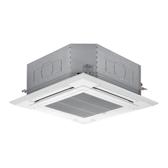
SPLIT-TYPE AIR CONDITIONERS
SERVICE MANUAL
Series PLY
Indoor unit
[Model Name]
[Service Ref.]
PLY-P18BA.TH
PLY-P18BA
PLY-P24BA.TH
PLY-P24BA
PLY-P30BA.TH
PLY-P30BA
PLY-P36BA.TH
PLY-P36BA
PLY-P42BA.TH
PLY-P42BA
PLY-P48BA.TH
PLY-P48BA
INDOOR UNIT
Model name
indication
WIRELESS REMOTE
CONTROLLER
ON/OFF
TEMP
WIRED REMOTE
CONTROLLER
TEMP.
ON/OFF
(Option)
REVISED EDITION-A
Revision:
• Added
• Some descriptions has
• Please void OCH551.
Note:
• This manual describes ser-
• RoHS compliant products
CONTENTS
1. REFERENCE MANUAL .................................. 2
2. SAFETY PRECAUTION .................................. 3
3. PARTS NAMES AND FUNCTIONS ................ 4
4. SPECIFICATIONS ......................................... 12
5. NOISE CRITERION CURVES ....................... 14
6. OUTLINES AND DIMENSIONS ..................... 15
7. WIRING DIAGRAM ........................................ 16
8. REFRIGERANT SYSTEM DIAGRAM ........... 17
9. TROUBLESHOOTING ................................... 18
10. SPECIAL FUNCTION .................................... 33
11. DISASSEMBLY PROCEDURE ...................... 40
PARTS CATALOG (OCB551)
April 2014
No. OCH551
PLY-P42BA.TH and
PLY-P48BA.TH in
REVISED EDITION-A.
been modified.
vice data of the indoor units
only .
have <G> mark on the
spec name plate.
Advertisement
Table of Contents

Related Manuals for Mitsubishi Electric Mr.Slim PLY-P18BA.TH


Summary of Contents for Mitsubishi Electric Mr.Slim PLY-P18BA.TH
-
Page 1: Table Of Contents
SPLIT-TYPE AIR CONDITIONERS April 2014 No. OCH551 REVISED EDITION-A SERVICE MANUAL Series PLY Indoor unit [Model Name] [Service Ref.] Revision: PLY-P18BA.TH • Added PLY-P42BA.TH and PLY-P18BA PLY-P48BA.TH in REVISED EDITION-A. PLY-P24BA.TH • Some descriptions has PLY-P24BA been modified. PLY-P30BA.TH • Please void OCH551. PLY-P30BA Note: •... -
Page 2: Reference Manual
REFERENCE MANUAL 1-1. OUTDOOR UNIT’S SERVICE MANUAL Service Ref Service Manual No. OCH552 SUY-KA18/24/30/36VA.TH OCB552 PUY-P42/48VKA.TH(-T) OCH558 PUY-P42/48YKA.TH(-T) OCB558 1-2. TECHNICAL DATA BOOK Series (Outdoor unit) Data Book No. SUY-KA▪VA.TH OCS27 PUY-P▪VKA.TH OCS29 PUY-P▪YKA.TH OCH551A... -
Page 3: Safety Precaution
SAFETY PRECAUTION CAUTIONS RELATED TO NEW REFRIGERANT Cautions for units utilising refrigerant R410A Use a vacuum pump with a reverse flow check Use new refrigerant pipes. valve. In case of using the existing pipes for R22, be careful with Vacuum pump oil may flow back into refrigerant cycle and the followings. -
Page 4: Parts Names And Functions
Unit Gravimeter [3] Service tools Use the below service tools as exclusive tools for R410A refrigerant. Tool name Specifications Gauge manifold · Only for R410A · Use the existing fitting specifications . (UNF1/2) · Use high-tension side pressure of 5.3MPa·G or over. Charge hose ·... - Page 5 3-2. WIRED REMOTE CONTROLLER <PAR-21MAA> “Sensor” indication Display Section Displays when the remote controller sensor is used. Day-of-Week For the purpose of explanation, Shows the current day of the week. all parts of the display are shown. During actual operation, only Time/Timer Display the relevant items will be lit.
- Page 6 3-3. WIRELESS REMOTE CONTROLLER CHECK TEST RUN display CHECK and TEST RUN display indicate that the unit is being checked or test-run. MODEL SELECT display Blinks when model is selected. display Lights up while the signal is transmitted to the indoor unit when the button is pressed. display SET TEMP.
- Page 7 3-4. WIRED REMOTE CONTROLLER <PAR-31MAA> (Option) Wired remote controller function The functions which can be used are restricted according to each model. : Supported : Unsupported Function PAR-31MAA PAR-21MAA Body Product size H × W × D (mm) 120 × 120 × 19 120 ×...
- Page 8 Room Set temp. Cool Auto Mode Temp. The main display can be displayed in two different modes: "Full" and "Basic". The initial setting is "Full". To switch to the "Basic" mode, change the setting on the Main display setting. <Full mode> <Basic mode>...
- Page 9 Menu structure Press the button. MENU Main menu Move the cursor to the desired item with the buttons, and press the button. SELECT Vane · Louver · Vent. (Lossnay) High power Timer On / Off timer Auto-Off timer Filter information Error information Weekly timer Energy saving...
- Page 10 Main menu list Setting and display items Setting details Vane · Louver · Vent. Use to set the vane angle. (Lossnay) • Select a desired vane setting from five different settings. Use to turn ON / OFF the louver. • Select a desired setting from "ON" and "OFF." Use to set the amount of ventilation.
- Page 11 Setting and display items Setting details Initial setting Display Make the settings for the remote controller related items as necessary. details Clock: The factory settings are "Yes" and "24h" format. Temperature: Set either Celsius (°C) or Fahrenheit (°F). Room temp. : Set Show or Hide. Auto mode: Set the Auto mode display or Only Auto display.
-
Page 12: Specifications
SPECIFICATIONS Service Ref. PLY-P18BA.TH Cooling Mode Single phase, 50Hz, 220-240V/Single phase, 60Hz, 220V Power supply (phase, cycle, voltage) 0.05 Input 0.36 Running current Munsell 6.4Y 8.9/0.4 External finish (Panel) Heat exchanger Plate fin coil Fan (drive) o No. Turbo fan (direct) o 1 Fan motor output 0.050 12-13-14-16... - Page 13 Service Ref. PLY-P30BA.TH Cooling Mode Single phase, 50Hz, 220-240V/Single phase, 60Hz, 220V Power supply (phase, cycle, voltage) 0.14 Input 0.94 Running current Munsell 6.4Y 8.9/0.4 External finish (Panel) Heat exchanger Plate fin coil Fan (drive) o No. Turbo fan (direct) o 1 Fan motor output 0.120 20-22-25-28...
-
Page 14: Noise Criterion Curves
NOISE CRITERION CURVES PLY-P18BA.TH PLY-P24BA.TH NOTCH SPL(dB) LINE NOTCH SPL(dB) LINE High High Medium1 Medium1 Medium2 Medium2 NC-70 NC-70 NC-60 NC-60 NC-50 NC-50 NC-40 NC-40 NC-30 NC-30 APPROXIMATE APPROXIMATE THRESHOLD OF THRESHOLD OF HEARING FOR HEARING FOR NC-20 NC-20 CONTINUOUS CONTINUOUS NOISE NOISE... -
Page 15: Outlines And Dimensions
OUTLINES AND DIMENSIONS PLY-P18BA.TH PLY-P24BA.TH PLY-P30BA.TH PLY-P36BA.TH PLY-P42BA.TH PLY-P48BA.TH Unit: mm Ceiling hole 20~45 20~45 860~910 Detail connecting of branch duct(Both aspects) Fresh air Suspension bolt pitch intake hole Cut out hole Remote controller terminal block Indoor unit/Outdoor unit Branch duct hole connecting terminal block Branch duct hole 14-[2.8... -
Page 16: Wiring Diagram
WIRING DIAGRAM PLY-P18BA.TH PLY-P24BA.TH PLY-P30BA.TH PLY-P36BA.TH PLY-P42BA.TH PLY-P48BA.TH [LEGEND] SYMBOL NAME SYMBOL NAME INDOOR CONTROLLER BOARD FAN MOTOR CN2L CONNECTOR (LOSSNAY) VANE MOTOR CN32 CONNECTOR (REMOTE SWITCH) TERMINAL BLOCK (INDOOR/OUTDOOR CONNECTING LINE) CN41 CONNECTOR (HA TERMINAL-A) TB5,TB6 TERMINAL BLOCK (REMOTE CONTROLLER CN51 TRANSMISSION LINE) CONNECTOR (CENTRALLY CONTROL) -
Page 17: Refrigerant System Diagram
REFRIGERANT SYSTEM DIAGRAM PLY-P18BA.TH PLY-P24BA.TH PLY-P30BA.TH PLY-P36BA.TH PLY-P42BA.TH PLY-P48BA.TH Strainer (#50) Heat exchanger Refrigerant GAS pipe connection (Flare) Thermistor TH5 (Cond./ Eva.temperature) Refrigerant flow in cooling Refrigerant LIQUID pipe connection (Flare) Thermistor TH2 Pipe temperature(Liquid) Thermistor TH1 (Room temperature) Strainer (#50) Distributor with strainer (#50) OCH551A... -
Page 18: Troubleshooting
TROUBLESHOOTING 9-1. TROUBLESHOOTING <Check code display by self-diagnosis and actions to be taken for service (summary)> Present and past check codes are logged and displayed on the wired remote controller or controller board of outdoor unit. Actions to be taken for service and the trouble reoccurrence at field are summarized in the table below. Check the contents below before investigating details. - Page 19 9-2. MALFUNCTION-DIAGNOSIS METHOD BY REMOTE CONTROLLER <In case of trouble during operation> When a malfunction occurs to air conditioner, both indoor unit and outdoor unit will stop and operation lamp blinks to inform unusual stop. < Malfunction-diagnosis method at maintenance service> Wired remote controller 1 Turn on the power.
- Page 20 • Refer to the following tables for details on the check codes. [Output pattern A] Beeper sounds Beep Beep Beep Beep Beep Beep Beep OPERATION · · · Repeated INDICATOR lamp flash pattern Approx. 2.5 sec. 0.5 sec. 0.5 sec. 0.5 sec.
- Page 21 • If the unit cannot be operated properly after the test run, refer to the following table to find out the cause. Symptom Cause Wired remote controller LED 1, 2 (PCB in outdoor unit) For about 2 •For about 2 minutes following power-on,op- After LED 1, 2 are lighted, LED 2 is PLEASE WAIT minutes after...
- Page 22 9-3. SELF-DIAGNOSIS ACTION TABLE Abnormal point and detection method Countermeasure Check Code Cause Room temperature thermistor (TH1) 1 Defective thermistor 1–3 Check resistance value of thermistor. 0: ..15.0k" 1 The unit is in 3-minute resume characteristics 10: ..9.6k" prevention mode if short/open of 2 Contact failure of connector 20: ..
- Page 23 Check Code Abnormal point and detection method Countermeasure Cause Freezing protection is operating (Cooling or drying mode) (Cooling or drying mode) 1 Freezing protection (Cooling mode) 1 Clogged filter (reduced airflow) 1 Check clogs of the filter. The unit is in 6-minute resume 2 Short cycle of air path 2 Remove blockage.
- Page 24 Abnormal point and detection method Countermeasure Check Code Cause Remote controller transmission 1 Contact failure at transmission 1 Check disconnection or looseness of indoor error(E0)/signal receiving error(E4) wire of remote controller unit or transmission wire of remote controller. 1 Abnormal if main or sub remote 2 All remote controllers are set 2 Set one of the remote controllers “main”...
- Page 25 Abnormal point and detection method Countermeasure Check Code Cause Indoor/outdoor unit communication 1 Defective transmitting receiving 1-3 Turn the power off, and on again to check. error (Transmitting error) circuit of indoor controller board If abnormality generates again, replace Abnormal if “1” receiving is detected 30 indoor controller board.
- Page 26 9-4. TROUBLESHOOTING OF PROBLEMS Phenomena Cause Countermeasure (1) LED2 on indoor controller board • When LED1 on indoor controller board is also off. is off. 1 Power supply of rated voltage is not supplied to 1 Check the voltage of outdoor power outdoor unit.
- Page 27 Phenomena Cause Countermeasure (2) LED2 on indoor controller board • When LED1 on indoor controller board is also blinking. Check indoor/outdoor unit connecting wire is blinking. Connection failure of indoor/outdoor unit connecting for connection failure. wire • When LED1 is lit. 1 Miswiring of remote controller wires 1 Check the connection of remote Under twin triple indoor unit system, 2 or more indoor...
- Page 28 9-5. EMERGENCY OPERATION 9-5-1. When wireless remote controller fails or its battery is exhausted When the remote controller cannot be used When the batteries of the remote controller run out or the remote control- ler malfunctions, the emergency operation can be done using the emer- gency buttons on the grille.
- Page 29 9-6. HOW TO CHECK THE PARTS PLY-P18BA.TH PLY-P24BA.TH PLY-P30BA.TH PLY-P36BA.TH PLY-P42BA.TH PLY-P48BA.TH Parts name Check points Room temperature Disconnect the connector then measure the resistance with a tester. thermistor (TH1) (At ambient temperatures of 10 : to 30 :) Pipe temperature Normal Abnormal thermistor/liquid(TH2)
- Page 30 9-6-1. Thermistor <Thermistor Characteristic graph> < Thermistor for lower temperature > Room temperature thermistor(TH1) Thermistor for Pipe temperature thermistor/liquid(TH2) lower temperature Condenser/evaporator temperature thermistor(TH5) Thermistor R =15k" ± 3% Fixed number of B=3480 ± 2% Rt=15exp { 3480( 273+t 15 k" 10 : 9.6 k"...
- Page 31 9-7. TEST POINT DIAGRAM Indoor controller board PLY-P18BA.TH PLY-P24BA.TH PLY-P30BA.TH PLY-P36BA.TH PLY-P42BA.TH PLY-P48BA.TH LED3 CN3G CN90 Transmission Connect to the auto grille controller board (CN3G) Connect to the wireless remote (Indoor/outdoor) 13V pulse output controller board (CNB) Vane motor output (MV) CN4Y 12V pulse output i-see sensor...
- Page 32 9-8. FUNCTIONS OF DIP SWITCH AND JUMPER WIRE Each function is controlled by the DIP switch and the jumper wire on indoor controller board. The black square (■) indicates a switch position (Marks in the table below) Jumper wire ( : Short : Open) Jumper wire...
-
Page 33: Special Function
SPECIAL FUNCTION 10-1. HOW TO PERFORM THE UP/DOWN OPERATION OF THE AIR INTAKE GRILLE 10-1.1. Setting up the lowering distance of air intake grille Unit You can set up 8 different stages of lowering distance for Decorative the air intake grille according to the set up location if desired. panel Note that, as an initial setting, the decorative panel will automatically stop at 1.6 m from the ceiling level. - Page 34 10-1-2. How to perform the up/down operation using wireless remote controller Ensure that the air-conditioner is not running. Warning: • Otherwise, it may cause an injury or a failure. 1) Ensure that the air-conditioner is not running. 2) Press the "Down" button to lower the air intake grille. By default, the air intake grille will automatically stop at a lowering distance of 1.6 m from the ceiling level.
- Page 35 10-1-4. How to perform the up/down operation using wired remote controller (PAR-21MAA) Note that this function is not available for SUY model. ■ General Operation Raise or lower all the air intake grilles managed by the remote controller at the same time. Install the remote controller in a place where you can observe all the air-conditioners.
- Page 36 ■ Raise or lower the air intake grille of the specific indoor unit that you select from all that are managed by that remote controller. 1) Ensure that the air-conditioner is not running. Ensure that the indoor unit is not running. * The up/down operation mode is only available when the Warning: •...
- Page 37 10-2. OPERATION (AUTOMATIC FILTER ELEVATION PANEL: PLP-6BAJ) (1) Normal operation 1 UP/DOWN Wire 1b Air intake grille is raised/lowered by UP/DOWN UP/DOWN commands of UP and DOWN. Machine 2 Machine 1 Air intake grille does not move under the state of no-load detection or obstacle detection. Air intake grille stops automatically at the set lowering distance from the ceiling level.
- Page 38 10-3. ELECTRICAL CIRCUIT (Controller board and wiring diagram (Panel)) 10-3-1. DIP SW 22 type SW22 Panel Indoor unit (WHT) LS21 CN3G CN90 (WHT) (BLK) CN2G (BLK) CN3G (BLK) FUSE CN22 (BLU) CN2F (BLK) CNAC (WHT) CN2E LS21 (RED) CN2C CN2B (WHT) GRN/YLW (WHT)
- Page 39 10-4. TROUBLESHOOTING 11-4. TROUBLESHOOTING • Check the following points. Problem Possible Reason Corrective Action Air intake grille does not Air-conditioner is running. Stop running the air-conditioner and try again. function under operation of Power failure After recovering from power failure, try again. the wireless remote controller.
-
Page 40: Disassembly Procedure
DISASSEMBLY PROCEDURE PLY-P18BA.TH PLY-P24BA.TH PLY-P30BA.TH PLY-P36BA.TH PLY-P42BA.TH PLY-P48BA.TH OPERATING PROCEDURE PHOTOS & ILLUSTRATIONS Figure 1 1. Removing the air intake grille (1) Slide the knob of air intake grille toward the arrow to open Panel the air intake grille. Knob (2) Remove drop prevention hook from the panel. - Page 41 OPERATING PROCEDURE PHOTOS & ILLUSTRATIONS Photo 3 5. Removing the fan and fan motor (MF) (1) Remove the electrical box. (See Photo 2) Coil plate (2) Remove the bell mouth (3 screws). (See Photo 1) (3) Remove the turbo fan nut. (4) Pull out the turbo fan.
- Page 42 OPERATING PROCEDURE PHOTOS & ILLUSTRATIONS 8. Removing the pipe temperature thermistor/ liquid (TH2) Photo 8 and condenser/evaporator temperature thermistor (TH5) (1) Remove the drain pan. (See Photo 6) (2) Remove the turbo fan. (See Photo 3) (3) Remove the 2 wiring clamps. (See Photo 7) (4) Remove the coil plate (2 screws).
- Page 43 OPERATING PROCEDURE PHOTOS & ILLUSTRATIONS Photo 15 9. Removing the drain pump (DP) and float switch (FS) (1) Remove the drain pan. (See Photo 6) (2) Cut the hose band and remove the hose. (3) Remove the drain pump assembly (3 screws and 2 hooks). Float switch (4) Remove the drain pump (3 screws).
- Page 44 HEAD OFFICE : TOKYO BLDG., 2-7-3, MARUNOUCHI, CHIYODA-KU, TOKYO 100-8310, JAPAN CCopyright 2013 MITSUBISHI ELECTRIC CORPORATION New publication, effective Apr. 2014 Distributed in Apr. 2014 No.OCH551 REVISED EDITION-A Specifications are subject to change without notice. Distributed in Oct. 2013 No.OCH551...