
Related Manuals for Asus AAEON UP Squared 6000


Summary of Contents for Asus AAEON UP Squared 6000
- Page 1 UP Squared 6000 Maker Board UPN-EHL01 User’s Manual 1 Last Updated: November 29, 2021...
- Page 2 Copyright Notice This document is copyrighted, 2021. All rights are reserved. The original manufacturer reserves the right to make improvements to the products described in this manual at any time without notice. No part of this manual may be reproduced, copied, translated, or transmitted in any form or by any means without the prior written permission of the original manufacturer.
- Page 3 Acknowledgement All other products’ name or trademarks are properties of their respective owners. Microsoft® , Windows® are registered trademarks of Microsoft Corp. Intel® , Pentium® , and Celeron® are registered trademarks of Intel Corporation Intel Atom™ is a trademark of Intel Corporation ...
- Page 4 Packing List Before setting up your product, please make sure the following items have been shipped: Item Quantity UPN-EHL01 with heatsink (UP Squared 6000) Quick Start Guide If any of these items are missing or damaged, please contact your distributor or sales representative immediately.
- Page 5 About this Document This User’s Manual contains all the essential information, such as detailed descriptions and explanations on the product’s hardware and software features (if any), its specifications, dimensions, jumper/connector settings/definitions, and driver installation instructions (if any), to facilitate users in setting up their product. Users may refer to the product page at AAEON.com for the latest version of this document.
- Page 6 Safety Precautions Please read the following safety instructions carefully. It is advised that you keep this manual for future references All cautions and warnings on the device should be noted. Make sure the power source matches the power rating of the device. Position the power cord so that people cannot step on it.
- Page 7 If any of the following situations arises, please the contact our service personnel: Damaged power cord or plug Liquid intrusion to the device iii. Exposure to moisture Device is not working as expected or in a manner as described in this manual The device is dropped or damaged Any obvious signs of damage displayed on the device...
- Page 8 FCC Statement This device complies with Part 15 FCC Rules. Operation is subject to the following two conditions: (1) this device may not cause harmful interference, and (2) this device must accept any interference received including interference that may cause undesired operation.
- Page 9 China RoHS Requirements (CN) 产品中有毒有害物质或元素名称及含量 AAEON Main Board/ Daughter Board/ Backplane 有毒有害物质或元素 部件名称 铅 汞 镉 六价铬 多溴联苯 多溴二苯醚 (Pb) (Hg) (Cd) (Cr(VI)) (PBB) (PBDE) 印刷电路板 ○ ○ ○ ○ ○ ○ 及其电子组件 外部信号 ○ ○ ○ ○ ○ ○ 连接器及线材...
- Page 10 China RoHS Requirement (EN) Poisonous or Hazardous Substances or Elements in Products AAEON Main Board/ Daughter Board/ Backplane Poisonous or Hazardous Substances or Elements Hexavalent Polybrominated Polybrominated Component Lead Mercury Cadmium Chromium Biphenyls Diphenyl Ethers (Pb) (Hg) (Cd) (Cr(VI)) (PBB) (PBDE) PCB &...
-
Page 11: Table Of Contents
Table of Contents Chapter 1 - Product Specifications..................1 Specifications ......................2 Chapter 2 – Hardware Information ..................4 Dimensions ....................... 5 Jumpers and Connectors ..................6 List of Jumpers and Connectors ................8 2.3.1 PWR Button (SW1) ..................9 2.3.2 RTC (CN28) .................... - Page 12 2.3.21 Front Panel (CN65) ..................24 2.3.22 AUDIO (CN66) .................... 25 2.3.23 FAN (J1) ......................25 2.3.24 AT/ATX mode (JP7) ..................26 Connector Index ....................27 Chapter 3 – Software Installation ..................29 Linux Setup ......................30 Windows Drivers Installation ................30 Appendix A –...
-
Page 13: Chapter 1 - Product Specifications
Chapter 1 Chapter 1 - Product Specifications... -
Page 14: Specifications
Specifications System Processor Intel® Atom® X6413E / X6425RE, Celeron® N6210 (no PSE), Pentium® J6426 Processor SoC Graphics Intel® UHD Graphics for 10th Gen Intel® Processors HDMI 2.0b x 1 DP 1.2 x 1 eDP x 1 (Limited to Atom series) Audio wafer x 1 RS-232/422 x 1 (Limited to Atom series) Camera... - Page 15 System Dimension 4" x 4" (101.6mm x 101.6mm ) Memory Up to 8GB DDR4 Storage UP to 64GB eMMC Display Interface HDMI 2.0b x 1 DP 1.2 x 1 eDP x 1 (Limited to Atom series) Ethernet GbE x 1, 2.5GbE x 1 Atom: Intel®...
-
Page 16: Chapter 2 - Hardware Information
Chapter 2 – Hardware Information Chapter 2... -
Page 17: Dimensions
Dimensions Chapter 2 – Hardware Information... -
Page 18: Jumpers And Connectors
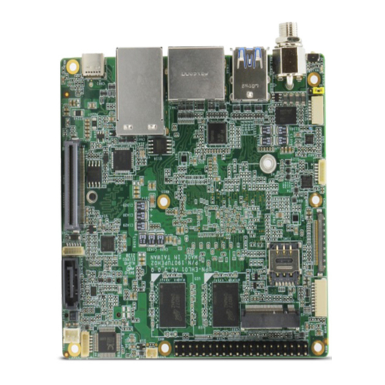
Jumpers and Connectors Top: Chapter 2 – Hardware Information... - Page 19 Bottom: Chapter 2 – Hardware Information...
-
Page 20: List Of Jumpers And Connectors
List of Jumpers and Connectors Please refer to the table below for all of the board’s jumpers that you can configure for your application Label Function PWR button CN28 CN35 M.2 Key-B Slot CN36 M.2 Key-E Slot CN38 USB Type A DUAL PORT CN39 SATA CONN CN40... -
Page 21: Pwr Button (Sw1)
Label Function AT/ATX mode 2.3.1 PWR Button (SW1) Switch Position Function SW1 1 (default) SW1 0 Power ON 2.3.2 RTC (CN28) Signal RTC_VCC Chapter 2 – Hardware Information... -
Page 22: Key-B Slot (Cn35)
2.3.3 M.2 Key-B Slot (CN35) Signal Signal Signal +3.3V +3.3V FULL_CARD_POWER_OFF# USB2_D+ W_DISABLE#1 USB2_D- USB3_RX- UIM_RST USB3_RX+ UIM_CLK UIM_DAT USB3_PX- UIM_PWR USB3_PX+ PCIE10_RXN PCIE_RXP PCIE_TXN PCIE10_TXP PLT_RST#(3.3V) PCIE_CLKREQ# PCIE_CLKN PCIE_WAKE# PCIE_CLKP Chapter 2 – Hardware Information... -
Page 23: Key-E Slot (Cn12)
Signal Signal Signal PLT_RST#(1.8V) +3.3V +3.3V +3.3V 2.3.4 M.2 Key-E Slot (CN12) Signal Signal Signal +3.3V USB2_D+ +3.3V USB2_D- CNV_BRI_RSP CNV_RGI_DT CNV_RGI_RSP PCIE_TXP CNV_BRI_DT Chapter 2 – Hardware Information... -
Page 24: Usb Type A Dual Port (Cn38)
Signal Signal Signal PCIE_TXN PCIE_RXP PCIE_RXN PCIE_CLKP PCIE_CLKN SUS_CLK WIFI_RST# PCIE_CLKREQ# BT_EN PCIE_WAKE# WIFI_EN +3.3V +3.3V 2.3.5 USB Type A DUAL PORT (CN38) Signal Signal Signal USB2_D1- USB2_D1+ USB3_RX1- USB3_RX1+ USB3_TX1- USB3_TX1+ USB2_D2- USB2_D2+ USB3_RX2- USB3_RX2+ Chapter 2 – Hardware Information... -
Page 25: Sata Conn (Cn39)
Signal Signal Signal USB3_TX2- USB3_TX2+ 2.3.6 SATA CONN (CN39) Signal Signal SATA_TXP0 SATA_TXN0 SATA_RXN0 SATA_RXP0 2.3.7 SATA POWER (CN40) Signal Signal +V5S Chapter 2 – Hardware Information... -
Page 26: Lan Dual Port (Cn41)
2.3.8 LAN DUAL PORT (CN41) Signal Signal Signal LAN1_MDI0+ LAN1_MDI0- LAN1_MDI1+ LAN1_MDI1- LAN1_MDI2+ LAN1_MDI2- LAN1_MDI3+ LAN1_MDI3- R10A LAN1_ACTLED- LAN1_ACTLED+ LAN1_LINK1000# LAN1_LINK100# LAN2_MDI0+ LAN2_MDI0- LAN2_MDI1+ LAN2_MDI1- LAN2_MDI2+ LAN2_MDI2- LAN2_MDI3+ LAN2_MDI3- R10B LAN2_ACTLED- LAN2_ACTLED+ LAN2_LINK1000# LAN2_LINK100# 2.3.9 HDMI/ DP (CN43) Chapter 2 – Hardware Information... -
Page 27: Hat40 (Cn44)
Signal Signal Signal DP_TXP0 DP_TXN0 DP_TXP1 DP_TXN1 DP_TXP2 DP_TXN2 DP_CLK+ DP_CLK- CONFIG1 CONFIG2 DP_AUX_P DP_AUX_N DP_HPD 3.3V HDMI_TXP0 HDMI_TXN0 HDMI_TXP1 HDMI_TXN1 HDMI_TXP2 HDMI_TXN2 HDMI_CLK+ HDMI_CLK- HDMI_CEC DDC_CLK DDC_DATA HDMI_HPD 2.3.10 HAT40 (CN44) Signal Signal +3.3V GP_H06/SIO_I2C3_SDA GP_H07/SIO_I2C3_SCL GP_F07/PSE_I2S1_SCLK GP_C13_USUART0_TX GP_C12_HSUART0_RX GP_C14_HSUART0_RS232_RTS_RS48 HAT_I2S2_CLK 5_DE... -
Page 28: Key-M Slot (Cn48)
Signal Signal GP_H19_TGPIO0 GP_B14_TGPIO1 GP_E23/PSE_PWM15/PSE_TGPI +3.3V GP_E22/PSE_PWM14/PSE_TGPI GP_B22/SIO_SPI1_MOSI GP_B21/SIO_SPI1_MISO GP_B11_PSE_TGPIO06 GP_B20/SIO_SPI1_CLK GP_B19/SIO_SPI1_CS0_N GP_B23/SIO_SPI1_CS1_N GP_B09_I2C5_SDA GP_B10_I2C5_SCL GP_F18/PSE_I2S1_TXD GP_F19/PSE_I2S1_RXD GP_C05 GP_D04/PSE_PWM02 HAT_I2S2_FRM GP_C15_HSUART0_RS232_CTS GP_F10/PSE_I2S1_SFRM HAT_I2S2_RX HAT_I2S2_TX 2.3.11 M.2 Key-M Slot (CN48) Signal Signal Signal +3.3V +3.3V Chapter 2 – Hardware Information... - Page 29 Signal Signal Signal +3.3V +3.3V +3.3V +3.3V SSD_DEV_SLP SMB_CLK_1V8 PCIE_RXN SMB_DATA_1V8 PCIE_RXP PCIE_TXN PCIE_TXP PLT_RST# PCIE_CLKREQ# PCIE_CLKN PCIE_WAKE# PCIE_CLKP +3.3V +3.3V +3.3V Chapter 2 – Hardware Information...
-
Page 30: Usb2.0/ Uart 1X10P Wafer (Cn49)
2.3.12 USB2.0/ UART 1x10P Wafer (CN49) Signal Signal Signal USB2_D5- USB2_D5+ USB2_D6- USB2_D6+ UART_RX UART_TX 2.3.13 DC Jack (CN50) Signal Signal Signal DC_IN 2.3.14 eDP (CN55) Chapter 2 – Hardware Information... -
Page 31: Bios Update (Cn57)
Signal Signal +VDD_3V3 +VDD_3V3 EDP_TXN2 EDP_TXP2 EDP_TXN1 EDP_TXP1 EDP_TXN0 EDP_TXP0 EDP_TXN3 EDP_TXP3 EDP_AUXN EDP_AUXP BKLT_CTRL BKLT_EN EDP_HPD +12V +12V +12V +12V 2.3.15 BIOS UPDATE (CN57) Signal Signal SPI_MISO SPI_CLK +VCC_SPI Chapter 2 – Hardware Information... -
Page 32: Docking (Cn58)
Signal Signal SPI_MOSI SPI_CS0# 2.3.16 DOCKING (CN58) Signal Signal Signal VCC_12V VCC_12V VCC_12V VCC_12V VCC_12V USB2_P9_DP VCC_12V USB2_P9_DN GP_E15/PSE_CA N0_TX GP_H07/SIO_I2C GP_E16/PSE_CA GP_H06/SIO_I2C 3_SCL N0_RX 3_SDA GP_E20/CAN1_T GP_D00/PSE_QE GP_E21/CAN1_R GP_D13/PSE_QE GP_T00/PSE_QE GP_D15/PSE_PW GP_U07/PSE_QE GP_D17/PSE_PW GP_D01/PSE_QE GP_D18/PSE_PW GP_D14/PSE_QE GP_D03/PSE_P WM06 GP_T01/PSE_QE GP_U11/PSE_QE Chapter 2 –... - Page 33 Signal Signal Signal GP_D02/PSE_QE SIO_SPI_1_CLK SIO_SPI_1_TXD GP_D16/PSE_QE GP_T02/PSE_QE SIO_SPI_1_RXD GP_U19/PSE_QE SIO_SPI_1_FS1 GP_H21_HSUAR GP_H13_USUART T1_RS232_RTS_R 1_TX S485_DE GP_H15_HSUAR ENET_A_RST ENET_A_INT T1_RS232_CTS GP_H12_HSUAR RGMII_A_SMA_ GP_H22_HSUAR T1_RX T1_RS485_RE_N GP_H23_HSUAR RGMII_A_SMA_ GBE0_RGMII_R_T T1_RS485_RS232 MDIO XCLK GBE0_RGMII_R_T ENET_B_RST XCTL GBE0_RGMII_R_T GBE0_RGMII_R_T ENET_B_INT RGMII_B_SMA_ GBE0_RGMII_R_T RGMII_B_SMA_ MDIO GBE0_RGMII_R_T GBE1_RGMII_R_T...
-
Page 34: Usb3.1 Connector (Cn61)
Signal Signal Signal GBE1_RGMII_RX PCIE_P9_SATA_P 1_TXP PCIE_P9_SATA_P SLP_S3# 1_TXN PCIE_P9_SATA_P BUF_PLT_RST# 1_RXP PCIE_P9_SATA_P BUF_PLT_RST# 1_RXN 2.3.17 USB3.1 CONNECTOR (CN61) Signal Signal TX_P1_P TX_P2_P TX_P1_N TX_P2_N USB_VBUS USB_VBUS TYPEC_CC1 TYPEC_CC2 USB2_P1_DP USB2_P2_DP USB2_P1_DN USB2_P2_DN USB_VBUS USB_VBUS RX_ P1 _N RX_P2_N RX_ P1_ P RX_P2_P Chapter 2 –... -
Page 35: Rs232/ 422 (Cn62)
Signal Signal 2.3.18 RS232/ 422 (CN62) Signal Signal CTS/RX- RTS/TX+ TX/TX- RX/RX+ 2.3.19 DC Terminal Block (CN63) Signal Signal DC_IN Chapter 2 – Hardware Information... -
Page 36: Swd (Cn64)
2.3.20 SWD (CN64) Signal Signal DBRESET PSE_SWDIO PSE_SWCLK PSE_TRACESWO PSE_TRACECLK PSE_TRACEDATA_0 PSE_TRACEDATA_1 PSE_TRACEDATA_2 PSE_TRACEDATA_3 2.3.21 Front Panel (CN65) Signal Signal RESET POWER S/W +3.3V Chapter 2 – Hardware Information... -
Page 37: Audio (Cn66)
2.3.22 AUDIO (CN66) Signal Signal LOUT_R LOUT_L +V5S_AUD AUDIO-JD MIC_L_CN 2.3.23 FAN (J1) Signal Signal FAN_TAC FAN_CTL Chapter 2 – Hardware Information... -
Page 38: At/Atx Mode (Jp7)
2.3.24 AT/ATX mode (JP7) Signal Signal AT_MODE PWRBTN ATX_MODE Chapter 2 – Hardware Information... -
Page 39: Connector Index
Connector Index Label Function Connector Type (TF)Push Button button Switch.3P .12VDC.50mA.500mohm.Black.SMD.HCH.PTS-099 (TF)WAFER BOX.2P .180D(M).DIP .1.25mm.PINREX.712-71-02TW01 CN28 (TF)M 2 Key-B Slot.75P .90D(F).SMD.H=8.5mm CN35 Key-B conn.FOXCONN.AS0BC21-S85BB-7H Slot (TF)M.2 Key-E Slot.75P .90D(F).SMD.Pitch CN36 Key-E 0.5mm.H=6.7mm.BLACK.FOXCONN.AS0BC21-S67BE-LH Slot USB Type (TF)USB3.0 CONNECTOR.DUAL CN38 DUAL PORT.18P .90D(F).DIP .LOTES.ABA-USB-254-K01 PORT SATA CN39... - Page 40 Label Function Connector Type CORPORATION.DT11-100S-20-T (TF)USB Type C CN61 TYPE C Connector.24P .90D(F).W/30u-Au.SMD.AMCO.211-202451-085 RS232 / CN62 (TF)Wafer Box.6P .180D.(M).SMD.1.0mm.w/ CAP .CATCH.1204-700-06SMR 1x6P Wafer (TF)TERMINAL.2P*1.90D(M).DIP .Pitch=5.0mm.BLOCK.w/ L(+)&R(-) CN63 terminal MARK.DINKLE.DT-126VP-S2016002P block CN64 (TF)Wafer Box.10P .90D(M).SMD.1.0mm.PINREX.710-74-10TWR6 Front Panel CN65 (TF)Wafer Box.6P .180D.(M).SMD.1.0mm.w/ CAP .CATCH.1204-700-06SMR 1x6P Wafer AUDIO...
-
Page 41: Chapter 3 - Software Installation
Chapter 3 Chapter 3 – Software Installation... -
Page 42: Linux Setup
Linux Setup UPN-EHL01 supports Linux operating systems (see Chapter 1 for specifications). For instructions on how to install a Linux OS onto your UPN-EHL01, you can find several guides and tutorials in the wiki section of the UP Board website at https://up-board.org for both installing supported distributions as well as porting your own Linux build. -
Page 43: Appendix A - Up Framework Sdk Installation
Appendix A Appendix A – UP Framework SDK Installation... -
Page 44: Introduction
Introduction This section provides instructions for the installation of the UP Framework SDK. Instructions are provided for Windows 10 and Windows IoT Core. You can download the latest version of UP Framework SDK from the UP community: https://downloads.up-community.org/download/up-sdk-for-windows-10-and-windows-iot/ A.2 Installation for Windows 10 Step 1 Locate the downloaded file UpFrameworkSetup.msi and run the installer. - Page 45 Step 2 Select the installation folder. Default destination path is C:\Program Files(x86)\AAEON\ You may also choose to install the UP Framework SDK for all users or only the current user. Press “Next” to continue installation. Step 3 Press “Next” to confirm the installation. Appendix A –...
- Page 46 Step 4 Press “Close” to exit once setup is complete. Appendix A – UP Framework SDK Installation...
-
Page 47: A.3 Installation For Windows Iot Core
A.3 Installation for Windows IoT Core Before you begin, make sure you have downloaded and installed the latest version of the Windows IoT Core image from the UP community. Installation requires using a connected PC with the UP Framework SDK software downloaded and saved. - Page 48 Step 2 Download the UP Framework SDK to your PC and unzip the files. Open PowerShell as an Administrator. Run the command RemoteInstallation.ps1 to install the UP Framework SDK. Enter the IP address of the UP IoT Core device when prompted. Appendix A –...
-
Page 49: Appendix B - Cables And Connectors
Appendix B Appendix B – Cables and Connectors... -
Page 50: Cables And Connectors
Cables and Connectors This table provides detailed information about the cables and connectors used by the UP Squared 6000 (UPN-EHL01). If you have any questions about the configuration of your board, please contact your AAEON sales representative. Mating Loca- Connector Function Description Cable PN/ Mating Cable Description... - Page 51 Mating Loca- Connector Function Description Cable PN/ Mating Cable Description tion CONN PN CN50 1998666670 DC JACK CN55 1653530130 (TF)BOARD-BOARD CONN..SMD.100P .180D.MALE.P Board-to board Docking itch=0.5mm.H=5.5mm.Floatin CN58 16540X0012 16540X0013 CONN g Connector for High-Speed Transmission.KEL CORPORATION.DT01-100S-T CN61 16548X0017 TYPE C (TF)COM RS232 / 422 CN62...