
Related Manuals for Bosch Rexroth 10 Series


Summary of Contents for Bosch Rexroth 10 Series
- Page 1 Instruction manual Axial piston units for variable-speed drives A10FZO, A10VZO, A10FZG and A10VZG series 10 RE 91485-01-B/2021-11-18, EN...
- Page 2 © Bosch Rexroth AG 2021. All rights reserved, also regarding any disposal, exploitation, reproduction, editing, distribution, as well as in the event of applications for industrial property rights. The data specified within only serves to describe the product. No statements concerning a certain condition or suitability for a certain application can be derived from...
-
Page 3: Table Of Contents
Installing the axial piston unit ..............41 7.5.1 Preparation ....................41 7.5.2 Dimensions ....................42 7.5.3 General instructions ................... 42 7.5.4 Installation with a coupling ................ 42 7.5.5 Remove the spacer (for version with through drive) ........43 7.5.6 Completion of assembly ................44 RE 91485-01-B/2021-11-18, Bosch Rexroth AG... - Page 4 Preparing the components for storage or further use ......... 61 Disposal ������������������������������������������������������������������������������������������������� 62 Extension and conversion ����������������������������������������������������������������������� 63 Troubleshooting ������������������������������������������������������������������������������������� 64 14.1 How to proceed for troubleshooting ............64 14.2 Malfunction table ..................65 Technical data ���������������������������������������������������������������������������������������� 69 Alphabetical index ��������������������������������������������������������������������������������� 70 Bosch Rexroth AG, RE 91485-01-B/2021-11-18...
-
Page 5: About This Documentation
Describes the requirements for mineral oil-based hydraulic fluids and related hydrocarbons for operation with Rexroth hydraulic components and provides support for selection of suitable hydraulic fluids for the hydraulic system. Bosch Rexroth Fluid Rating List for Rexroth hydraulic components 90245 Data sheet (pumps and motors) Contains the hydraulic fluids positively evaluated by Bosch Rexroth. -
Page 6: Representation Of Information
Identifies a dangerous situation that may result in minor to CAUTION moderate injury if it is not avoided. Property damage: The product or surrounding area may be NOTICE damaged. 1�3�2 Symbols The following symbols indicate notices that are not safety-relevant but increase understanding of the documentation. Bosch Rexroth AG, RE 91485-01-B/2021-11-18... -
Page 7: Designations
International Organization for Standardization Japan Industrial Standard Torque controller Rexroth document in the English language VDI 2230 Guideline for the systematic calculation of heavy-duty threaded connections and cylindrical screw joints from the VDI (Verein Deutscher Ingenieure - Association of German Engineers) RE 91485-01-B/2021-11-18, Bosch Rexroth AG... -
Page 8: Safety Instructions
2�3 Improper use Any use other than that described as intended use is considered improper. Bosch Rexroth AG is not liable for damage resulting from improper use. The user is solely responsible for any risks arising from improper use. The following foreseeable forms of faulty usage are also considered improper (this list is not exhaustive): •... -
Page 9: Personnel Qualifications
• In particular, fully understanding the relationships with regard to safety devices • Knowledge regarding the function and interaction of hydraulic components. Bosch Rexroth offers training support for specialized fields. You can find an overview of the training contents on the Internet at: www.boschrexroth.com/training. -
Page 10: General Safety Instructions
Potential electromagnetic interference (EMI) exists if the solenoid is energized with a modulated direct current (e.g. PWM signal). The machine manufacturer should conduct appropriate tests and take appropriate measures to ensure that other components or operators (e.g. with a pacemaker) are not affected by this potentiality. Bosch Rexroth AG, RE 91485-01-B/2021-11-18... -
Page 11: Product-Specific Safety Instructions
Operating the unit above the maximum permissible pressure can cause components to burst and hydraulic fluid to escape under high pressure. ▶ Changes to the factory settings may only be made by Bosch Rexroth specialists. ▶ In addition, a pressure relief valve is required in the hydraulic system as back-up. - Page 12 Danger to life or risk of injury due to electric shock or property damage! ▶ Always disconnect the voltage supply to the relevant machine/system part before installing the product and/or connecting or disconnecting the connector. Protect the machine/system against being re-energized. Bosch Rexroth AG, RE 91485-01-B/2021-11-18...
- Page 13 ▶ Make sure that the corresponding suction and pressure port is assigned to the correct direction of rotation. Information on this can be found in data sheet 91485 and in Tabelle 7 to Tabelle 9 "Flow direction" starting on page 24. RE 91485-01-B/2021-11-18, Bosch Rexroth AG...
-
Page 14: Personal Protective Equipment
▶ Check how to safely get on top of the machine/system. 2�7 Personal protective equipment Personal protective equipment is the responsibility of the user of the axial piston unit. Observe the safety regulations in your country. All pieces of personal protective equipment should be intact. Bosch Rexroth AG, RE 91485-01-B/2021-11-18... -
Page 15: General Instructions On Property Damage And Product Damage
▶ With above-reservoir installation, an axial piston unit must be moved to full swivel angle after no more than three seconds during commissioning and recommissioning. Make sure that the axial piston unit really does suck in hydraulic fluid and build up pressure. RE 91485-01-B/2021-11-18, Bosch Rexroth AG... - Page 16 ▶ Dispose of the axial piston unit, hydraulic fluid and packaging in accordance with the regulations in your country. ▶ Dispose of the hydraulic fluid in accordance with the applicable safety data sheet for the hydraulic fluid. Bosch Rexroth AG, RE 91485-01-B/2021-11-18...
- Page 17 The warranty only applies to the machine configuration as delivered. The warranty will be voided if the product is incorrectly installed, commissioned or operated, or if it is used or handled improperly. RE 91485-01-B/2021-11-18, Bosch Rexroth AG...
-
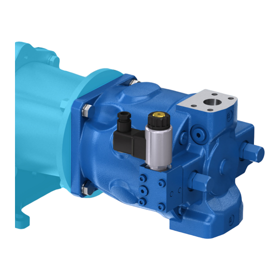
Page 18: Scope Of Delivery
18/72 A10FZO, A10VZO, A10FZG and A10VZG series 10 | Scope of delivery 4 Scope of delivery Abb� 1: Axial piston unit A10FZO Abb� 2: Axial piston unit A10VZO Abb� 3: Axial piston unit A10FZG Bosch Rexroth AG, RE 91485-01-B/2021-11-18... - Page 19 • Axial piston unit as per order confirmation The following parts come assembled on the unit: • Protective covers (1) • Protective plug/threaded plugs (2) • For version with through drive, protective cover incl. mounting bolts (3) • Transport protection for the through drive (4) RE 91485-01-B/2021-11-18, Bosch Rexroth AG...
-
Page 20: About This Product
In the closed circuit, the hydraulic fluid flows from the axial piston unit to the consumer, e.g. hydraulic cylinder, and from there directly back to the axial piston unit. There is a high-pressure side and a low-pressure side which alternate depending on which side is under load. Bosch Rexroth AG, RE 91485-01-B/2021-11-18... -
Page 21: Axial Piston Unit Layout
1 Drive shaft 7 Pre-compression 12 Piston 2 Retaining plate volume (optional) 13 Slipper pad 3 Opposed piston 8 Suction side 14 Cradle 4 Spring 9 Control valve 5 High-pressure side 10 Cylinder 6 Distributor plate 11 Stroking piston RE 91485-01-B/2021-11-18, Bosch Rexroth AG... -
Page 22: Functional Description
Torque and rotational speed are applied to the drive shaft by a drive motor. The drive shaft is connected to the cylinder by splines, causing the cylinder to rotate. With every revolution, the pistons perform a stroke in the cylinder bores, Bosch Rexroth AG, RE 91485-01-B/2021-11-18... - Page 23 Increasing the swivel angle increases the displacement; reducing the angle reduces displacement accordingly. Various control devices are available depending on requirements. Information about this can be found in data sheet 91485. RE 91485-01-B/2021-11-18, Bosch Rexroth AG...
-
Page 24: Product Identification
Direction of rotation, Direction of rotation Flow viewed on drive shaft and port assignment Type code Clockwise A to B designation "R" Counterclockwise B to A Type code Counterclockwise B to A designation "L" Clockwise A to B Bosch Rexroth AG, RE 91485-01-B/2021-11-18... -
Page 25: Flow Direction A10Vzo
S to B Clockwise B to S 5�6 Flow direction A10FZG and A10VZG Flow direction Tabelle 9: Direction of rotation, Direction of Flow viewed on drive shaft rotation Type code "W" Clockwise A to B Counterclockwise B to A RE 91485-01-B/2021-11-18, Bosch Rexroth AG... -
Page 26: Transport And Storage
Dimensions vary by equipment. The values applicable for your axial piston unit can be found in the installation drawing Height (request if necessary). Depth Weight may vary by equipment. Dimensions and weights Tabelle 13: Dimensions and weights A10VZG Size Weight 11.3 13.5 Bosch Rexroth AG, RE 91485-01-B/2021-11-18... -
Page 27: Transport By Hand
▶ Make sure that the eye bolt can bear the total weight of the axial piston unit plus 20%. You can lift the axial piston unit as shown in Abb. 10 with the eye bolt screwed into the drive shaft. RE 91485-01-B/2021-11-18, Bosch Rexroth AG... -
Page 28: Storing The Axial Piston Unit
• Storage areas should be free of corrosive materials and gases. • To prevent damage to the seals, do not operate ozone-forming equipment (e.g. mercury-vapor lamps, high-voltage equipment, electric motors, sources of electrical sparks or electrical discharge) in storage areas. Bosch Rexroth AG, RE 91485-01-B/2021-11-18... - Page 29 Once the max. storage time has elapsed, we recommend that you have the axial piston unit inspected by your Bosch Rexroth service partner. For questions regarding repair and spare parts, contact your proper Bosch Rexroth service partner or the service department of the manufacturer's plant of the axial piston unit, see chapter 10.5 "Spare parts"...
- Page 30 In such a case, consult your local contact person; you can find their contact information at https://addresses.boschrexroth.com Bosch Rexroth recommends the following procedure: 1� Clean the axial piston unit; see chapter 10.1 "Cleaning and care" on page 58. 2� Drain the axial piston unit.
-
Page 31: Installation
• Installation drawing for the axial piston unit (can be obtained from your contact person at Bosch Rexroth, if required) • Hydraulic circuit diagram for the axial piston unit (can be found in data sheet 91485 and on the installation drawing) •... - Page 32 91485 and in Tabelle 7 to Tabelle 9 "Flow direction" starting on page 24. ▶ Make sure that the working environment at the installation site is completely free of dust and foreign substances. The axial piston unit should be clean when Bosch Rexroth AG, RE 91485-01-B/2021-11-18...
-
Page 33: Installation Position A10Fzo, A10Vzo
2 and 3, the pump must be air bled and filled in a horizontal position prior to installation. NG3 … 18 t min t min t min A(B) A(B) A(B) NG21 … 63 t min t min t min A(B) A(B) A(B) Abb� 13: Below-reservoir installation A10FZO with installation position 1–3 RE 91485-01-B/2021-11-18, Bosch Rexroth AG... -
Page 34: Inside-Reservoir Installation
The axial piston unit is completely below the hydraulic fluid. If the minimum fluid level is equal to or below the upper edge of the pump, see chapter 7.3.3 "Above-reservoir installation" on page 36. Bosch Rexroth AG, RE 91485-01-B/2021-11-18... - Page 35 Please consult your proper contact person at Bosch Rexroth to commission an examination of the medium compatibility. Recommended installation position: 4. Because complete air bleeding and filling is not possible in installation positions 5, the pump must be air bled and filled in a horizontal position prior to...
-
Page 36: Above-Reservoir Installation
Above-reservoir installation means that the axial piston unit is installed above the minimum fluid level of the reservoir. Observe the maximum permissible suction height h = 800 mm. S max The permissible suction height h is derived from the total pressure loss. Bosch Rexroth AG, RE 91485-01-B/2021-11-18... - Page 37 Abb� 17: Above-reservoir installation A10FZO with installation position 6–8 Tabelle 19: Above-reservoir installation Installation position Air bleed Filling NG03 … 18 NG21 … 63 6 (drive shaft horizontal) 7 (drive shaft vertically up) 8 (drive shaft vertically down) RE 91485-01-B/2021-11-18, Bosch Rexroth AG...
-
Page 38: Installation Position A10Fzg, A10Vzg
Recommended installation position: 1. Because complete air bleeding and filling is not possible in installation positions 2 and 3, the axial piston unit must be air bled and filled in a horizontal position prior to installation. Bosch Rexroth AG, RE 91485-01-B/2021-11-18... - Page 39 A(B) t min A(B) A(B) Abb� 20: Below-reservoir installation A10VZG with installation position 1–3 Tabelle 22: Below-reservoir installation Installation position Air bleed Filling 1 (drive shaft horizontal) 2 (drive shaft vertically up) 3 (drive shaft vertically down) RE 91485-01-B/2021-11-18, Bosch Rexroth AG...
-
Page 40: Above-Reservoir Installation
Abb� 21: Above-reservoir installation A10FZG with installation position 4–6 Tabelle 23: Above-reservoir installation Installation position Air bleed Filling NG03 … 18 NG21 … 63 1 (drive shaft horizontal) 2 (drive shaft vertically up) 3 (drive shaft vertically down) Bosch Rexroth AG, RE 91485-01-B/2021-11-18... -
Page 41: Installing The Axial Piston Unit
4� Check the permissible direction of rotation of the axial piston unit (on the name plate) and make sure that this corresponds to the direction of rotation of the drive motor. RE 91485-01-B/2021-11-18, Bosch Rexroth AG... -
Page 42: Dimensions
The version of installation for the axial piston unit depends on the connecting elements to the drive side. The following descriptions explain the installation of the axial piston unit: • With a coupling 7�5�4 Installation with a coupling The following describes how to install the axial piston unit with a coupling: Bosch Rexroth AG, RE 91485-01-B/2021-11-18... -
Page 43: Remove The Spacer (For Version With Through Drive)
7�5�5 Remove the spacer (for version with through drive) Abb� 24: Removing the spacer Axial piston units with through drive are delivered with a spacer (1). The spacer is designed for transport protection and to reduce the hub's axial clearance (2). RE 91485-01-B/2021-11-18, Bosch Rexroth AG... -
Page 44: Completion Of Assembly
(3) is not pressure-resistant, it must be replaced with a pressure-resistant cover. If you need a pressure-resistant cover, contact your Bosch Rexroth Service partner. Use a suitable tool for this to prevent damage to the functional surfaces. If functional surfaces are damaged, contact your Bosch Rexroth service partner or the service department of the factory that... -
Page 45: Hydraulically Connecting The Axial Piston Unit
▶ Make sure that the corresponding suction and pressure port is assigned to the correct direction of rotation. Information on this can be found in data sheet 91485 and in Tabelle 7 to Tabelle 9 "Flow direction" starting on page 24. RE 91485-01-B/2021-11-18, Bosch Rexroth AG... - Page 46 (see chapter 7.3 "Installation position A10FZO, A10VZO" and "Installation position A10FZG, A10VZG" starting on page 33). • If the axial piston unit is equipped with installed screw fittings, do not remove them. Screw the stud end of the fitting directly into the installed fitting. Bosch Rexroth AG, RE 91485-01-B/2021-11-18...
- Page 47 ▶ Use the drawings (installation drawing) to determine the required stud end for each fitting. ▶ Make sure the right fittings, mounting bolts and threaded plugs are installed. ▶ For all female threads, use a stud end from the same system of units and of the correct size. RE 91485-01-B/2021-11-18, Bosch Rexroth AG...
- Page 48 Depending on the installation position, L or L must be connected (see chapter 7.3 "Installation position A10FZO, A10VZO" on page 33). Only for DG control. Only for port plate 22 and 32. Depending on the direction of rotation, please observe the information in this manual. Bosch Rexroth AG, RE 91485-01-B/2021-11-18...
- Page 49 O = Must be connected (plugged on delivery) X = Plugged (in normal operation) Dependent on the installation position, L, L or L must be connected (see chapter 7.3 "Installation position A10FZG, A10VZG" on page 38). RE 91485-01-B/2021-11-18, Bosch Rexroth AG...
- Page 50 These plugs must not be opened on the customer side! If you have opened the threaded plug accidentally, please contact your local contact person to ensure safe re-closing of the plug. You can find the address at https://addresses.boschrexroth.com Bosch Rexroth AG, RE 91485-01-B/2021-11-18...
- Page 51 The tightening torques for the threaded plugs are valid for the condition "dry" and "lightly oiled". The tightening torques for the threaded plugs are valid for the condition "dry" – in the condition "lightly oiled", the tightening torques for M10 × 1 are reduced to 10 Nm and for M12 × 1.5 to 17 Nm. RE 91485-01-B/2021-11-18, Bosch Rexroth AG...
-
Page 52: Electrically Connecting The Axial Piston Unit
• Correct pin assignment • Recommended electrical control units Exact details on the connector, type of protection and matching mating connector can also be found in data sheet 91485. The mating connector is not included in the scope of delivery. Bosch Rexroth AG, RE 91485-01-B/2021-11-18... -
Page 53: Performing Flushing Cycle
Abb� 31: HIRSCHMANN connector 7�6 Performing flushing cycle In order to remove foreign particles from the system, Bosch Rexroth recommends a flushing cycle for the hydraulic system before the first commissioning. To avoid internal contamination, do not include the axial piston unit in the flushing cycle. -
Page 54: Commissioning
Use only a hydraulic fluid that corresponds to the following requirements: Details regarding minimum requirements for hydraulic fluids can be found in Bosch Rexroth data sheet 90220. The titles of the data sheets can be found in Tabelle 1 "Required and supplementary documentation" on page 5. - Page 55 Commissioning | A10FZO/G, A10VZO/G 55/72 Bosch Rexroth evaluates hydraulic fluids on the basis of the Fluid Rating according to data sheet 90235. For hydraulic fluids which have been positively evaluated in the Fluid Rating, please refer to data sheet 90245 "Bosch Rexroth fluid rating list for Rexroth hydraulic components (pumps and motors)".
-
Page 56: Testing The Hydraulic Fluid Supply
▶ After starting the drive motor, check in particular the specified pressures, e.g. working pressure and case pressure. ▶ Perform a leak test without and with load prior to normal operation. ▶ If necessary, remove the pressure gauge and plug the ports with the specified threaded plugs. Bosch Rexroth AG, RE 91485-01-B/2021-11-18... -
Page 57: Running-In Phase
10 operating hours is concluded. To ensure that contamination in the hydraulic system does not damage the axial piston unit, Bosch Rexroth recommends the following procedure after the running-in phase: ▶ After the running-in phase, have a hydraulic fluid sample analyzed for the required cleanliness level. -
Page 58: Operation
10�2 Inspection In order for the axial piston unit to be reliable and long-lasting, Bosch Rexroth recommends inspecting the hydraulic system and axial piston unit on a regular basis, and documenting and archiving the following operating conditions:... -
Page 59: Maintenance
10�4 Repair Bosch Rexroth offers a comprehensive range of services for the repair of Rexroth axial piston units. Repairs on the axial piston unit and its assembled parts should only be performed by service centers certified by Bosch Rexroth. -
Page 60: Spare Parts
Address all questions regarding spare parts to your proper Bosch Rexroth Service partner or the service department of the manufacturer's plant of the axial piston unit. -
Page 61: Removal And Replacement
6� Remove the axial piston unit. Use a suitable lifting device. 7� Completely drain the axial piston unit. 8� Plug all openings. 11�4 Preparing the components for storage or further use ▶ Proceed as described in chapter 6.2 "Storing the axial piston unit" on page RE 91485-01-B/2021-11-18, Bosch Rexroth AG... -
Page 62: Disposal
Also observe the applicable safety data sheet for the hydraulic fluid. 4� Disassemble the axial piston unit into its constituent parts for proper recycling. 5� For example, separate the parts into: – Castings – Steel – Aluminum – Non-ferrous metal – Electronic waste – Plastic – Seals Bosch Rexroth AG, RE 91485-01-B/2021-11-18... -
Page 63: Extension And Conversion
Changes to settings on the customer side should only be made using the product-specific setting instructions. The warranty from Bosch Rexroth only applies to the configuration as delivered. The warranty will be voided if the unit is modified or extended. Adjusting the setting screws will render the warranty void. If you need to change the settings, please contact your local contact person;... -
Page 64: Troubleshooting
▶ Try to get a clear idea of the cause of the fault. Directly ask the (machine) operator. ▶ Document the work carried out. ▶ If the fault cannot be corrected, please refer to one of the contract addresses https://addresses.boschrexroth.com. Bosch Rexroth AG, RE 91485-01-B/2021-11-18... -
Page 65: Malfunction Table
Optimize the adjustment of the controller of the axial piston unit and the pressure limitation in the hydraulic system Mechanical damage to the axial piston unit Replace axial piston unit (e.g. bearing damage) Contact Bosch Rexroth Service Increased, unusual vibration Bearings worn Contact Bosch Rexroth Service RE 91485-01-B/2021-11-18, Bosch Rexroth AG... - Page 66 Malfunction of the control device or controller Contact Bosch Rexroth Service of the axial piston unit Control of the control device defective Check control (contact machine/system manufacturer or Bosch Rexroth Service) Wear or mechanical damage to the Replace axial piston unit axial piston unit Contact Bosch Rexroth Service...
- Page 67 Malfunction of the control device or controller Contact Bosch Rexroth Service of the axial piston unit Control of the control device defective Check control (contact machine/system manufacturer or Bosch Rexroth Service) Wear or mechanical damage to the Replace axial piston unit axial piston unit Contact Bosch Rexroth Service Output unit defective (e.g. hydraulic motor...
- Page 68 Unstable control signal Contact machine/system manufacturer or Bosch Rexroth Service Malfunction in the control devices or the Contact Bosch Rexroth Service controller Excessively high temperature of Excessively high inlet temperature at the Machine/system manufacturer: Inspect system, hydraulic fluid and housing axial piston unit e.g. malfunction in the cooler, insufficient...
-
Page 69: Technical Data
The permissible technical data for your axial piston unit can be found on the data sheet 91485. Data sheet 91485 can be found in the Bosch Rexroth media directory at www.boschrexroth.com/mediadirectory Additional information can be found in the online product catalog at www.boschrexroth.com/p-A10FZO-1x... -
Page 70: Alphabetical Index
Filling ........... 54 Performance description ....20 Flushing cycle ....... 53 Piston ........21, 22 Functional description Port overview ......48, 49 Control ........23 Port plate ....... 21, 22 Functional test ......56 Pre-compression volume ....21 Bosch Rexroth AG, RE 91485-01-B/2021-11-18... - Page 71 Technical data ......69 Tightening torques ......50 Tools ..........61 Transport ........26 By hand ........27 with eye bolt ......27 with lifting strap ......28 Transporting ......... 26 Transport protection ....44, 45 Troubleshooting ......64 RE 91485-01-B/2021-11-18, Bosch Rexroth AG...
- Page 72 Bosch Rexroth AG An den Kelterwiesen 14 72160 Horb a.N. Germany Tel. +49 7451 92-0 info.ma@boschrexroth.de www.boschrexroth.com Your local contact person can be found at: www.boschrexroth.com/addresses Subject to change RE 91485-01-B/2021-11-18...