
Related Manuals for Raymarine YACHTSENSE DCS


Summary of Contents for Raymarine YACHTSENSE DCS
- Page 1 YACHTSENSE Installation and operation instructions English (en-US) Date: 04-2021 Document number: 81394-2 © 2021 Raymarine UK Limited...
- Page 3 Please check the website to ensure you have the latest documentation. Publication copyright Copyright ©2021 Raymarine UK Ltd. All rights reserved. No parts of this material may be copied, translated, or transmitted (in any medium) without the prior written permission of Raymarine UK Ltd.
-
Page 5: Table Of Contents
Contents Chapter 1 Important information..................9 Water ingress ..........................9 Disclaimer ........................... 9 Open source license agreements ..................10 Declaration of Conformity......................10 Warranty registration ........................ 10 Product disposal ........................10 IMO and SOLAS ........................10 Technical accuracy ........................11 Chapter 2 Document and product information............ - Page 6 4.2 Module to module connections..................32 4.3 Molex connectors......................32 Molex connector types and keying..................33 Removing connectors from modules ..................33 Removing seal plugs......................34 Inserting seal plugs.......................34 Wiring Molex connectors ......................35 Connecting Molex connectors to modules ................36 4.4 Master module connections..................... 37 Master module pin out......................
- Page 7 7.1 Service and maintenance....................78 Routine equipment checks ....................78 7.2 Product cleaning........................ 78 Chapter 8 Technical support ..................79 8.1 Raymarine product support and servicing ..............80 8.2 Learning resources ......................81 Chapter 9 Technical specification................. 83 9.1 System technical specification ..................84 System power specification ....................84...
- Page 8 10.4 SeaTalkng ® cables and accessories ................92 Appendix A NMEA 2000 PGN support ................ 95...
-
Page 9: Chapter 1 Important Information
Raymarine. Raymarine is not responsible for damages or injuries caused by your use or inability to use the product, by the interaction of the product with products manufactured by others, or by errors in information utilized by the product supplied by third parties. -
Page 10: Open Source License Agreements
For more information about suitable collection points for waste electrical and electronic equipment in your region, refer to the Raymarine website: www.raymarine.eu/recycling. IMO and SOLAS... -
Page 11: Technical Accuracy
In addition, our policy of continuous product improvement may change specifications without notice. As a result, Raymarine cannot accept liability for any differences between the product and this document. Please check the Raymarine website (www.raymarine.com) to ensure you have the most up-to-date version(s) of the documentation for your product. -
Page 13: Chapter 2 Document And Product Information
Chapter 2: Document and product information Chapter contents • 2.1 Product documentation on page 14 • 2.2 Product overview on page 15 Document and product information... -
Page 14: Product Documentation
2.1 Product documentation The following documentation is applicable to your product: This and other Raymarine product documents are available to download in PDF format from www.raymarine.com/manuals. • 81394 — YachtSense Digital Control System Installation and Operation Instructions (this document) • 87407 — YachtSense Digital Control System Mounting Template •... -
Page 15: Product Overview
• Control of digital and analog output signals (up to 250 mA). • Monitoring of digital and analog input signals • Remote control via networked Raymarine Multifunction Displays (MFDs) using customized pages. • Dedicated LCD screen and button controls included on master and Remote modules for manual override, device diagnostics and channel status. -
Page 16: Configuration Required
Maximum current (100% duty cycle) Important: • To protect your vessel and connected equipment, modules will shut down if their internal temperature exceeds 85°C. • If your system will exceed these limits please consult Raymarine technical support for assistance. -
Page 17: Applicable Products
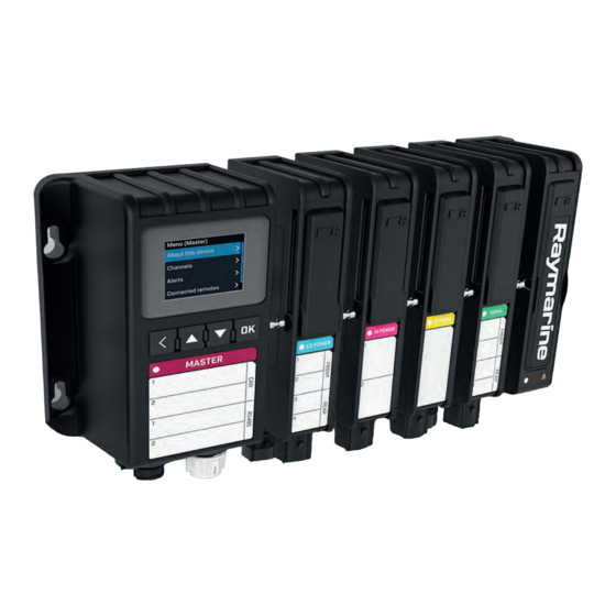
Applicable products The following YachtSense ™ Digital Control System modules are available: Master module (E70592) • The Master module is required for all installation scenarios and is supplied with a Power supply module (E70604). • The Master module can be controlled using a networked Multifunction display (MFD) •... -
Page 18: System Hardware Configuration
• The Power supply module is connected on the end of the Master system assembly or Remote system assembly. • The Power supply module connects to the vessel’s power supply and provides power to the system. System hardware configuration As a minimum the YachtSense ™ Digital Control System must consist of a Master system that includes a Master module and a Power supply module. -
Page 19: Required Additional Items
Required additional items The following additional items are required when installing a YachtSense Digital Control System. Fixings appropriate for mounting surface and 5 mm (0.2 in) module mounting holes (4 x fixings are required assemblies with less than 4 input / output modules. 7 x fixings are required for assemblies with 4 or more input / output modules.) 2. -
Page 21: Chapter 3 Installation
Chapter 3: Installation Chapter contents • 3.1 Tools required on page 22 • 3.2 Selecting a location on page 22 • 3.3 Master system and Remote system dimensions on page 24 • 3.4 Camlock system on page 25 • 3.5 Assembling Master or Remote systems on page 25 •... -
Page 22: Tools Required
Chapter 1 Important information section of this document. EMC installation guidelines Raymarine equipment and accessories conform to the appropriate Electromagnetic Compatibility (EMC) regulations, to minimize electromagnetic interference between equipment and minimize the effect such interference could have on the performance of your system... -
Page 23: Location Requirements
For optimum EMC performance we recommend that wherever possible: • Raymarine equipment and cables connected to it are: – At least 1 m (3.3 ft) from any equipment transmitting or cables carrying radio signals e.g. VHF radios, cables and antennas. -
Page 24: Master System And Remote System Dimensions
3.3 Master system and Remote system dimensions Product dimensions for the system are provided below. A = 81.00 mm (3.19 in) B = 28.00 mm (1.10 in) per module — minimum = 0 and maximum = 6 (168 mm / 6.61 in) C = 86.50 mm (3.40 in) Minimum D = 5.87 mm (0.23 in) E = 27.50 mm (1.08 in) -
Page 25: Camlock System
3.4 Camlock system Input and output modules and power supply modules include a camlock system that is used to lock the modules together. The camlock system consists of 3 camlocks on each module, one on the front and 2 on the rear. The modules are supplied with the camlocks in the unlocked position. Locking the modules Lock the modules in position one at a time. - Page 26 2. Ensure that the camlocks on the front and back of the Input and Output modules and the Power supply module are in the unlocked position. 3. Connect the Input and Output modules to the Master or Remote module in configuration order. i.
-
Page 27: Mounting Options
3.6 Mounting options Depending on module configuration Master and Remote systems can be mounted with or without the included mounting bracket. When a Master system or Remote system includes 4 or more input / output modules extra mounting support is required. The supplied mounting bracket and rear shim should be used. 3.7 Mounting using the bracket Fitting the mounting bracket Master systems and Remote systems are supplied with a mounting bracket and rear shim. -
Page 28: Mounting Systems Using The Bracket
Mounting systems using the bracket Follow the steps below to mount Master system assembly and Remote system assemblies that include 4 or more input / output modules.. Important: • To help prevent water ingress, systems must be mounted vertically with the connectors facing down. -
Page 29: Mounting Without The Bracket
3.8 Mounting without the bracket Follow the steps below to mount Master system assembly and Remote system assemblies. Important: • To help prevent water ingress, systems must be mounted vertically with the connectors facing down. • Use 4 x fixings, not supplied, appropriate for the intended mounting surface. The fixings should be appropriate width for the 5 mm (0.2 in) module mounting holes. -
Page 30: Mounting Using The Mounting Template
3.9 Mounting using the mounting template A mounting template is provided which can aid installation in confined or difficult to reach places. Important: • To help prevent water ingress, systems must be mounted vertically with the connectors facing down. • Use 4 x fixings, not supplied, appropriate for the intended mounting surface. The fixings should be appropriate width for the 5 mm (0.2 in) module mounting holes. -
Page 31: Chapter 4 Connections
Chapter 4: Connections Chapter contents • 4.1 General cabling guidance on page 32 • 4.2 Module to module connections on page 32 • 4.3 Molex connectors on page 32 • 4.4 Master module connections on page 37 • 4.5 Remote module connections on page 38 •... -
Page 32: General Cabling Guidance
• Unless otherwise stated only use cables supplied by Raymarine. • Where it is necessary to use non-Raymarine cables, ensure that they are of correct quality and gauge for their intended purpose. (e.g.: longer power cable runs may require larger wire gauges to minimize voltage drop along the run). -
Page 33: Molex Connector Types And Keying
Molex connector types and keying The types of connectors used and their keying is shown below Master module 16–pin connector (Molex : 33472–1601) 2. Remote module 20–pin connector (Molex : 33472–2001) 3. Signal module 4–pin connector (Molex : 33472–4002) 4. Output module 4 —pin connector (Molex : 33472–4001) Note: The connectors used for the Signal module and Output modules are keyed differently. -
Page 34: Removing Seal Plugs
Removing seal plugs The Molex connector supplied with the Master module is supplied with seal plugs fitted to each of its 16 terminals. To wire the connector the relevant seal plugs will need to be removed. Follow the steps below to remove seal plugs from the Molex connectors. 1. -
Page 35: Wiring Molex Connectors
1. If required, insert a small flat blade screwdriver into the pry point and using the connector housing as a pivot point, pry out the connector insert, known as the TPA (Terminal Position Assurance), until it reaches the pre-lock position. 2. -
Page 36: Connecting Molex Connectors To Modules
5. Place the wire in a female receptacle crimp so that the exposed copper is level with the end of the conductor crimp and the insulation protrudes slightly form the end of the insulation crimp. A — Female crimp connector B —... -
Page 37: Master Module Connections
4.4 Master module connections The Master module is the primary control module of the YachtSense ™ Digital Control System The Master module controls all input and output modules connected to it and all Remote systems. It acts as the interface between the system and Multifunction display (MFD) and peripheral remote controllers. -
Page 38: Remote Module Connections
Master module signal / pin Vessel connection signal / pin CAN2 Low CAN2 / J1939 L RS-485 2 Negative RS-485 Data2 - RS-485 2 ground RS-485 Data2 GRD (0 V) RS-485 1 Negative RS-485 Data1 - Not connected Not applicable Do not connect Not applicable 4.5 Remote module connections... -
Page 39: Remote Pin Out
Remote pin out The 20 pin connector on the Remote module allows connection of up to 8 digital / analog input and up to 200 mA output channels, commonly used to control switches, sensors, relays and actuators. The module’s connector pin out is shown below. IO CH1 + CH1 - IO CH2 +... - Page 40 Example — Resistive sensor (Analog input ) Example — 2 wire 4–20 mA sensors Example — 3-wire 4–20 mA sensors...
-
Page 41: Hi Power Module Connections
Example — 4 wire 4–20 mA sensors 4.6 Hi power module connections The Hi power module is a digital output module and can be used to drive high powered electrical loads such as pumps, fans, heaters, refrigerators and Hi-Fi equipment etc. Channel capabilities: •... -
Page 42: Inductive Loads
CH1+ CH2+ CH1- CH2- Important: • The negative power cable (0 V return) of the system must be connected to the same battery negative as all input and output devices that are being controlled or monitored by that system. • Each load must have both a supply and return connection to the module. Example —... -
Page 43: Lo Power Module Connections
Important: When connecting the diode ensure that: • The diode is placed directly across the load • The wire length is kept to an absolute minimum. • The wire gauge is the same as the wire gauge used for the load. Diode requirements: •... - Page 44 Front connector CH1+ CH2+ CH1– CH2– Rear connector CH3+ CH4+ CH3– CH4– Important: • The negative power cable (0 V return) of the system must be connected to the same battery negative as all input and output devices that are being controlled or monitored by that system. •...
-
Page 45: Inductive Loads
Example — Wiper motor connection P — Park position I — Intermittent speed S — Slow speed F — Fast speed G — Ground Inductive loads Whilst inductive loads such as motors, relays and solenoids etc. are energized they store energy, when switched off the stored energy must be safely discharged. -
Page 46: Reverse Power Module Connections
4.8 Reverse power module connections The Reverse power module is a digital output module, and can be used to drive devices such as hydraulic pumps or actuators which require the motor to drive forwards and in reverse. Channel capabilities: • 20 A reversible drive module •... -
Page 47: Reversible Motor Inductive Loads
Reversible motor inductive loads Whilst reversible motors are energized they store energy, when switched off the stored energy must be safely discharged. Unless the connected load specifically states that it includes internal flyback/freewheel diodes then external diodes must be fitted. Note: Failure to fit the diodes will result in permanent damage to the module. -
Page 48: Digital And Analog Inputs And Outputs Example Connections
Front connector CH1+ (signal) CH2+ (signal) CH1- (return) CH2- (return) Rear connector CH3+ (signal) CH4+ (signal) CH3- (return) CH4- (return) Digital and analog inputs and outputs example connections The Remote module and Signal module can be used to control and or monitor digital and analog inputs / outputs such as switches, resistive sensors, pressure sensors secondary batteries etc. - Page 49 Example — Resistive sensor (Analog input ) Example — 2 wire 4–20 mA sensors Example — 3-wire 4–20 mA sensors Connections...
-
Page 50: Connecting The Power Supply
Example — 4 wire 4–20 mA sensors 4.10 Connecting the power supply The Power supply module is supplied with the Master modules and with Remote modules and provides power to the system and connected devices. • An appropriate rated 2 core power cable is required. 1. -
Page 51: Thermal Breaker / Inline Fuse Rating
2. Open the door on the side of the Power supply module by pulling the tab forwards whilst opening the door. 3. Remove the protective covers from the power connection studs, leaving them attached to the Power supply module. Important: The protective covers are attached to the Power supply module by lanyards, do not disconnected the protective covers form the Power supply module. -
Page 52: Power Cable Requirements
Each output channel should be fused with a fuse rated appropriately for the current draw of that channel. Important: Each output module is supplied with the maximum rated fuse for the channel (e.g.: The Dual Power supply module is supplied with a 20 A fuse fitted to each channel). Ensure that if required, the fuses are changed to reflect the actual current draw of the devices connected to each channel. - Page 53 Implementation — connection to distribution panel Power supply negative (-) Black wire 2. Power supply positive (+) Red wire 3. Waterproof thermal circuit breaker or inline fuse (rating determined by system current draw). • It is recommended that the supplied power cable is connected to a suitable breaker or switch on the vessel's distribution panel or factory-fitted power distribution point.
-
Page 54: Replacing Module Fuses
4.11 Replacing module fuses Output modules are supplied with micro blade fuses fitted to each channel. The fuses are maximum rated for the channel’s maximum load capacity. Note: It is important that the fitted fuse rating reflects the load of the channel. Where the actual channel load is less than the maximum load capacity the fuse should be replaced by an appropriately rated fuse. -
Page 55: Fuse Labeling
Fuse labeling During installation the fuses for each module in the system must be checked to ensure that the fuses are appropriately rated for each channel’s current draw. Ensure that if required, the fuses are changed to reflect the actual current draw of the devices connected to each channel. It is also important to make a note of the ratings of the fitted fuses, using the label provided on the front of each module. -
Page 56: Fuse By-Pass
Important: When replacing fuses ensure that the replacement fuse is rated the same as the fuse being replaced. 4.12 Fuse by-pass If a Hi power module channel or Lo power module channel fails and all efforts to restore have been unsuccessful then the module channel can be temporarily by-passed. -
Page 57: Connecting Seatalkng ® Cables
Example — Dedicated SeaTalkng ® system Note: For simplicity, the example above shows a SeaTalkng network dedicated to YachtSense Digital Control System, however other SeaTalkng devices can be connected. Note: The illustration above shows only the dedicated power supply for the SeaTalkng network. Additionally, the MFD and the YachtSense Digital Control System Master module each require their own power supplies. -
Page 58: Seatalkng Power Supply
3. Fully insert the cable connector.. 4. Rotate the locking collar clockwise (2 clicks) until it is in the locked position. SeaTalkng power supply A SeaTalkng ® backbone requires a single 12 V dc power supply. Power can be supplied to the SeaTalkng ®... -
Page 59: In-Line Fuse And Thermal Breaker Ratings
In the example above the backbone has an overall LEN of 10, so the optimum connection point would be to have 5 LEN either side of the connection point. Small systems If the backbone length is 60 m (197 ft) or less, the power connection point may be connected at any point in the backbone. -
Page 60: Power Distribution - Seatalkng
• The information provided below is for guidance only, to help protect your product. It covers common vessel power arrangements, but does NOT cover every scenario. If you are unsure how to provide the correct level of protection, please consult an authorized Raymarine dealer or a suitably qualified professional marine electrician. - Page 61 Waterproof fuse holder with 5 A inline fuse must be fitted (not supplied). 2. SeaTalkng ® power cable. 3. RF Ground connection point for drain wire. • Ideally, the SeaTalkng ® power cable should be connected to a suitable breaker or switch on the vessel's distribution panel or factory-fitted power distribution point.
- Page 62 Waterproof fuse holder with 5 A inline fuse must be fitted (not supplied). 2. SeaTalkng ® power cable. 3. Drain wire connection point. Battery connection scenario A: Suitable for a vessel with a common RF ground point. In this scenario, the power cable’s drain wire should be connected to the vessel’s common RF ground point.
-
Page 63: Raynet Network Connection
• ABYC A-31 Battery chargers and Inverters • ABYC TE-4 Lightning Protection 4.14 RayNet network connection The Master module communicates with Raymarine Axiom™ series MFDs using the SeaTalkhs ® network. Note: • The example below uses a network switch, however the Master module can also be connected directly to an MFD’s RayNet network connection. -
Page 65: Chapter 5 Operations
Chapter 5: Operations Chapter contents • 5.1 Controls on page 66 • 5.2 Default page on page 66 • 5.3 Menu on page 67 • 5.4 Channels pages on page 67 • 5.5 Alerts on page 70 Operations... -
Page 66: Controls
5.1 Controls Master and Remote modules have the following control buttons: Back — Select to go back to the previous screen. 2. OK — Open menus or confirm menu selection or value adjustment. 3. Up — Move up through lists or channel pages. 4. -
Page 67: Menu
5.3 Menu System information, channel status and alert information and related settings can be accessed from the menu. The menu is accessed by pressing the OK button from the default screen. The following options are available from the Master / Remote module menu:. •... -
Page 68: Options Menu
Example input and output channel pages Input channel pages provide the following information relevant to the channel being viewed: • Module number • Channel number • Channel name • Channel voltage 2. Output channel pages provide the following information relevant to the channel being viewed: •... -
Page 69: Manual Override
Each output channel is configured with a soft fuse rating. Note: • Do NOT change fuse rating level without first consulting a Raymarine certified engineer. • Soft fuse ratings are configured during installation and should not require adjustment. If soft fuses are tripping then this suggests an issue with the connected device. -
Page 70: Alerts
The tripped fuse can be reset by pressing the OK button. Important: If fuse tripping persists, consult a Raymarine certified engineer to help fix the problem. as this suggests an issue with a connected device. 5.5 Alerts When an alert occurs a notification is displayed on the default page of the Master or Remote module that is directly connected to the module(s) that has channel(s) with active alerts. -
Page 71: Limp Home Mode
2. Alert details page Cycle through the active alerts using the Up and Down buttons. Pressing the OK button will display the details page for the highlighted alert. Pressing the OK button on the alert details page will action the stated option, e.g.: Reset, Exit override etc. -
Page 73: Chapter 6 Troubleshooting
Chapter 6: Troubleshooting Chapter contents • 6.1 Troubleshooting on page 74 • 6.2 LED diagnostics on page 74 • 6.3 YachtSense Digital Control System troubleshooting on page 74 • 6.4 Performing a factory reset on page 75 • 6.5 Deleting configuration on page 75 Troubleshooting... -
Page 74: Troubleshooting
If after referring to this section you are still having problems with your product, please refer to the Technical support section of this manual for useful links and Raymarine Product Support contact details. -
Page 75: Performing A Factory Reset
• This procedure should only be carried out by Raymarine certified engineers. • This procedure cannot be undone. • The system will require re-configuration by a Raymarine approved dealer before it can be used again. 1. Select About this device from the menu. -
Page 77: Chapter 7 Maintenance
Chapter 7: Maintenance Chapter contents • 7.1 Service and maintenance on page 78 • 7.2 Product cleaning on page 78 Maintenance... -
Page 78: Service And Maintenance
7.1 Service and maintenance This product contains no user serviceable components. Please refer all maintenance and repair to authorized Raymarine dealers. Unauthorized repair may affect your warranty. Warning: High voltage This product contains high voltage. Adjustments require specialized service procedures and tools only available to qualified service technicians. There are no user serviceable parts or adjustments. -
Page 79: Chapter 8 Technical Support
Chapter 8: Technical support Chapter contents • 8.1 Raymarine product support and servicing on page 80 • 8.2 Learning resources on page 81 Technical support... -
Page 80: Raymarine Product Support And Servicing
You can obtain this product information using diagnostic pages of the connected MFD. Servicing and warranty Raymarine offers dedicated service departments for warranty, service, and repairs. Don’t forget to visit the Raymarine website to register your product for extended warranty benefits: http://www.raymarine.co.uk/display/?id=788. United Kingdom (UK), EMEA, and Asia Pacific: •... -
Page 81: Learning Resources
Russia (Authorized Raymarine distributor): • E-Mail: info@mikstmarine.ru • Tel: +7 495 788 0508 8.2 Learning resources Raymarine has produced a range of learning resources to help you get the most out of your products. Video tutorials Raymarine official channel on YouTube: • YouTube LightHouse™... -
Page 83: Chapter 9 Technical Specification
Chapter 9: Technical specification Chapter contents • 9.1 System technical specification on page 84 • 9.2 Master module technical specification on page 84 • 9.3 Remote module technical specification on page 85 • 9.4 Power supply module technical specification on page 85 •... -
Page 84: System Technical Specification
9.1 System technical specification System power specification Nominal supply voltage: 12 V dc / 24 V dc Operating voltage range: 8 V dc to 32 V dc Maximum output current: 100 A per Master system / Remote system Environmental specification Operating temperature range: -25°C (-13°F) to 55°C (131°F) Storage temperature range:... -
Page 85: Remote Module Technical Specification
9.3 Remote module technical specification Power specification Nominal supply voltage: 12 V dc / 24 V dc Operating voltage range: 8 V dc to 32 V dc Module current draw: 250 mA Maximum output current: 2 A (250 mA per channel) Data connections SeaTalkng ®... -
Page 86: Hi Power Module Technical Specification
9.5 Hi power module technical specification Power specification Nominal supply voltage: 12 V dc / 24 V dc Operating voltage range: 8 V dc to 32 V dc Maximum output current: 40 A (20 A per channel) Minimum output current: 50 mA per channel Data connections Hi power connections:... -
Page 87: Reverse Power Module Technical Specification
Physical data Module Dimensions: H/W/D (not including 172 mm (6.77 in) x 28.00 mm (1.10 in) x 76.50 mm busbars): (3.01 in) Weight: 0.22 Kg (0.49 lb) 9.8 Reverse power module technical specification Power specification Nominal supply voltage: 12 V dc / 24 V dc Operating voltage range: 8 V dc to 32 V dc Maximum output current:... -
Page 89: Chapter 10 Spares And Accessories
Chapter 10: Spares and accessories Chapter contents • 10.1 YachtSense Digital Control System spares on page 90 • 10.2 YachtSense Digital Control System accessories on page 90 • 10.3 RayNet to RayNet cables and connectors on page 91 • 10.4 SeaTalkng ® cables and accessories on page 92 Spares and accessories... -
Page 90: Yachtsense Digital Control System Spares
10.1 YachtSense Digital Control System spares • Replacement Master module — R70805 • Replacement Power supply module — E70604 • Replacement Remote module — R70806 10.2 YachtSense Digital Control System accessories • Pack of 50 MX150L Seal plugs (34345–0001) — A80624 •... -
Page 91: Raynet To Raynet Cables And Connectors
10.3 RayNet to RayNet cables and connectors Standard RayNet connection cable with a RayNet (female) socket on both ends. 2. Right-angle RayNet connection cable with a straight RayNet (female) socket on one end, and a right-angle RayNet (female) socket on the other end. Suitable for connecting at 90° (right angle) to a device, for installations where space is limited. -
Page 92: Seatalkng ® Cables And Accessories
10.4 SeaTalkng ® cables and accessories SeaTalkng ® cables and accessories for use with compatible products. SeaTalkng kits SeaTalkng kits enable you to create a simple SeaTalkng backbone. • Starter kit — T70134 – 1 x 5 Way connector (A06064) –... - Page 93 • 5–way connector block (3 x spur connections) — A06064 • Backbone extender — A06030 • Spur blanking plug — A06032 • Inline terminator — A80001 — Provides direct connection of a spur cable to the end of a backbone cable.
- Page 95 Appendix A NMEA 2000 PGN support Administration PGNs • 59392 — ISO Acknowledge (Receive / Transmit) • 59904 — ISO Request (Receive / Transmit) • 60160 — ISO Transport protocol, data transfer (Receive) • 60416 — ISO Transport protocol, connection management — BAM group function (Receive) •...
- Page 97 Index SeaTalkng power..........58 SeaTalkng power cable ........60 Connections Output Hi power ..............42 Accessories ............90 ConnectionsOutput DeviceNet adaptor cables ........93 Lo power.............. 44 DeviceNet power cables ........93 Contact details............80 Network cables............ 91 Control buttons............66 RayNet cables............91 SeaTalkng adaptor cables ........93 SeaTalkng backbone cables .......92 SeaTalkng backbone connectors ......92 Declaration of Conformity........
- Page 98 Location requirements General ..............23 RayNet cables ..............91 RayNet network............37 Remote module ..........17–18, 38 Maintenance............9, 78 Pin out..............39 Manual override ............68 Remote system........... 14, 18 Master module..........17–18, 37 Reverse power module ........17, 46 Pin out..............37 Routine checks ............
- Page 99 Water ingress ............23 Water ingress protection .........84 WEEE Directive............10 YachtSense Digital Control System......14...
- Page 102 Raymarine Marine House, Cartwright Drive, Fareham, Hampshire. PO15 5RJ. United Kingdom. Tel: +44 (0)1329 246 700 www.raymarine.com a brand by...