Table of Contents
Advertisement
Quick Links
Advertisement
Chapters
Table of Contents

Summary of Contents for Narco Avionics NAV122D
- Page 1 NARCO AVIONICS NAV122D, NAV122D/GPS TSO’d NAVIGATION SYSTEM Installation Manual 03128-0620 NARCO AVIONICS INC. 270 COMMERCE DR , STE 200., FORT WASHINGTON PA 19034 (215)-643-2900 FAX (215)-643-0197 www.narcoavionics.com COPYRIGHT, NARCO AVIONICS INC., 2007 PRINTED IN USA MARCH 2007 Rev 1.2...
-
Page 3: Table Of Contents
TABLE OF CONTENTS SECTION TOPIC PAGE NUMBER NUMBER INTRODUCTION GENERAL 1.1.1 Manual Organization PRODUCT DESCRIPTION DESIGN FEATURES PRODUCT SPECIFICATIONS UNITS AND ACCESSORIES SUPPLIED OPTIONAL ACCESSORIES 1.6.1 Miscellaneous Items NOT Supplied OPERATOR LICENSE REQUIREMENT OPERATION LIST OF TABLES TABLE TITLE PAGE NUMBER NUMBER NAV SYSTEM CHARACTERISTICS... - Page 4 THIS PAGE INTENTIONALLY LEFT BLANK...
-
Page 5: Introduction
SECTION 1 1. INTRODUCTION 1.1 GENERAL In support of the NARCO Avionics NAV122D, NAV122D/GPS navigation systems, this manual provides detailed installation procedures. “This manual is intended for use only by persons who are qualified to service the equipment described in this manual pursuant to current regulatory requirements.”... -
Page 6: Design Features
ARINC Panel cutout, 3” instrument hole. Direct replacement of existing NAV122 (minus marker RCVR) Easily replaces NAV111/NAV112 receivers (cable modification required) The NAV122D/GPS can be used as the external CDI display required in a IFR certified GPS installation Meets the following TSO’s: C-40c... -
Page 7: Vor/Loc Receiver
INTRODUCTION SECTION 1 1.4 Continued TABLE 1.3 VOR/LOC RECEIVER VOR/LOC RECEIVER NAV122D Frequency Range (in MHz) 108.00 to 117.95 200 channels Sensitivity (6dB S + N/N) 2.0µV (Full VOR Flag) 2.0µV Spurious and Image Rejection 80dB min ±19kHz Selectivity ±42kHz 60dB 1.0dB max... -
Page 8: External Indicator And Autopilot Loads
150mV full scale GS FLAG 1000 OHMS 250mV full scale ENVIRONMENTAL The NAV122D and NAV122D/GPS are designed and tested to meet the appropriate categories of RTCA DO-160C. The environmental qualification form can be found in appendix A Operating temperature -20°C to +55°C... -
Page 9: Units And Accessories Supplied
SECTION 1 1.4.1 Explanation The NAV122D and NAV122D/GPS are designed to be instrument panel mounted within the cabin environment of fixed and rotary wing aircraft using piston or turbine engines, in single and multiengine configurations. It is designed for non-pressurized aircraft operating up to 35,000 feet as well as for pressurized aircraft. -
Page 10: Optional Accessories
NARCO AVIONICS NAV122D, NAV122D/GPS TABLE 1.8 INSTALLATION KIT PARTS LIST PART QUANTITY ITEM DESCRIPTION NUMBER 03128 0500 0501 0502 41364-0008 Connector, J810, 37 Pin 41307-0008 Hood, J810, Right Angle 41308-0004 Locking Assembly, J810 41152-0003 Connector, BNC 41372-0004 Contacts, Socket, Qty. 37... -
Page 11: Operation
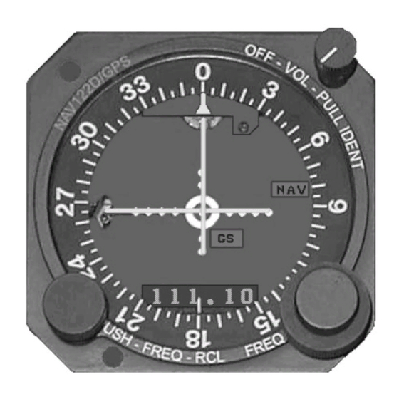
INTRODUCTION SECTION 1 1.8 OPERATION Rotating the Volume Control/Ident clockwise, past the “click”, applies power to the NAV circuits; continued clockwise rotation increases audio volume. Pulling this knob allows the 1020Hz Ident code to be heard. Receive Frequency Channeling Receive frequency is selected by the concentric knobs at the Units lower right corner. Whole megahertz frequencies are selected by the large knob while fractional megahertz frequencies are selected by the small knob. - Page 12 GS Flag - Red GS Flag alerts the pilot to either loss of signal or inadequate signal level. NAV122D/GPS ADDITIONAL FUNCTIONS When the NAV122D/GPS is being used as the CDI for an IFR certified GPS and the appropriate GPS mode pin on P811 is active (frequency display now showing ‘GPS’), the following operations apply: Frequency Recall Pressing on the OBS knob will momentarily display the current NAV frequency.
-
Page 13: Table Of Contents
TABLE OF CONTENTS SECTION TOPIC PAGE NUMBER NUMBER INTRODUCTION PRELIMINARY PROCEDURES 2.2.1 Preliminary inspection 2.2.2 Pre Installation Bench Test 2.2.2.1 Test Equipment Required 2.2.2.2 Bench Test Wiring Harness 2.2.2.3 Test Procedure MECHANICAL INSTALLATION ELECTRICAL INSTALLATION 2-10 2.4.1 Antenna Connections 2-13 2.4.2 Interconnect Cable (P810) 2-13... - Page 14 NAV122D/GPS CONNECTIONS (Chas. BACBCED and later) 2-21 LIST OF TABLES TABLE TITLE PAGE NUMBER NUMBER DME 2-Out-Of-5 CHANNEL CODE NAV122D REAR PANEL CONNECTIONS 2-10 NAV122D/GPS P811 CONNECTIONS 2-11 2.3A NAV122D/GPS P811 CON. (chassis BACBCED and later) 2-12 AUTOPILOT OUTPUT CHARACTERISTICS 2-17 GENERAL SPECIFICATIONS 2-25 2-ii...
-
Page 15: Glide Slope
INSTALLATION SECTION 2 2.1 INTRODUCTION This section provides all the electrical and mechanical installation information. Electrical Installation and Mechanical Installation Sections are independent and self-supporting. This permits their removal from the manual allowing the electrical and mechanical installation efforts to proceed in parallel. Interconnect cables are to be constructed by the installing agency. -
Page 16: Bench Test Wiring Harness
NARCO AVIONICS NAV122D, NAV122D/GPS 2.2.2.2 Bench Test Wiring Harness The harness shown in Figure 2-1 will permit bench testing of a NAV122D. Alternatively, the cable to be installed in the aircraft may be used, providing in addition, a checkout of avionics and cabling. -
Page 17: Test Procedure
21 GPS DISPLAY 22 GPS DISPLAY FIGURE 2-2 ADDITIONAL BENCH TEST HARNESS FOR NAV122D/GPS 2.2.2.3 Test Procedure Bench tests are conducted in the following sequence: A) VOR/LOC receiver and audio circuits; B) VOR converter;... - Page 18 NARCO AVIONICS NAV122D, NAV122D/GPS 3) Set generator and receiver to a desired frequency. 4) Turn receiver volume control to maximum CW and pull to “IDENT” position; note audio output. Audio: 50mW minimum across 300ohms. 5) Reduce generator RF attenuator to 2µV.
- Page 19 2) With power applied to the NAV, connect a voltmeter between P810 pin 18 and ground. VOR Channel: Pullup Voltage LOC/GS Channel: +1V maximum ** NAV122D/GPS ONLY F) GPS DISPLAY MODE 1) Connect a ground to pin 22 of P811 2) Verify that the frequency display now shows ‘GPS’...
- Page 20 NARCO AVIONICS NAV122D, NAV122D/GPS TABLE 2.1 DME/GS 2-Out-Of-5 CHANNEL CODE MHz Channels P810 ARINC 2-Out-Of-5 Channel code cont. KHz Channels P810 ARINC NOTE: “X” Indicates active low condition.
-
Page 21: Mechanical Installation
NARCO AVIONICS NAV 122D 2.3 MECHANICAL INSTALLATION The NAV122D is intended to be instrument panel mounted. When mounted from behind the panel, two screws (6-32x 7/16) and the NAV’s VOL-IDENT bushing secure the Unit (see Figure 2-3). Mounting through the front panel requires the use of a Marman Clamp (see Figure 2-5). In either case, rear support should be supplied using the stud extending from the rear of the Unit. - Page 22 NARCO AVIONICS NAV122D, NAV122D/GPS...
- Page 23 INSTALLATION SECTION 2 FIGURE 2-5. MOUNTING TEMPLATE, FRONT REMOVAL FOR USE WITH MARMAN CLAMP (Not drawn to size, for reference only)
-
Page 24: Electrical Installation
NAV 122D unit described in this manual. Before building the cable, peruse section 2.4 Determine required cable length, and note wire gauge. Tables 2.3 and 2.3A show the connections for P811. P811 is used only on the NAV122D/GPS TABLE 2.2 NAV122D REAR PANEL CONNECTIONS... - Page 25 INSTALLATION SECTION 2 2.4 ELECTRICAL INSTALLATION (cont.) TABLE 2.3 NAV122D/GPS P811 CONNECTIONS (Chassis level BACBCDD and earlier) CONNECTION FUNCTION External meter functions Refer to Section 2.4.2.7 1-------------------------------------------------------------------------- + LEFT IN 2-------------------------------------------------------------------------- + RIGHT IN 3-------------------------------------------------------------------------- + TO IN 4-------------------------------------------------------------------------- + FROM IN...
- Page 26 NARCO AVIONICS NAV122D, NAV122D/GPS 2.4 ELECTRICAL INSTALLATION (cont.) TABLE 2.3A NAV122D/GPS P811 CONNECTIONS (Chassis level BACBCED and later) CONNECTION FUNCTION External meter functions - Refer to Section 2.4.2.7 1-------------------------------------------------------------------------- + LEFT IN 2-------------------------------------------------------------------------- + RIGHT IN 3-------------------------------------------------------------------------- + TO IN...
-
Page 27: Antenna Connections
INSTALLATION SECTION 2 2.4.1 Antenna Connections Antenna connections to the NAV122D Receiver are shown in Figure 2-6. P811 UNIT GROUND RETURN THRU REAR SUPPORT STUD REAR VIEW FIGURE 2-6. BNC CONNECTOR IDENTIFICATION 2.4.2 Interconnect Cable (P810) Table 2.2 lists rear panel connections to a NAV Receiver. Connector P810 may be considered to carry the following groups of interconnections. - Page 28 NARCO AVIONICS NAV122D, NAV122D/GPS 2.4.2 Continued P810 is assembled as shown in Figure 2-7. While constructing the cable, be sure to pass wires through the hood before inserting pins into the connector. FIGURE 2-7. P810 ASSEMBLY Connector Assembly Procedure (Solder) Note: Crimping tools are available from ITT Cannon, if desired.
- Page 29 INSTALLATION SECTION 2 (OR EQUIVALENT) FIGURE 2-8 POWER INPUT CONNECTIONS 2-15...
-
Page 30: Power Input Wiring
Reactivate loads (relay coils) must be shunted with transient suppression. 2.4.2.4 Dual Channeling The NAV122D is sent from the factory with the remote channeling active. The NAV122D has dual channeling capabilities. To activate dual channeling capabilities remove jumper JP802 from the bottom interconnect board (see figure 2- 9). -
Page 31: Autopilot And Additional Indicator Loads
2.4.2.6 Dimmer Control Adjustment The NAV122D has a two step dimming circuit. This dimming compares the balance of the pilot lights to the display. As pilot lights are dimmed by means of aircraft dimmer this diplay will dim. The display’s intensity can be adjusted by varying R103 located on top left hand control behind mounting screw. -
Page 32: External Meter Functions
These connections are used to control the digital display on the front of the NAV122D/GPS. When one or the other of these lines is at it’s active level, the display of the NAV122D/GPS will be ‘GPS’ instead of frequency. (see figure 2-10A or 2-10C). - Page 33 INSTALLATION SECTION 2 FIGURE 2-10A NAV122D/GPS, IFR GPS, and GPS annunciator relay diagram (Chassis BACBCDD and earlier) (see Figure 2-10C for later Chassis level information) 2-19...
- Page 34 Chassis level BACBCDD and earlier ONLY. GROUND 24 - Do not ground P811 Pin 24 in later units. P810 Recommended ground for Chassis Level BACBCED and later only. GROUND 19 – FIGURE 2-10B NAV122D/GPS, IFR GPS, and GPS annunciator relay diagram 2-20...
- Page 35 INSTALLATION SECTION 2 GROUND 19 FIGURE 2-10C NAV122D/GPS, IFR GPS, and GPS annunciator relay diagram (Chassis BACBCED and later) 2-21...
-
Page 36: Post Installation Tests
NARCO AVIONICS NAV122D, NAV122D/GPS 2.5 POST INSTALLATION TESTS The purpose of this series of tests is to assure proper operation of the installed avionics equipment. First, and most important, is complete inspection of the installation to be sure that all aircraft flight controls operate freely and correctly. -
Page 37: Pre Flight Tests
INSTALLATION SECTION 2 2.5.1 Pre Flight Tests For this series of in-aircraft tests, the aircraft’s engines, rotating beacon, electrical and avionics equipment should be operating. Note any abnormal interaction or interference (ignition or rotating beacon noise, abnormal deflection, compass deviation, etc.) observed during these tests. The following procedure requires ramp type test equipment such as that offered by Tel-Instrument Corporation or IFR Incorporated A. -
Page 38: Flight Test
NARCO AVIONICS NAV122D, NAV122D/GPS 2.5.1 Continued D. Glide Slope 1. Set test equipment and NAV Receiver to a GS frequency. Modulation should be a standard GS centering signal. Spec: Centering, ±1 needle width with no GS flag. visible 2. Change modulation to .091 ddm Up then Down. -
Page 39: Aircraft License Requirements
4. Engage autopilot and fly a coupled ILS approach. 2.6 AIRCRAFT LICENSE REQUIREMENTS A. Form 337 NAV122D or NAV122D/GPS was installed in accordance with NARCO Avionics Manual part number 03128-0620. Enter electrical load as specified in Table 2.5. Enter actual circuit breaker or fuse values used. -
Page 41: Appendix
APPENDIX A ENVIRONMENTAL QUALIFICATION FORM NOTE : THIS FORM IS TO BE FILED WITH THE OWNER'S AVIONICS RECORDS. NOMENCLATURE : Navigation system MODEL : NAV122D, NAV122D/GPS MANUFACTURER : NARCO Avionics Inc. ADDRESS : 270 Commerce Drive Fort Washington, PA 19034...