Table of Contents
Advertisement
Quick Links
ABB in the railways - Medium Voltage products
Product Family : FSK II S +
Operating and Maintenance Manual
1. Disclaimer ........................................................................................ 4
2. Introduction ...................................................................................... 5
2.1. Improvement Policy ................................................................. 5
2.2. Notice ....................................................................................... 5
2.3. Standards and Regulations ..................................................... 5
3. Product Description ......................................................................... 6
3.1. Apparatus ................................................................................ 6
3.2. Identification ........................................................................... 11
4. Safety Precautions ........................................................................ 13
4.1. Warning Notice ...................................................................... 13
4.2. Personnel Requirements ....................................................... 13
5. Transport & Storage ...................................................................... 14
5.1. Storage .................................................................................. 14
5.2. Transport ............................................................................... 15
5.3. Goods Acceptance and Visual Inspection ............................. 15
5.4. Handling of transport damage ............................................... 15
6. Technical Data .............................................................................. 16
6.1. Electrical Data Pole ............................................................... 16
6.2. MABS Control Card ............................................................... 17
6.3. Weights and Dimensions ....................................................... 23
6.4. Operating Conditions ............................................................. 23
6.5. Torques for tightening screws and nuts ................................. 23
6.6. Interfaces ............................................................................... 23
7. Assembly & Commissioning .......................................................... 24
7.1. Unpacking the Material .......................................................... 24
7.2. Assembly / Installation ........................................................... 24
7.3. Commissioning ...................................................................... 27
8. Maintenance .................................................................................. 29
8.1. General .................................................................................. 29
8.2. Inspection .............................................................................. 29
9. Disposal ......................................................................................... 32
10. Customer Service .......................................................................... 32
10.1. Procedure ............................................................................ 32
10.2. Packaging ........................................................................... 32
10.3. Spare Parts ......................................................................... 33
11. Troubleshooting ............................................................................. 33
12. Customer feedback file ................................................................. 35
Advertisement
Table of Contents

Related Manuals for ABB FSK II S +


Summary of Contents for ABB FSK II S +
-
Page 1: Table Of Contents
ABB in the railways – Medium Voltage products Product Family : FSK II S + Operating and Maintenance Manual 1. Disclaimer ..................4 2. Introduction ..................5 2.1. Improvement Policy ..............5 2.2. Notice ..................5 2.3. Standards and Regulations ............. 5 3. - Page 2 2/36...
- Page 3 Glossary Watchdog function MABS Magnetic Actuator for Breaker and Switch Checksum Checksum of the MABS software Load break switch Circuit Breaker Central processing unit (on electronics card) Binary input This symbol draws attention to specific technical information Non-observance of the activities or procedures identified with this DANGER! symbol can lead to personal injury! Non-observance of the activities or procedures identified with this...
-
Page 4: Disclaimer
The document is in no way contractually binding and the content corresponds to the state of technology at the time the document was prepared. ABB SÉCHERON reserves the right to modify the product described in this document in the framework of further technological developments or improvements. -
Page 5: Introduction
During the preparation of this document, we have placed special attention to understandability and completeness. It is our aim to continuously improve the quality of our documentation. We therefore welcome your opinion and would be pleased if you would communicate suggestions for improvement to your local ABB or ABB Sécheron representatives. 2.2. Notice It is important that this document is stored in a safe place during the entire service life of the installation or device;... -
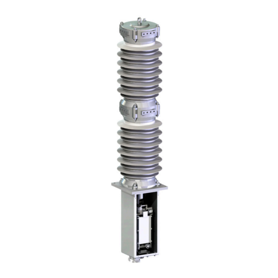
Page 6: Product Description
3. Product Description 3.1. Apparatus The FSK IIS+ apparatus are designed for outdoor installations and used in 50/60Hz railway traction power supply networks. They differ in particular by their fast breaking times. The vacuum circuit-breaker and load break switch types are equipped with a modern magnetically actuated mechanism instead of the conventional mechanical spring charged mechanism. - Page 7 Valve & protection for gas Place for contact filling wear check Optional cable exit Operations counter Position sensors ON/OFF Mechanical position indicator Manual tripping catch Magnetic actuator Heating resistance Cable exit Fig. 2 Apparatus drive unit, cover panel removed (shown only as an example) Control panel This is a general view.
- Page 8 “ signal. A set of dip switches and jumpers allows configuration of the functionality, according to customer requests. These settings are factory set and not to be changed at a later date without the agreement of ABB- Sécheron. Main features in detail: •...
- Page 9 Shown below is a schematic illustration of the MABS control card with the corresponding descriptions of the plug connectors. changes or manipulations to the card are to be performed without consultation with and confirmation from ABB KM1003 KM1005 KM1004 KM1007 Fig.
- Page 10 Plug connectors: • X1 : Position sensors of the magnetic actuator of Pole 1 • X2 : Position sensors of the magnetic actuator of Pole 2 • X3 : Connect to KM1001 of MABS 3.1.3. Control panel A control panel is connected to the MABS control card and commands the CB locally by two pushbuttons. A READY indicator LED is underneath the READY sign of the control panel and can be varied according to specific customer requests, e.g the colour scheme of the push buttons.
-
Page 11: Identification
Fig. 10 Manual opening mechanism 3.1.7. Manual opening from pole level To get access to the manual tripping catch, the threaded plug has to be removed. This can be done by means of a coin or screwdriver. After removing the plug, the manual tripping crank can be introduced into the hole in the front cover plate and the apparatus can be tripped by counter clockwise rotation of the hand crank Fig. - Page 12 The extension of the descriptions with numbers after the FSK designation are internal ABB descriptions and can vary from one apparatus to another. Fig. 13 Example of Identification Plates in German, English & French 3.2.2.
-
Page 13: Safety Precautions
4.2. Personnel Requirements Danger! This document describes the only official procedure approved by ABB Sécheron for performing the work described. ABB Sécheron refuses all responsibility with non-observance of these procedures During all works, such as e.g. the detailed planning, installation, disassembly, maintenance and commissioning of the apparatus, the persons performing the work are responsible for: •... -
Page 14: Transport & Storage
5. Transport & Storage On delivery of the apparatus, its condition is to be examined for transport damage. If a defect is observed (including damaged packaging), the manufacturer is to be informed immediately. The apparatus is delivered in a vertical or horizontal position on a Euro pallet or in a special transport crate. With vertical transport, the insulators are protected by a protective cover The apparatus must be transported with vacuum interrupter contacts in the open position 5.1. -
Page 15: Transport
With subsequent longer storage, the original packaging must be well re-sealed, in order to protect the apparatus against environmental influences. 5.4. Handling of transport damage In case of ABB Sécheron being responsible for transport, the customer is required to report any damage in within 7 days of receipt of the goods writing to ABB Sécheron... -
Page 16: Technical Data
6. Technical Data 6.1. Electrical Data Pole 6.1.1. Load break switch & Circuit breaker FSK1025 Designation Value Type: 1250 Frequency 50 Hz -60Hz Operating voltage 25 kV Number of phase 1 or 2 Rated voltage acc. To EN 50124-1 27.5 kV acc. -
Page 17: Mabs Control Card
6.1.2. Circuit breaker FSK1025 Designation Value Type: 2500 Frequency 50 Hz – 60Hz Operating voltage 25 kV Number of phase 1 or 2 Rated voltage acc. 27.5 kV To EN 50124-1 27.5 kV acc. To EN 60694 Rated power frequency withstand voltage (50Hz / 1 min) Phase to earth 105 kV... - Page 18 6.2.3. Binary Signal Inputs The used binary inputs can differ from project to project. Please refer to the valid wiring diagram. Designation Description Observation Remote Close Remote Open Auxiliary Open & Hardware driven Can be used in all operating modes (Global, Local,…) safe Open Input can be set as HW SAFE-Open.
- Page 19 6.2.5. Binary Signal Outputs The used binary inputs can differ from project to project. Please refer to the valid wiring diagram. Designation Description Observation CB Open This output is a copy of the “OPEN” position as determined by the sensor In the event of an error, the CPU activates the watchdog alarm CB Close This output is a copy of the “CLOSE”...
- Page 20 6.2.6. Electrical Characteristics of the Signal Outputs The outputs all consists of voltage free contacts with the following properties: Designation Value Voltage range 0 ... 280 V 0 ... 264 V Max. switching capacitance <6A, 250 VAC (ohmic) Max. making/breaking capacity <1500 VA/ DC Max.
- Page 21 6.2.8.2. I1002 Auxiliary-OFF, HW driven Safe–OFF, Delay On/Off, Undervoltage Behaviour Dip Switch I1002 Auxiliary-tripping For BI Y3 HW driven Safe–tripping For BI Y3 Delay for Opening/Closing Slow Close Toperation = 10ms delay For BI Y1 For BI Y2 / Y3 Slow Trip Toperation = 10ms delay Fast Close Toperation = 3ms delay...
- Page 22 6.2.8.4. I1004 Operating Mode LOCAL/GLOBAL/REMOTE Dip Switch I1004 Function LOCAL/GLOBAL LOCAL/REMOTE Table 11 Dip Switch I1004-5 6.2.8.5. I1004 Behaviour under Energy failure conditions (capacitor voltage) Dip Switch I1004 Function 2 3 4 Energy failure autotrip, active Energy failure autotrip, inactive Table 12 Dip Switch I1004-1 6.2.9.
-
Page 23: Weights And Dimensions
6.3. Weights and Dimensions The weight specifications refer to the apparatus / accessories and do not include any specifications for packaging. Designation Weight [kg] Outside Dimensions W*D*H [mm] Apparatus FSK 1025 120 (1) .-… 150 (2) 320 x 320 x 1900 Small Control box 400 x 320 x 440 Large Control box... -
Page 24: Assembly & Commissioning
7. Assembly & Commissioning DANGER! Before any activity, first check whether the work can be performed without risk and under the observance of the local valid regulations. In case of any doubt, contact your supervisors for clarification IMPORTANT! DANGER! We recommend that all work is carried out in a dry environment and with good lighting conditions IMPORTANT! DANGER! •... - Page 25 Fig. 17 (control box output) Fig. 18 (quick connection) 7.2.2.2. Version: Internal connection Every pole is linked to the control box with the “Umbilical Cord“. This shielded cable is prefabricated and factory tested. This cable is generally pre-installed with the control box. Allways disconnect the shielded multicore cable on the pole side The free end of the cable is equiped with a multiple connector and must simply be connected to the pole.
- Page 26 7.2.3. High-Voltage connections The connection of the high-voltage lines must be carried out in such a way that the forces from thermal expansion or line weight do not exceed the specified values. For this, either flexible connections or cable supports are to be provided. Max.
-
Page 27: Commissioning
7.2.4. Control Box connection The connection of the control box with the auxiliary power supply and the signal cables must be carried out in accordance with the electrical diagram applicable to the project. The terminal block in the control box is labelled with the corresponding indications. - Page 28 7.3.4. Control of the output power driver The status of the output power drivers is checked to verify that they are not in a status that could prevent switching operation. This is carried out: • On powering the equipment • Immediately after an opening operation •...
-
Page 29: Maintenance
DIN VDE/IEC as well as other higher-level directives. For the execution of maintenance and repair activities, it is recommended to consult ABB customer service. The intervals for inspection and maintenance are determined for some components (e.g. wearing parts) through defined criteria, such as switching frequency, duty time and number of short-circuit shutdowns. - Page 30 • Enter the number of switching operations indicated by the counter in the apparatus logbook • During operating voltage, no exterior discharges may appear on the surfaces of the electrical equipment. This can, for example, be determined by characteristic sounds, a clearly perceptible smell of ozone or visible glowing in the dark Important! Never put oil or grease in the guide of the moving contact of the vacuum switching chamber!
- Page 31 If the measured value drifts from the prescribed tolerance range, the vacuum switching chamber must be exchanged. For additional advice, contact ABB. This exchange including the necessary final tests must be performed by ABB specialists at ABB Sécheron. 100000 10000...
-
Page 32: Disposal
10.1. Procedure Before shipment of the materials to be repaired, we kindly request you contact ABB Sécheron, in order to clarify the shipment details, such as method of shipment, delivery address etc. For efficient processing of the case, we request as accurate a notification of the cause and circumstances of the damage as possible with the following information: •... -
Page 33: Spare Parts
10.3. Spare Parts We recommend, if necessary, that you use the following spare parts: Position sensor: ZUH.9057.00 Push button panel (Green-Close/Red-Open): 1VSR269194P0001 Push button panel (Red-O/ Green-I) : 1VSR269194P0003 Push button panel (White/Grey): 1VSR269194P0002 Capacitor: ZUI.9162.00 Vacuum switching chamber (VE1-250): ZUL.9038.00 Auxiliary switch block: On request... - Page 34 Ready LED goes cables out at the same time. Signal input Y3 is configured as “Safe OFF“ and Contact ABB Apparatus has been CPU is defective switched off by signal at Signal input Y6 “Lock in open“ is not active Close signal input and repeat procedure The “Auto-Reclose”...
-
Page 35: Customer Feedback File
Our aim is to make this document understandable and complete. To continuously improve the quality of our documentation, we would therefore welcome your opinion and would be pleased if you communicated suggestions for improvement to your local ABB or ABB Sécheron representatives. In this case please use this page and return it to: ABB Sécheron Ltd... - Page 36 We reserve the right to make technical changes or modify the contents of this document without prior notice. With regard to purchase orders, the agreed particulars shall prevail. ABB does not accept any responsibility whatsoever for potential errors or possible lack of information in this document.