Table of Contents
Advertisement
SERVICE MANUAL
This model is classified as a
This Service Manual describes replacement parts for the green product. When repairing this
green product, use the part(s) described in this manual and
For (*1) and (*2), refer to
SOLDER.
© TOSHIBA CORPORATION
file://C:\Documents and Settings\Alexsandr\Local Settings\Temp\Rar$EXa0.901\37H...
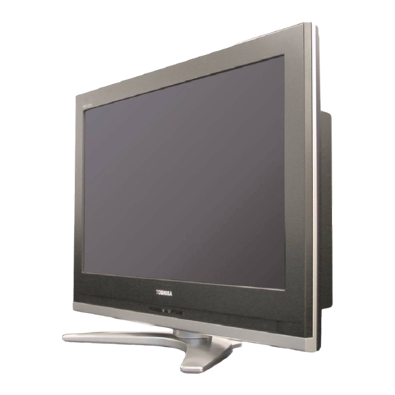
LCD Color Television
37HL57
green product
(*1), as indicated by the underlined serial number.
GREEN PRODUCT PROCUREMENT
Ver. 1.00
lead-free solder
(*2).
and
LEAD-FREE
Стр. 1 из 1
08.05.2015
Advertisement
Table of Contents

Related Manuals for Toshiba 37HL57


Summary of Contents for Toshiba 37HL57
- Page 1 This Service Manual describes replacement parts for the green product. When repairing this green product, use the part(s) described in this manual and lead-free solder (*2). For (*1) and (*2), refer to GREEN PRODUCT PROCUREMENT LEAD-FREE SOLDER. © TOSHIBA CORPORATION file://C:\Documents and Settings\Alexsandr\Local Settings\Temp\Rar$EXa0.901\37H... 08.05.2015...
-
Page 2: Green Product Procurement
Corporation recognizes environmental protection as a key management tasks, and is doing its utmost to enhance and improve the quality and scope of its environmental activities. In line with this, Toshiba proactively promotes Green Procurement, and seeks to purchase and use products, parts and materials that have low environmental impacts. -
Page 3: Lead-Free Solder
Стр. 1 из 1 LEAD-FREE SOLDER This product is manufactured using lead-free solder as a part of a movement within the consumer products industry at large to be environmentally responsible. Lead-free solder must be used in the servicing and repair of this product. WARNING: This product is manufactured using lead free solder. -
Page 4: Important Notice
Through WEB, ver. 6.5 has been released but with it, the linking function in this manual may not work properly. If ver. 6.5 has been installed, uninstall it and reinstall ver. 6.0. To get ver. 6.0, click the icon, or contact to the nearest Toshiba Service Centre for further assistance. Freezing windows opened (Cannot close the open windows) This may happen occasionally. - Page 5 Стр. 2 из 2 Continue to use by operating the windows. Precaution when opening the diagrams While opening the diagrams, the menu in the left frame changes its color to GRAY. This is an indication that the viewer is processing. With this condition, the menu indication color may stick to the GRAY color or Windows may freeze if clicking other menu.
- Page 6 Стр. 1 из 4 IMPORTANT NOTICE User Guide Autodesk® DWF™ Viewer is necessary to view drawings and to activate the functions of this system. Please download and install. When Windows XP SP2 is used, pop-up windows are limited by the enhanced security function and this sample may not work.
-
Page 7: Operating Environment
Стр. 2 из 4 Operating Environment : Pentium III or higher recommended Monitor : 1024 x 768 or higher resolution recommended file://C:\Documents and Settings\Alexsandr\Local Settings\Temp\Rar$EXa0.172\37H... 08.05.2015... - Page 8 Стр. 3 из 4 Mouse : A mouse with wheel recommended : Microsoft Windows 2000/XP Browser Microsoft Internet Explorer 6.0 or later Drawing viewer : Autodesk DWF Viewer 6.0 * Use the software following respective license terms and conditions. Note: In case of using this service manual with network connection, allocate its folder to the client PCs as network drive to avoid any possible malfunction.
- Page 9 Стр. 4 из 4 Layer Display Changing Function When any of the color buttons on the toolbar is clicked, it can be selected to display desired layer in its color or not to display each layer. This allows you to see the pattern layer only by setting other layers to "non-display".
- Page 10 WARRANTY OF MERCHANTABILITY AND FITNESS FOR A PARTICULAR PURPOSE. Toshiba shall not be liable for any damages, losses, expenses or costs, if any, incurred in connection with or as a result of use of any information or data provided herein.
-
Page 11: Service Mode
Стр. 1 из 18 ADJUSTMENT Service Mode Entering to Service Mode 1. Set VOLUME to minimum and press button once on remote control. ↓ ↓ ↓ ↓ 2. Press button again and hold button down. ↓ ↓ ↓ ↓ Service Mode display 3. - Page 12 Стр. 2 из 18 Displaying the Adjustment Menu Press MENU button on TV. Service Mode Press ↑ ↑ ↑ ↑ ↓ ↓ ↓ ↓ Press Adjustment Mode Key Function in the Service Mode The following key entry during display of adjustment menu provides special functions. CAUTION: Never try to perform initialization unless you have changed the memory IC.
-
Page 13: Setting & Adjusting Data
Стр. 3 из 18 Test signal selection Selection of the adjustment items (on TV or remote control) Change of the data value Volume +/- (on TV or remote control) Adjustment menu mode ON/OFF MENU button (on TV) Initialization of the memory (QA02) CALL + CH button on TV Reset the count of operating... - Page 14 Стр. 4 из 18 Item Name of adjustment Preset Data ← RCUT R CUT OFF ← GCUT G CUT OFF ← BCUT B CUT OFF ← RDRV R DRIVE ← GDRV G DRIVE ← BDRV B DRIVE ← BRTC BRIGHTNESS CENTER ←...
-
Page 15: Function Description
Стр. 5 из 18 Adjusting the Data Pressing of VOLUME +/- button will change the value of data in the range from 00H to FFH. The variable range depends on the adjusting item. I2C Bus Off Turn off I2C communication between IC700 and IC400. 1) Press and hold the CALL button on the remote control, then press the Volume button on the TV. - Page 16 OPT5 value as table below. Panel option data Series Model name Panel vendor OPT4 value OPT5 value HL57 26HL57 SAMSUNG 0x06 0x03 32HL57 SHARP 0x02 0x05 37HL57 AUO AMVA 0x05 0x06 SHARP 0x02 0x06 42HL57 0x01 0x07 0x03 0x07 Ex.
- Page 17 Стр. 7 из 18 Convert from Bit (Binary) to Hex The table for converting from bit (D7-D0) to hex (0x**). BIT (Binary) High nibble Low nibble E.g. If Bit D7-0 = 0101 1010, Hex data is 0x5A. file://C:\Documents and Settings\Alexsandr\Local Settings\Temp\Rar$EXa0.108\37H... 08.05.2015...
- Page 18 Стр. 8 из 18 Exit from Service Mode Pressing POWER button to turn off the TV once. Initialization of Memory Data of QA02 and Setting Data of Signal Unit After replacing QA02 or signal board, the following initialization is required. CAUTION: Never attempt to initialize the data unless QA02 has been replaced.
-
Page 19: Self-Diagnostic Function
Стр. 9 из 18 Red raster Green raster Blue raster All Black All White Self Diagnostic Function 1. Press "9" button on remote control during display of adjustment menu in the service mode. The diagnosis will begin to check if interface among IC's is executed properly. 2. - Page 20 Стр. 10 из 18 (1) Firmware : Version information of microprocessor Series name (AAAA) and market area (BB) and software program version (0000) (2) Time : Total hour of turn the TV on. (Unit : H) (3) BL_STATUS : Counter for saving BackLight on error. This value is counted till 99 (Decimal).
- Page 21 Стр. 11 из 18 (S-VIDEO/Composite) (Component) HDMI 1 HDMI 2 Version Check Mode 1. Press "9" button twice on remote control during display of adjustment menu in the service mode. The version of main MPU will be checked. 2. During Version Check, the following displays are shown. * Version check display and Item are subject to the models.
- Page 22 (5) HDMI ID : HDMI ID information : Display 4 byte data. (6) SW Ver Version information of DB software as Toshiba release. (Only digital model.) (7) MW Ver Left side is Application and UI version information of DB software. (Only digital model.)
- Page 23 Стр. 13 из 18 (8) A/D Adjust A/D adjustment item. --MAIN : It's enable only in double Window model. A/D adjustment status of main picture. --PIP : It's enable only in double Window model. A/D adjustment status of sub picture. --COMP : Component input --PC : PC input...
-
Page 24: Screen Size
Стр. 14 из 18 * Status check display and Item are subject to the models. (1) MAIN : Main source information : Display RF position number (0 - 99) on the main screen, or Input Source (EXT1/2/3/HDMI etc.) (2) MAIN FORMAT : Display Video and PC format information (3) MAIN PLL : Main PLL information : Display 1 byte data at five. - Page 25 Стр. 15 из 18 Cinema 2 Super Live 1 Cinema 1 Subtitle 14:9 Note: Exact Scan is shown only for 1080p panel model with video input mode except pc. (8) OTHER STATUS : Other status information : Display three numbers of 2 byte data. Setting Hotel Mode Enter to service mode and select Hotel Mode menu by pressing P or P .
- Page 26 Стр. 16 из 18 language. (Display the language only) (tuning SETUP MENU) D1 (bit1) Disable SETUP MENU Disable Enable D0 (bit0) HOTEL Mode On (Enable the setting of D1 from to D7) (Normal) VOLUX Set VOLUX as following. 1) Set speaker volume to 100. (Any value is OK, but 100 is better to check sound level.) 2) Down value of VOLUX until finding suitable sound volume level.
-
Page 27: Led Indication
Стр. 17 из 18 D0 (bit0) Value above 100 is no effect. OPT8 FUNCTION DESCRIPTION 0 (Normal) D7 (bit7) ~ - (no use) D3 (bit3) D2 (bit2) Enable mode that picture mode will be set in Enable Disable forced when turn ON the main power (Display the language only) D1 (bit1) ~... - Page 28 Стр. 18 из 18 file://C:\Documents and Settings\Alexsandr\Local Settings\Temp\Rar$EXa0.108\37H... 08.05.2015...
- Page 29 Стр. 1 из 2 FUNCTION AND OPERATION TV Front and Side Panel Control and Connection file://C:\Documents and Settings\Alexsandr\Local Settings\Temp\Rar$EXa0.219\37H... 08.05.2015...
- Page 30 Стр. 2 из 2 file://C:\Documents and Settings\Alexsandr\Local Settings\Temp\Rar$EXa0.219\37H... 08.05.2015...
-
Page 31: Function And Operation
Стр. 1 из 3 FUNCTION AND OPERATION Learning about the Remote Control file://C:\Documents and Settings\Alexsandr\Local Settings\Temp\Rar$EXa0.732\37H... 08.05.2015... - Page 32 Стр. 2 из 3 file://C:\Documents and Settings\Alexsandr\Local Settings\Temp\Rar$EXa0.732\37H... 08.05.2015...
- Page 33 Стр. 3 из 3 file://C:\Documents and Settings\Alexsandr\Local Settings\Temp\Rar$EXa0.732\37H... 08.05.2015...
- Page 34 Стр. 1 из 3 FUNCTION AND OPERATION Programming Channel into the TV's Channel Memory Programming Channel Automatically file://C:\Documents and Settings\Alexsandr\Local Settings\Temp\Rar$EXa0.165\37H... 08.05.2015...
- Page 35 Стр. 2 из 3 file://C:\Documents and Settings\Alexsandr\Local Settings\Temp\Rar$EXa0.165\37H... 08.05.2015...
- Page 36 Стр. 3 из 3 Manually Adding and Deleting Channel in the Channel Memory file://C:\Documents and Settings\Alexsandr\Local Settings\Temp\Rar$EXa0.165\37H... 08.05.2015...
-
Page 37: Safety Instruction
Handling the LCD Module Стр. 1 из 4 SAFETY INSTRUCTION Handling the LCD Module Safety Precaution In the event that the screen is damaged or the liquid crystal (fluid) leaks, do not breathe in or drink this fluid. Also, never touch this fluid. Such actions could cause toxicity or skin irritation. If this fluid should enter the mouth, rinse the mouth thoroughly with water. - Page 38 Handling the LCD Module Стр. 2 из 4 3. If the panel surface becomes soiled, wipe with cotton or a soft cloth. If this does not remove the soiling, breathe on the surface and then wipe again. If the panel surface is extremely solied, use a CRT cleaner as a cleaner. Wipe off the panel surface by drop the cleaner on the cloth.
- Page 39 Handling the LCD Module Стр. 3 из 4 6. CMOS-LSI circuitry is used in the LCD module, so avoid damage due to static electricity. When handling the module, use a wrist ground or anchor ground. 7. Do not expose the LCD module to direct sunlight or strong ultraviolet rays for an extended period of time.
- Page 40 Handling the LCD Module Стр. 4 из 4 10. When transporting the LCD module, do not use packing containing epoxy resin (amine) or silicon resin (alcohol or oxim). The gas generated by these materials can cause loss of polarity. file://C:\Documents and Settings\Alexsandr\Local Settings\Temp\Rar$EXa0.846\37H... 08.05.2015...
- Page 41 U02A LOW-B U01A POWER U03D U03A U04A AV-TERM SIGNAL U03B Front-AV U03C...
-
Page 42: Safety Precaution
SAFETY INSTRUCTION [LCD] USA Стр. 1 из 3 SAFETY INSTRUCTION WARNING: BEFORE SERVICING THIS CHASSIS, READ THE "SAFETY PRECAUTION" AND "PRODUCT SAFETY NOTICE" INSTRUCTIONS BELOW. Safety Precaution WARNING: SERVICING SHOULD NOT BE ATTEMPTED BY ANYONE UNFAMILIAR WITH THE NECESSARY PRECAUTIONS ON THIS RECEIVER. THE FOLLOWING ARE THE NECESSARY PRECAUTIONS TO BE OBSERVED BEFORE SERVICING THIS CHASSIS. - Page 43 SAFETY INSTRUCTION [LCD] USA Стр. 2 из 3 inflammability, voltage resistance, etc. therefore, use only replacement parts that have these same characteristics. Use only the specified parts when the mark is indicated in the circuit diagram or parts list. 7. Parts mounting and routing dressing of wirings should be the same as that used originally.
-
Page 44: Product Safety Notice
SAFETY INSTRUCTION [LCD] USA Стр. 3 из 3 limit constitutes a potential shock hazard and must be corrected immediately. Product Safety Notice Many electrical and mechanical parts in this chassis have special safety-related characteristics. These characteristics are often passed unnoticed by a visual inspection and the protection afforded by them cannot necessarily be obtained by using replacement components rated for higher voltage, wattage, etc. -
Page 45: Specification
Стр. 1 из 3 SPECIFICATION file://C:\Documents and Settings\Alexsandr\Local Settings\Temp\Rar$EXa0.613\37H... 08.05.2015... - Page 46 Стр. 2 из 3 file://C:\Documents and Settings\Alexsandr\Local Settings\Temp\Rar$EXa0.613\37H... 08.05.2015...
- Page 47 Стр. 3 из 3 file://C:\Documents and Settings\Alexsandr\Local Settings\Temp\Rar$EXa0.613\37H... 08.05.2015...
- Page 58 AV BOARD SIGNAL BOARD PANEL FLI8548 CORTEZ Plus w HDMI VBI Data Processor TV/CVBS/Y /C / R/G/B/H/V Y/Cb/Cr Y/Cb/Cr PANEL I/F CVBS EXT1 Y DETECT S DETECT DCDi Video Analog MADi Decoder Front S Y/C Scaling Standby EXT2 CVBS uCON (front) (16port) LVDS...
-
Page 59: Schematic Diagram
Стр. 1 из 2 SCHEMATIC DIAGRAM Precaution WARNING: BEFORE SERVICING THIS CHASSIS, READ THE "X-RAY RADIATION PRECAUTION" FOR DIRECT VIEW CTV ONLY, "SAFETY PRECAUTION" AND "PRODUCT SAFETY NOTICE" OF THIS MANUAL. CAUTION: The international hazard symbols " " in the schematic diagram and the parts list designate components which have special characteristics important for safety and should be replaced only with types identical to those in the original circuit... - Page 60 Стр. 2 из 2 All capacitors are ceramic 50 V, unless otherwise noted as the following marks. = Electrolytic capacitor = Mylar capacitor 3. The parts indicated with " " have special characteristics, and should be replaced with identical parts only. 4.
- Page 109 Стр. 1 из 2 CABINET Stand Exploded View A425 A426 A427 A428 A429 file://C:\Documents and Settings\Alexsandr\Local Settings\Temp\Rar$EXa0.942\37H... 08.05.2015...
- Page 110 Стр. 2 из 2 file://C:\Documents and Settings\Alexsandr\Local Settings\Temp\Rar$EXa0.942\37H... 08.05.2015...
- Page 111 Accessory Стр. 1 из 1 Accessory Location Parts No. Description K902 75002548 REMOCON HAND UNIT, CT-90262 Y101 75007249 OWNERS MANUAL, E/F Y109 23945015 BAG, POLYETHYLENE COVER 250X400 Y170 23845800 HOLDER, WIRE, NYLON66 D6.8 file://C:\Documents and Settings\Alexsandr\Local Settings\Temp\Rar$EXa0.160\37H... 08.05.2015...
- Page 112 Cabinet Стр. 1 из 1 Cabinet Location Parts No. Description A201 75007394 CESE/COVER/LID FRONT BEZEL ASSY, FRONT BEZEL ASSY A380 23717240 SCREW, BITTB3X10SZN A401 75006099 BACK COVER ASSY A411 23717267 SCREW, BITTB4X16 SBN A412 23717214 SCREW, BITTB3X12SBN A420 75007250 STAND KIT, FIX AG A425 75006746 STAND PART, FIX BKT ASSY...
- Page 113 Miscellaneous Стр. 1 из 1 Miscellaneous Location Parts No. Description B001 75006018 LCD PANEL, G7AUO37V5, T370XW02 V5 MZ01 75006512 WIRE HARNESS, LVDS, V90A00011800 P801 75002678 POWER CORD, INQ2682(1) PJ22B 75002683 CONNECTOR, 1MM PITCH B TO B, 237702150K4 PP08 23974994 BAND, KESSOKU PP09 23974994 BAND, KESSOKU...
- Page 114 Packing Стр. 1 из 1 Packing Location Parts No. Description A701A 75007395 CARTON TOP CASE, TOP CASE A701B 75006100 CARTON BOX, BOTTOM A702A 75006101 PAD, TOP PACKING A702B 75006102 PAD, BOTTOM PACKING A703 23945216 BAG, LAMIFILM A705 23518043 PACKING, JOINT A706 75006559 CARTON, O/M CASE...
-
Page 115: Parts List
Стр. 1 из 2 PARTS LIST Precaution WARNING: BEFORE SERVICING THIS CHASSIS, READ THE "X-RAY RADIATION PRECAUTION" FOR DIRECT VIEW CTV ONLY, "SAFETY PRECAUTION" AND "PRODUCT SAFETY NOTICE" OF THIS MANUAL. CAUTION: The international hazard symbols " " in the schematic diagram and the parts list designate components which have special characteristics important for safety and should be replaced only with types identical to those in the original circuit... - Page 116 Стр. 2 из 2 : Electrolytic : Metal Film : Fusible Resistor All CD and PF capacitors are ±5 %, 50 V and all resistor, ±5 %, 1/6 W unless otherwise noted. file://C:\Documents and Settings\Alexsandr\Local Settings\Temp\Rar$EXa0.159\37H... 08.05.2015...
- Page 117 U01A POWER (PE0345) Стр. 1 из 4 U01A POWER (PE0345) Parts Location Description U01A 75007242 PC BOARD ASSY, PE0345A1, POWER C801 76503510 CAPACITOR, PLASTIC FILM, LE224-C C802 76503510 CAPACITOR, PLASTIC FILM, LE224-C C803 76168103 CAPACITOR, PLASTIC FILM, 400V 0.22UF J C804 76214103 CAPACITOR, CERAMIC DISC, 500V B 0.01UF K C805...
- Page 118 U01A POWER (PE0345) Стр. 2 из 4 CE29 76105331 CAPACITOR, CERAMIC CHIP, 50V CH 330PF J CE43 76092883 CAPACITOR, CERAMIC CHIP, 50V B 0.1UF K CE82 76676470 CAPACITOR, ELECTROLYTIC, 100V 47UF M CE85 76073178 CAPACITOR, ELECTROLYTIC, 25V 3300UF M D801 23362200 DIODE, D5SB60, 7009F07 D801B 23717240 SCREW, BITTB3X10SZN...
- Page 119 U01A POWER (PE0345) Стр. 3 из 4 FE72 23144251 FUSE, AXIAL, 125V 1A FE75 23144227 FUSE, CARTRIDGE 5.2X20, 125V 5A L801 23217834 TRANSFORMER, CHOKE, TPW2078AS L802 23217792 TRANSFORMER, CHOKE, TPW2072AS L803 23103304 FERRITE CHOKE, TEM2011AA L804 23103304 FERRITE CHOKE, TEM2011AA L805 23103304 FERRITE CHOKE, TEM2011AA L806...
- Page 120 U01A POWER (PE0345) Стр. 4 из 4 R815 76552100 RESISTOR, OXIDE METAL FILM, 1/2W 10 OHM J R816 76011331 RESISTOR, CHIP, 1/20W 330 OHM J R817 76382823 RESISTOR, OXIDE METAL FILM, 1W 82K OHM J R821 76553680 RESISTOR, OXIDE METAL FILM, 1W 68 OHM J R828 76383103 RESISTOR, OXIDE METAL FILM, 2W 10K OHM J R853...
- Page 121 U02A LOW_B (PE0347) Стр. 1 из 3 U02A LOW_B (PE0347) Location Parts No. Description U02A 75007393 PWU, LOWB, PE0347B1 CE100 76092538 CAPACITOR, CERAMIC CHIP, 10V F 1UF Z CE102 76109102 CAPACITOR, CERAMIC CHIP, 50V B 1000PF K CE150 76092179 CAPACITOR, CERAMIC CHIP, 25V B 0.22UF K CE151 76092179 CAPACITOR, CERAMIC CHIP, 25V B 0.22UF K...
- Page 122 U02A LOW_B (PE0347) Стр. 2 из 3 P806B 23713759 PLUG, 8P 2.5MM G, B8B-EH-F1-TV4 P807B 23713757 PLUG, 6P 2.5MM G, B6B-EH-F1-TV4 PG02 23165495 EARTH TERMINAL, MET31-0332 QE100 23205443 TRANSISTOR, 2SA1162-Y(F) QE101 23205446 TRANSISTOR, 2SC2412K, Q T146 QE102 23205446 TRANSISTOR, 2SC2412K, Q T146 QE103 23205327 TRANSISTOR, RN1406(F)
- Page 123 U02A LOW_B (PE0347) Стр. 3 из 3 RE200 76000445 CHIP JUMPER, 1608TYPE RE31 76011103 RESISTOR, CHIP, 1/20W 10K OHM J RE32 76011104 RESISTOR, CHIP, 1/20W 100K OHM J RE33 76553122 RESISTOR, OXIDE METAL FILM, 1W 1.2K OHM J RE34 76011473 RESISTOR, CHIP, 1/20W 47K OHM J RE35 76011223...
- Page 124 U03A AV_TERMINAL (PE0329) Стр. 1 из 5 Loading ... Location Parts No. Description U03A 75007244 PC BOARD ASSY, PE0329A1, AV_TERMINAL C101 76092730 CAPACITOR, CERAMIC CHIP, 16V B 0.1UF K C102 76762471 CAPACITOR, ELECTROLYTIC, 10V 470UF M C103 76092730 CAPACITOR, CERAMIC CHIP, 16V B 0.1UF K C104 76092730 CAPACITOR, CERAMIC CHIP, 16V B 0.1UF K...
- Page 125 U03A AV_TERMINAL (PE0329) Стр. 2 из 5 C8001 76668102 CAPACITOR, ELECTROLYTIC, 35V 1000UF M CA01 76092538 CAPACITOR, CERAMIC CHIP, 10V F 1UF Z CA02 76105101 CAPACITOR, CERAMIC CHIP, 50V CH 100PF J CA03 76100104 CAPACITOR, CERAMIC CHIP, 25V F 0.1UF Z CA19 76092538 CAPACITOR, CERAMIC CHIP, 10V F 1UF Z...
- Page 126 U03A AV_TERMINAL (PE0329) Стр. 3 из 5 CG32 76092726 CAPACITOR, CERAMIC CHIP, 10V B 2.2UF K CG33 76092726 CAPACITOR, CERAMIC CHIP, 10V B 2.2UF K CG34 76092730 CAPACITOR, CERAMIC CHIP, 16V B 0.1UF K CG35 76669100 CAPACITOR, ELECTROLYTIC, 50V 10UF M CG36 76669100 CAPACITOR, ELECTROLYTIC, 50V 10UF M...
- Page 127 U03A AV_TERMINAL (PE0329) Стр. 4 из 5 GR03 76000445 CHIP JUMPER, 1608TYPE GR04 76000445 CHIP JUMPER, 1608TYPE GR09 23362042 DIODE, ZENER, UDZS6.8B GR17 23362042 DIODE, ZENER, UDZS6.8B GR18 23362042 DIODE, ZENER, UDZS6.8B GR37 76000445 CHIP JUMPER, 1608TYPE GR603 76000445 CHIP JUMPER, 1608TYPE H001 75005730 TUNER, ENG36E02KF...
- Page 128 U03A AV_TERMINAL (PE0329) Стр. 5 из 5 Q663 23205347 TRANSISTOR, KTC4075Y/P Q670 23085826 IC, TA8246AHQ(5) Q670B 23717240 SCREW, BITTB3X10SZN Q671 23205424 TRANSISTOR, KTC2875B/P Q672 23205424 TRANSISTOR, KTC2875B/P Q673 23205357 TRANSISTOR, KTA1504S Y/P QA01 75006034 IC, T5CB5-6NP1(F, JZ) QA03 75001878 IC, TC7SH126FU(TE85L, F) QA72 23205347 TRANSISTOR, KTC4075Y/P...
- Page 129 U03B FRONT-AV (PE0329) Стр. 1 из 1 U03B FRONT-AV (PE0329) Location Parts No. Description U03B 75007245 PC BOARD ASSY, PE0329A2, FRONT_AV CC11 76109102 CAPACITOR, CERAMIC CHIP, 50V B 1000PF K CC12 76109102 CAPACITOR, CERAMIC CHIP, 50V B 1000PF K CV121 76109103 CAPACITOR, CERAMIC CHIP, 50V B 0.01UF K GR605...
- Page 130 U03C LED (PE0329) Стр. 1 из 1 U03C LED (PE0329) Location Parts No. Description U03C 75007246 PC BOARD ASSY, PE0329A3, LED CB02 76619102 CAPACITOR, ELECTROLYTIC CHIP, 16V 47UF M CB03 76100104 CAPACITOR, CERAMIC CHIP, 25V F 0.1UF Z CB04 76100104 CAPACITOR, CERAMIC CHIP, 25V F 0.1UF Z CB05 76619157...
- Page 131 U03D KEY (PE0329) Стр. 1 из 1 U03D KEY (PE0329) Location Parts No. Description U03D 75007247 PC BOARD ASSY, PE0329A4, KEY GA01 23362042 DIODE, ZENER, UDZS6.8B GA02 23362042 DIODE, ZENER, UDZS6.8B GA03 23362042 DIODE, ZENER, UDZS6.8B PA42B 23713938 CONNECTOR, B5B-PH-K-S(LF) RA71 76011683 RESISTOR, CHIP, 1/20W 68K OHM J...
- Page 132 U04AS SIGNAL (PE0251) Стр. 1 из 8 Loading ... Location Parts No. Description U04AS 75007338 PC BOARD ASSY, PE0251B1, SIGNAL C2000 V03GD0000572 CHIP CERAMIC CAPACITOR (1608) C2001 V03GD0000572 CHIP CERAMIC CAPACITOR (1608) C2002 V03GD0000572 CHIP CERAMIC CAPACITOR (1608) C2003 V03GD0000572 CHIP CERAMIC CAPACITOR (1608) C2004 V03GD0000572 CHIP CERAMIC CAPACITOR (1608) C2005...
- Page 133 U04AS SIGNAL (PE0251) Стр. 2 из 8 C3420 V03GD0000572 CHIP CERAMIC CAPACITOR (1608) C3421 V03GD0000538 CHIP CERAMIC CAPACITOR (1608) C3446 V03GD0000719 CHIP CERAMIC CAPACITOR (1608) C360 V03GD0000572 CHIP CERAMIC CAPACITOR (1608) C361 V03GD0001318 CHIP CERAMIC CAPACITOR (2012) C362 V03GD0001318 CHIP CERAMIC CAPACITOR (2012) C370 V03GD0000741 CHIP CERAMIC CAPACITOR (3216) C371...
- Page 134 U04AS SIGNAL (PE0251) Стр. 3 из 8 C442 V03GD0000572 CHIP CERAMIC CAPACITOR (1608) C451 V03GD0000572 CHIP CERAMIC CAPACITOR (1608) C453 V03GD0000574 CHIP CERAMIC CAPACITOR (1608) C454 V03GD0000538 CHIP CERAMIC CAPACITOR (1608) C455 V03GD0000538 CHIP CERAMIC CAPACITOR (1608) C458 V03GD0000572 CHIP CERAMIC CAPACITOR (1608) C459 V03GD0001131 CHIP CERAMIC CAPACITOR (2012) C460...
- Page 135 U04AS SIGNAL (PE0251) Стр. 4 из 8 C790 V03GD0000572 CHIP CERAMIC CAPACITOR (1608) C7900 V03GD0000572 CHIP CERAMIC CAPACITOR (1608) C7901 V03GD0000572 CHIP CERAMIC CAPACITOR (1608) C7902 V03GD0000572 CHIP CERAMIC CAPACITOR (1608) C7903 V03GD0000572 CHIP CERAMIC CAPACITOR (1608) C7904 V03GD0000572 CHIP CERAMIC CAPACITOR (1608) C7905 V03GD0000572 CHIP CERAMIC CAPACITOR (1608) C7906...
- Page 136 U04AS SIGNAL (PE0251) Стр. 5 из 8 C7940 V03GD0000572 CHIP CERAMIC CAPACITOR (1608) C7941 V03GD0000572 CHIP CERAMIC CAPACITOR (1608) C7942 V03GD0000572 CHIP CERAMIC CAPACITOR (1608) C7943 V03GD0000572 CHIP CERAMIC CAPACITOR (1608) C7944 V03GD0000572 CHIP CERAMIC CAPACITOR (1608) C7945 V03GD0000572 CHIP CERAMIC CAPACITOR (1608) C7946 V03GD0001131 CHIP CERAMIC CAPACITOR (2012) C7947...
- Page 137 U04AS SIGNAL (PE0251) Стр. 6 из 8 C7982 V03GD0000572 CHIP CERAMIC CAPACITOR (1608) C7983 V03GD0000572 CHIP CERAMIC CAPACITOR (1608) C7984 V03GD0000572 CHIP CERAMIC CAPACITOR (1608) C7985 V03GD0000572 CHIP CERAMIC CAPACITOR (1608) C7986 V03GD0000572 CHIP CERAMIC CAPACITOR (1608) C7987 V03GD0000572 CHIP CERAMIC CAPACITOR (1608) C7988 V03GD0000572 CHIP CERAMIC CAPACITOR (1608) C7989...
- Page 138 U04AS SIGNAL (PE0251) Стр. 7 из 8 C9223 V03GD0000572 CHIP CERAMIC CAPACITOR (1608) C9224 V03GD0000558 CHIP CERAMIC CAPACITOR (1608) C923 V03GD0000572 CHIP CERAMIC CAPACITOR (1608) C924 V03GD0000572 CHIP CERAMIC CAPACITOR (1608) C951 V03GD0001126 CHIP CERAMIC CAPACITOR (1608) C953 V03GD0001126 CHIP CERAMIC CAPACITOR (1608) CN320 75001875 CONNECTOR HDMI 1.0MM 19P...
- Page 139 U04AS SIGNAL (PE0251) Стр. 8 из 8 FL301 V05A000002Q0 COIL FL302 V05A000002Q0 COIL FL303 V05A000002Q0 COIL FL304 75003116 FILTER CHIP BEAD INDUCTOR 60OH FL305 75003411 FILTER CHIP BEAD INDUCTOR 220O FL306 75003411 FILTER CHIP BEAD INDUCTOR 220O FL310 V01GD0001702 CHIP JUMPER 1608TYPE FL326 75003115 FILTER CHIP BEAD INDUCTOR 220O...