Table of Contents
Advertisement
Advertisement
Table of Contents

Related Manuals for Perkins 1000 Series


Summary of Contents for Perkins 1000 Series
- Page 1 TPD1329E, Issue 3 July 2000 User’s Handbook Perkins 1000 Series AA to AH YA to YD...
- Page 2 This publication is written in Perkins Approved Clear English Chapters 1 General information 2 Engine views 3 Operation instructions 4 Preventive maintenance 5 Engine fluids 6 Fault diagnosis 7 Engine preservation 8 Parts and service 9 General data The following pages contain a detailed table of contents...
-
Page 3: Table Of Contents
Perkins companies ........ - Page 4 How to renew an atomiser ..........28 How to eliminate air from the fuel system .
-
Page 5: General Information
General Information Introduction The Perkins 1000 Series industrial and agricultural Danger is indicated in the text by two methods: engines are the latest developments from Perkins Warning! This indicates that there is a possible Engines Limited a world leader in the design and danger to the person. -
Page 6: How To Care For Your Engine
Perkins distributors have this type of personnel available. You can also obtain parts and service from your Perkins distributor. If you do not know the address of your nearest distributor, enquire at one of the Perkins companies listed on page 8. -
Page 7: Engine Identification
Engine identification The 1000 Series consists of a range of both four and six cylinder engines. Each range has four basic engine types, naturally aspirated, compensated, turbocharged and turbocharged with an intercooler. There are different model variations within each range. Identification of the various models is by a... -
Page 8: Perkins Companies
Italy Motori Perkins S.p.A., In addition to the above companies, there are Via Socrate 8, Perkins distributors in most countries. Perkins 22070 Casnate con Bernate (Como), Italy. Engines Company Limited., Peterborough or one Telephone: 0039 031 4633466 / 031 4633488 of the above companies can provide details. -
Page 9: General Safety Precautions
Do not operate the engine if a safety guard has Fit only genuine Perkins parts. been removed. Do not remove the filler cap or any component of... - Page 10 This page is intentionally blank...
-
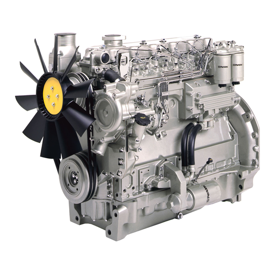
Page 11: Engine Views
Engine views Introduction Perkins engines are built for specific applications and the views which follow do not necessarily match your engines specification. Location of engine parts Front and left side of the YB engine (A) 1 Filler cap for the lubricating oil... - Page 12 Rear and right side of the YB engine (A) 14 Induction manifold 20 Flywheel housing 15 Alternator 21 Flywheel 16 Lubricating oil filter 22 Turbocharger 17 Fuel lift pump 23 Exhaust manifold 18 Lubricating oil sump 24 Rear lift bracket 19 Starter motor A0315...
-
Page 13: Operation Instructions
Perkins engines can be equipped with various cold starting systems. For the 1000 Series engines these systems are: Fuelled starting aid An electrically operated device which ignites a specific amount of diesel fuel in the induction manifold in order to heat the induction air. - Page 14 How to start a warm engine 1 If the engine is equipped with a manual stop control, ensure that it is in the "run" position. 2 Adjust the engine speed control to the quarter open position. 3 Turn the start key to the "HS" or "S" position (A) or (B) to engage the starter motor.
- Page 15 How to start a cold engine with manually operated How to start a cold engine with KBi or electrically Start Pilot operated Start Pilot Caution: Start Pilot equipment must not be used with Caution: KBi equipment must not be used with heater type starting aids such as the fuelled starting heater type cold starting aids such as the fuelled starting aid.
-
Page 16: How To Stop The Engine
Changes to the settings of the engine start key to the "O" position (page 14/A or B) fuel injection pump must be made by a Perkins or operate the manual stop control. If a manual stop distributor or by an approved distributor for the fuel control is used, ensure that the control returns to the injection pump. -
Page 17: Preventive Maintenance
Preventive maintenance Preventive maintenance periods These preventive maintenance periods apply to average conditions of operation. Check the periods given by the manufacturer of the equipment in which the engine is installed. Use the periods which are shortest. When the operation of the engine must conform to the local regulations these periods and procedures may need to be adapted to ensure correct operation of the engine. -
Page 18: Schedules
Schedules The schedules which follow must be applied at the interval (hours or months) which occur first. A First service at 20/40 hours D Every 400 hours or 12 months B Every day or every 8 hours E Every 2000 hours C Every 200 hours or 6 months A B C D E Operation... - Page 19 Schedules The schedules which follow must be applied at the interval (hours or months) which occur first. A First service at 20/40 hours D Every 400 hours or 12 months B Every day or every 8 hours E Every 2000 hours C Every 200 hours or 6 months A B C D E Operation...
-
Page 20: How To Drain The Cooling System
How to drain the cooling system Warnings! Discard the used coolant in a safe place and in accordance with local regulations. Do not drain the coolant while the engine is still hot and the system is under pressure because dangerous hot coolant can be discharged. 1 Ensure that the machine is on level ground. -
Page 21: How To Check The Specific Gravity Of The Coolant
Note: If it is necessary to fill or replenish the coolant system in service, mix the coolant to the correct strength before it is added to the coolant system. Perkins POWERPART antifreeze with a concentration of 50% will give protection against frost to a temperature of -35 C (-31 F). -
Page 22: How To Check The Drive Belt(S)
How to check the drive belt(s) Renew a belt if it is worn or damaged. If twin belts are fitted, they must be renewed together. To ensure maximum belt life, it is recommended that a belt tensioner gauge is used to check the belt tension. -
Page 23: How To Clean The Gauze Strainer Of The Fuel Lift Pump
How to clean the gauze strainer of the fuel lift pump 1 Release the fastener (A2) and remove the cover and the joint (A3) from the top of the fuel lift pump (A4). Remove the gauze strainer (A1). On some turbocharged engines, it will be necessary to remove the small heat shield which is fitted above the pump. -
Page 24: How To Renew The Element(S) Of The Fuel Filter
Cautions: It is important that only the genuine Perkins parts are used. The use of a wrong canister or element can damage the fuel injection pump. Do not allow dirt to enter the fuel system. Before a... -
Page 25: How To Renew The Element(S) Of The Separate Element Type
How to renew the element(s) of the separate element type Caution: It is important that only the genuine Perkins fuel filter element is used. The use of a wrong element can cause damage to the fuel injection pump. 1 Clean the outside surfaces of the fuel filter assembly. -
Page 26: How To Renew The Filter Canister Of The Canister Fuel Filter
How to renew the filter canister of the canister fuel filter 1 Thoroughly clean the outside surfaces of the fuel filter assembly. 2 Loosen the drain device at the bottom of the filter (A1) and allow the water/fuel to drain into a suitable container. -
Page 27: How To Renew The Canister Of The Quick Release Fuel Filter
How to renew the canister of the quick release fuel filter 1 Thoroughly clean the outside surfaces of the filter assembly. 2 Loosen the drain device (A4) , if one is fitted, at the bottom of the canister and allow the water/fuel to drain into a suitable container. -
Page 28: Atomiser Fault
Atomiser fault Warnings! If your skin comes into contact with high-pressure fuel, obtain medical assistance immediately. Keep away from moving parts during engine operation. Some moving parts cannot be seen clearly while the engine runs. An atomiser fault can cause an engine misfire. In order to find which atomiser is defective, operate the engine at a fast idle speed. -
Page 29: How To Eliminate Air From The Fuel System
How to eliminate air from the fuel system There are two methods to eliminate air from the fuel system according to the type of fuel injection pump fitted: The standard method is used where the fuel injection pump has vent screws (A1/2) and (B1). The self-vent method is used where the fuel injection pump has a self-vent feature. - Page 30 Standard method to eliminate air from the fuel system 1 Loosen the vent plug on the top of the twin element fuel filter (A1). If a single element filter is used, loosen the banjo connection bolt which is fitted on the top of the filter (B1).
- Page 31 Caution: Use a spanner on the flats (A1) of the fuelled starting aid to prevent its movement when the union nut (A2) is loosened and tightened. 5 If the pipe to the fuelled starting aid has been drained, loosen the union nut (A2) at the fuelled starting aid and operate the lift pump (C) until fuel, free from air, comes from the connection.
- Page 32 Self-vent method Fuel injection pumps used on some Lucas and all Stanadyne fuel injection pumps will automatically remove air from the fuel system. Vent screws are not fitted to these pumps. Caution: Although these fuel injection pumps will eliminate air automatically, use the procedure that follows to remove air from the fuel system if the system is drained or a major component is removed: Ensure that fuel has been added to the tank or that...
- Page 33 Cautions: Do not tighten the union nuts of the high-pressure pipes more than the recommended torque tension. If there is a leakage from the union nut, ensure that the pipe is correctly aligned with the atomiser inlet. Do not tighten the atomiser union nut more, as this can cause a restriction at the end of the pipe.
-
Page 34: How To Renew The Lubricating Oil Of The Engine
How to renew the lubricating oil of the engine Warning! Discard the used lubricating oil in a safe place and in accordance with local regulations. Caution: Ensure that the application is on a level surface to ensure an accurate reading on the dipstick. 1 Operate the engine until it is warm. -
Page 35: How To Renew The Canister Of The Lubricating Oil Filter
Cautions: The canister contains a valve and special tube to ensure that lubricating oil does not drain from the filter. Therefore, ensure that the correct Perkins POWERPART canister is used. Ensure that the application is on a level surface to ensure an accurate reading on the dipstick. -
Page 36: How To Clean The Closed Breather System
How to clean the closed breather system Warning! Do not direct compressed air at your skin, if compressed air enters your skin obtain medical help immediately Note: The procedure below refers only to the closed breather shown in (A) and (B). 1 Release the hose clips and remove the breather valve (A2). -
Page 37: How To Clean The Integral Closed Breather System
How to clean the integral closed breather system Caution: Do not use excessive force to remove the hose (A4) from the breather outlet pipe. Note: The procedure below refers only to the closed breather shown in (A). 1 Release the hose clip and carefully remove the hose from the breather outlet. -
Page 38: The Open Breather System
The open breather system Some engines have an open breather system that has an oil separator (A1) fitted to the rocker cover. The oil separator should not be dismantled or cleaned, but must be renewed at every engine overhaul or 8000 hours. Refer to your local distributor. A1519... -
Page 39: Air Cleaner
Air cleaner Caution: Do not use gasoline to clean the air cleaner. A typical wet type air cleaner is shown at (A). The wet type air cleaner must be drained at a suitable interval. The container and element (A1) must be cleaned with kerosene or with another suitable fluid. -
Page 40: Air Filter
Air filter Environmental conditions have an important effect on the frequency at which the air filter needs service. Certain air filters have a separate dust bowl (A1) which must be cleaned at intervals. The amount of dust in the bowl shows if it has been removed at the correct time for the conditions of operation. -
Page 41: How To Check The Valve Tip Clearances
How to check the valve tip clearances These are checked between the top of the valve stem and the rocker lever (A), with the engine hot or cold. The correct clearance for inlet valves is 0,20 mm (0.008 in) and 0,45 mm (0.018 in) for exhaust valves. The valve positions are shown at (B). - Page 42 Six cylinder engines 1 Rotate the crankshaft in the normal direction of rotation until the inlet valve (A12) of number 6 cylinder has just opened and the exhaust valve (A11) of the same cylinder has not closed completely. Check the clearances of the valves (A1 and A2) of number 1 cylinder and adjust them, if necessary.
-
Page 43: Engine Fluids
To get the correct power and performance from your Low temperature fuels engine, use good quality fuel. The recommended fuel Special winter fuels may be available for engine specification for Perkins engines is indicated below: operation at temperatures below 0°C. These fuels Cetane number..45 minimum have a lower viscosity and also limit the wax formation in the fuel at low temperatures. -
Page 44: Lubricating Oil Specification
5W20 may be necessary because of the standard of 10W30 available fuel, consult your nearest Perkins distributor 15W40 or the Technical Service Department of one of the 20W50 companies listed on page 8. -
Page 45: Coolant Specification
The recommendations indicated below can help to maintain a good cooling system and to protect it against frost and/or corrosion. If the correct procedures are not used, Perkins cannot be held responsible for damage caused by frost or corrosion. - Page 46 This page is intentionally blank...
-
Page 47: Fault Diagnosis
Fault diagnosis Continued... -
Page 48: Problems And Possible Causes
Problems and possible causes Possible causes Problem Checks by the workshop Checks by the user personnel The starter motor turns the engine too slowly 1, 2, 3, 4 The engine does not start 5, 6, 7, 8, 9, 10, 12, 13, 34, 35, 36, 37,38, 40, 42, 14, 15, 17 43, 44... -
Page 49: List Of Possible Causes
List of possible causes 45 Valve stems and/or guides are worn. 46 Crankshaft bearings are worn or damaged. 1 Battery capacity low. 47 Lubricating oil pump is worn. 2 Bad electrical connections. 48 Relief valve does not close. 3 Fault in starter motor. 49 Relief valve does not open. - Page 50 This page is intentionally blank...
-
Page 51: Engine Preservation
Continued Caution: Certain corrosion inhibitor mixtures could cause damage to some engine components. It is recommended that you consult the Perkins Service Department, Peterborough. 7 Operate the engine for a short period in order to circulate the lubricating oil and the coolant in the engine. - Page 52 If the engine protection is done correctly according to the above recommendations, no corrosion damage will normally occur. Perkins are not responsible for damage which may occur when an engine is in storage after a period in service.
-
Page 53: Parts And Service
Perkins Part number 21820518. distributors. If special training is necessary, your Perkins distributor can advise you how to obtain it at POWERPART Gasket remover the Perkins Customer Training Department, An aerosol for the removal of sealants and adhesives. - Page 54 POWERPART Lay-Up 1 A diesel fuel additive for protection against corrosion. Part number 1772204. POWERPART Lay-Up 2 Protects the inside of the engine and of other closed systems. Part number 1762811. POWERPART Lay-Up 3 Protects outside metal parts. Part number 1734115. POWERPART Metal repair putty Designed for external repair of metal and plastic.
-
Page 55: General Data
General data Engine Number of cylinders - AA, AB, AC, AD, AG, AH..........................4 - YA, YB, YC, YD.............................. 6 Cylinder arrangement ..........................In line Cycle..............................Four stroke Induction system - AA, AG, YA......................... Naturally aspirated - AB, AH, YB..........................Turbocharged - AC, YC ...........................Altitude compensated - AD, YD ........................ - Page 56 © 2000 Perkins Engines Company Limited All Rights Reserved...