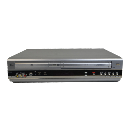
Zenith XBV243 Service Manual
Hide thumbs
Also See for XBV243:
- Service manual (110 pages) ,
- Installation and operating manual (38 pages) ,
- Installation and operating manual (38 pages)
Table of Contents
Advertisement
Quick Links
All manuals and user guides at all-guides.com
SERVICE MANUAL
Product Type:
VCR DVD Combo
Chassis:
D35E Combo
Manual Series: VR168
Manual Part #: 923-03485
Model Line:
E
Product Year:
2002
CONTENTS
General Info ................................................. 1
Service Menu ................................................ 2
Servicing ..................................................... 3
Parts List ..................................................... 4
Diagrams ...................................................... 5
Schematics ................................................... 6
Published March 2002
by Technical Publications
Zenith Electronics Corporation
201 James Record Road
Huntsville, Alabama 35824-1513
Copyright
2002 by Zenith Electronics Corporation
Model Series:
XBV243
Advertisement
Table of Contents
Troubleshooting

Related Manuals for Zenith XBV243


Summary of Contents for Zenith XBV243
- Page 1 Service Menu ..........2 Servicing ............. 3 Parts List ............. 4 Diagrams ............5 Schematics ........... 6 Published March 2002 by Technical Publications Zenith Electronics Corporation 201 James Record Road Huntsville, Alabama 35824-1513 Copyright 2002 by Zenith Electronics Corporation...
- Page 2 When servicing this product, under no circumstances should the original design be modified or altered without permission from Zenith Electronics Corporation. All components should be replaced only with types identical to those in the original circuit and their physical location, wiring and lead dress must conform to original layout upon completion of repairs.
-
Page 3: Table Of Contents
All manuals and user guides at all-guides.com TABLE OF CONTENTS SECTION 6 DIAGRAMS SECTION 1 SUMMARY EXPLODED VIEW ........... 6-1 SPECIFICATIONS .......... 1-1 VCR EXPLODED VIEW ........6-2 KEY TO ABBREVIATIONS ........ 1-2 DVD EXPLODED VIEW ........6-3 SERVICING PRECAUTIONS ......1-3 MAIN BLOCK DIAGRAM ........ - Page 4 All manuals and user guides at all-guides.com - TOC-2 -...
-
Page 5: Section 1 Summary
All manuals and user guides at all-guides.com section 1 SUMMARY SUMMARY SPECIFICATIONS DVD PART Power supply ........AC 120 V, 60 Hz Power ..........23 W Mass ............ 3.0kg(6.6lbs) External dimensions ......430 x 88 x 247 (W x H x D) Signal system ........ -
Page 6: Key To Abbreviations
All manuals and user guides at all-guides.com SUMMARY KEY TO ABBREVIATIONS Alternating Current Maximum Automatic Color Control Modulator Adjust Microphone Audio Erase Minimum Automatic Frequency Control Mixer, Mixing Automatic Fine Tuning Monostable, Multivibrator Automatic Gain Control Mono Multi Vibrator Automatic Level Control Modulation, Modulator Amplitude Modulation MODEM... -
Page 7: Servicing Precautions
All manuals and user guides at all-guides.com SUMMARY SERVICING PRECAUTIONS ELECTROSTATICALLY SENSITIVE (ES) DEVICES Some semiconductor (solid state) devices can be CAUTION: Before servicing the product covered by this damaged easily by static electricity. Such components service data and its supplements and addends, read and commonly are called Electrostatically Sensitive (ES) follow the SAFETY PRECAUTIONS. -
Page 8: Package Contents
All manuals and user guides at all-guides.com SUMMARY PACKAGE CONTENTS CABLE SET ASS'Y RF CABLE PHONO CORD 1WAY PHONO CORD 2WAY BATTERY REMOCON OWNER'S MANUAL PACKING SHEET ACKING PACKING BOX CARTON OPTIONAL PARTS VR168 - 923-03485 D35E COMBO - SUMMARY... -
Page 9: Section 2 Chassis
All manuals and user guides at all-guides.com section 2 CHASSIS CHASSIS CABINET FRONT DISPLAY Angle icon indicator PROGRAM indicator CD REC indicator Repeat playback mode indicators ALL MP3 -R W BIL PR SAP CH Total playing time/elapsed time indicators Stereo indicator Chapter/Track number indicator DVD indicator Title number indicator... -
Page 10: Self Diagnostics
All manuals and user guides at all-guides.com CHASSIS NOTES SELF DIAGNOSTICS 1. Error codes will not be stored. The program must be SELF DIAGNOSTIC OVERVIEW re-initialized as described in the preceding step. Provides service personnel a convenient service aid by a 2. -
Page 11: Cabinet Disassembly
All manuals and user guides at all-guides.com CHASSIS CABINET DISASSEMBLY CAUTION BEFORE SERVICING Electronic parts are susceptible to static electricity and may easily be damaged. Follow proper grounding procedures. Many screws are used inside the unit. To prevent missing, dropping, etc. of the screws, always use a magnetized screw driver in servicing. -
Page 12: Circuit Board Disassembly
All manuals and user guides at all-guides.com CHASSIS CIRCUIT BOARD DISASSEMBLY DIGITRON AND KEY CIRCUIT BOARD Note: Before removing the main circuit board, be sure 1. Remove the front panel. (See Fig. 2-3) to short circuit the laser diode output land. After 2. -
Page 13: Section 3 Electrical
All manuals and user guides at all-guides.com SECTION 3 Electrical ELECTRICAL TROUBLESHOOTING 1. Power(SMPS) CIRCUIT (2) No 12VA (TO CAP, DRUM MOTOR) (1) No 5.3VA (SYS/Hi-Fi/TUNER) NO 5.3VA. NO 12VA. Check or Replace Is the Vcc (13V) supplied to (+) Replace F101. - Page 14 All manuals and user guides at all-guides.com ELECTRICAL TROUBLESHOOTING (CONTINUED) (5) No REG 5V (AVCP) (4) No 5V (TO DVD) NO 5V. No REG 5V. Is 5.3VA present on Is 5.3VA present on 5.3VA Line Check. 5.3VA Line Check. Q113 Emitter? Q117 Collector? Is the Q115 Base Is 33V present on...
- Page 15 All manuals and user guides at all-guides.com ELECTRICAL TROUBLESHOOTING (CONTINUED) -29VA. (9) No 8VA -29VA. NO 8VA. Is Vcc (13V) supplied to Check or Replace Check or Replace (+) terminal in D114? D108. D110. Check or Replace Is Vcc (12V) supplied D114.
- Page 16 All manuals and user guides at all-guides.com ELECTRICAL TROUBLESHOOTING (CONTINUED) 2. SYSTEM/KEY CIRCUIT (1) AUTO STOP Auto Stop Does the SW30 waveform Check the Drum Motor appear at IC501 signal. Pin24? Do T/UP Reel Pulses Do the T-UP Reel Pulses Does 5.2V appear at appear at Q514 appear at IC501 Pin4?
- Page 17 All manuals and user guides at all-guides.com ELECTRICAL TROUBLESHOOTING (CONTINUED) 3. SERVO CIRCUIT (1) Unstable Video in PB MODE Unstable Video in PB Mode. Does the Noise level of the screen change periodically? Do the CTL pulses appear Is the adjustment height of at IC501 Pin37? the CTL Head accurate? Does the CFG waveform...
- Page 18 All manuals and user guides at all-guides.com ELECTRICAL TROUBLESHOOTING (CONTINUED) (3) When the Capstan Motor doesn’t run When the Capstan Motor doesn’t run, Refer to “SMPS (CAPSTAN/12Volt) Does 12VA appear at PMC01? Trouble Shooting”. Does 2.8V appear at PMC01? Check PMC01 and the Capstan Does the PWM signal appear at IC501 Pin25? Motor Ass’y.
- Page 19 All manuals and user guides at all-guides.com ELECTRICAL TROUBLESHOOTING (CONTINUED) KEY doesn't work. KEY doesn’t work. Is 5V applied to Refer to “SMPS 5.3VA Trouble Shooting”. IC501 Pin 15? Does LED or FLD change Replace the defective when a function button is switches.
-
Page 20: Dvd Troubleshooting
All manuals and user guides at all-guides.com ELECTRICAL DVD TROUBLESHOOTING (CONTINUED) 5. Y/C CIRCUIT (1) No Video in EE Mode No Video in EE Mode Does the Video signal Check DVD Video Input (IC802, Pin29), Tuner Video Input appear at IC301 (TU701 Pin24), Line Video Input (JK801), respectively. - Page 21 All manuals and user guides at all-guides.com ELECTRICAL DVD TROUBLESHOOTING (CONTINUED) (2) When the Y(Luminance) signal doesn’t appear on the screen in PB Mode Is 5V applied to IC301 Check the line of the REG Pins 12, 36, 61, 67, 90, 96? 5V Line.
- Page 22 All manuals and user guides at all-guides.com ELECTRICAL TROUBLESHOOTING (CONTINUED) Y/C CIRCUIT (3) When the C(Color) signal doesn’t appear on the screen in PB Mode, Is 5V applied to IC301 Check the line of the REG Pins 12, 36, 61, 67, 90, 96? 5V Line.
- Page 23 All manuals and user guides at all-guides.com ELECTRICAL TROUBLESHOOTING (CONTINUED) (4) When the Video signal doesn’t appear on the screen in REC Mode, REC mode Check the EE mode Is EE mode normal? Is color? Is brightness ? Is color? Is the brightness signal Does signal appear at IC301 Pins 58, 60?
- Page 24 All manuals and user guides at all-guides.com ELECTRICAL TROUBLESHOOTING (CONTINUED) 6. Hi-Fi CIRCUIT (A) No Sound(EE Mode) No Sound. Check the TU Audio of IC801 Check IC751 Pins 30, 31. Pins 1, 3 Check the DVD Audio of IC801 Check the DVD MODULE. Pins 4, 5.
- Page 25 All manuals and user guides at all-guides.com ELECTRICAL TROUBLESHOOTING (CONTINUED) 3. Y/C CIRCUIT (B) Hi-Fi Playback PB mode No Sound. Check the Vcc of IC801 Check Power. (Pins 34, 40) Check the Hi-Fi Selection switch. Check IC501 Pin23 (IC801 Pin 41) and the Tape quality. (A.H/SW) Is the RF Envelope at IC801 Pin 44 over 2Vp-p?
- Page 26 All manuals and user guides at all-guides.com ELECTRICAL TROUBLESHOOTING (CONTINUED) ( C ) Hi-Fi REC. It is impossible to record Hi-Fi Audio signal. Check Vcc of IC801.(Pins34, 40) Check Power. Check IC801 Pin42(Data), Pin43(CLOCK). Check ports of µ-CPM. Check Audio input signal of IC801 Do Audio signals appear at IC801 Pins2, 3(TU.A.), 4, 5(DVD.A.), Pins16, 17?
- Page 27 All manuals and user guides at all-guides.com ELECTRICAL TROUBLESHOOTING (CONTINUED) 7. Tuner/IF CIRCUIT (A) No Picture on the TV screen No picture on the TV screen Is the Video signal at Is +33V applied to TU701 Check 33V line. the TU701 Pin 24. Pin16? Is +5V applied to TU701 Check 5V line.
- Page 28 All manuals and user guides at all-guides.com ELECTRICAL TROUBLESHOOTING (CONTINUED) (B) No Sound No Sound. Check the Vcc of IC751 Pins1, Check 5.2V Line. 11, 19, 22, 33. Check the Tuner SiF signal at Check the Tuner SIF of TU701 Pin22. IC751Pin2.
- Page 29 All manuals and user guides at all-guides.com ELECTRICAL TROUBLESHOOTING 1. µ-COM Circuit B. Video abnormal A. Audio abnormal AUDIO ABNORMAL VIDEO ABNORMAL Check Video jack. Check Audio jack. YES(If OK) YES(If OK) Check MPEG_CLK Signal Refer to Video part. of MPEG part. YES(If OK) YES(If OK) Refer to Audio part.
- Page 30 All manuals and user guides at all-guides.com ELECTRICAL DVD TROUBLESHOOTING (CONTINUED) D. Picture abnormal PICTURE ABNORMAL Check the disc. Refer to Servo part If OK Check MPEG_CLK Signal of MPEG part YES(If OK) Check DSP YES(If OK) Check MPEG YES(If OK) Replace B/D E.
- Page 31 All manuals and user guides at all-guides.com ELECTRICAL TROUBLESHOOTING (CONTINUED) 2. MPEG Circuit Power is on Check power & clock. Does Logo appear Check power & clock. on the screen? Does the Is MPEG data moving picture of the DVD Disc Check CD/DVD DSP signal normal? play on the screen...
- Page 32 All manuals and user guides at all-guides.com ELECTRICAL TROUBLESHOOTING (CONTINUED) 3. RF/Servo Circuit CHECK POINT(General) Does signal go "High" to IC201 Pin194 when power is on? Does signal pulse Check "2.µ-COM Part". input to IC201 Pins 58, 59 when power is on? Does Does Replace X301 or IC304...
- Page 33 All manuals and user guides at all-guides.com ELECTRICAL TROUBLESHOOTING (CONTINUED) No disc No disc Power on Check loading Part. Push Pick-up to inner Does tray open or close? track to the end by hand. Does PMD03 Pin 13 DECK assembly is change high to low? defective.
- Page 34 All manuals and user guides at all-guides.com ELECTRICAL TROUBLESHOOTING (CONTINUED) DISC IN DISC IN OPEN/CLOSE Fig.3. FOCUS ERROR waveform Check the focus error Check IC2A1 Pin 11,12,13,14 FOCUS ON? movingthe lens up and in DVD Mode down. (IC2A1 Pin 42) IC201 no output : Pick-up is defective.
- Page 35 All manuals and user guides at all-guides.com ELECTRICAL TROUBLESHOOTING (CONTINUED) CHECK A Check RF Eye-Pattern. Check IC2A1 Pins 5, 6, 7, 8. No signal: Pick-up is defective RF : 1.5-1.6V(IC2A1 Pin 57) Does the Is the eye-pattern vivid? sawtooth waveform emit Does the 1.6V emit? Replace IC2A1.
- Page 36 All manuals and user guides at all-guides.com - 3-24 -...
-
Page 37: Section 4 Mechanical
All manuals and user guides at all-guides.com SECTION 4 Mechanical MECHANISM - VCR VCR DECK MECHANISM PART LOCATIONS Top View Bottom View T: Top, B:Bot NOTES: • When reassembling, perform the procedure in the reverse order. • When reassembling, confirm Mechanism and Mode Switch Alignment Position (refer to Page 4-14) VR168 - 923-03485 D35E COMBO - SERVICING... - Page 38 All manuals and user guides at all-guides.com MECHANISM - VCR DRUM ASSEMBLY Fig. B-1 1) Unplug the Drum FPC Connector. 2) Remove three Screws (S1) on the bottom side and separate the Drum assembly. Cap FPC 3) Unhook (H1), (H2) and separate the Holder FPC and Cap FPC.
- Page 39 All manuals and user guides at all-guides.com MECHANISM - VCR PLATE TOP (FIG. A-2-1) 1)To Remove, use a screwdriver to carefully free the tabs at each end (B and B’ in the figure at right). Rotate the plate upwards to free the slotted hooks (C') from the studs (C and C’...
- Page 40 All manuals and user guides at all-guides.com MECHANISM - VCR HOLDER ASSEMBLY CST (FIG. A-2-2) 1) Move the Holder assembly CST in direction of arrow Gear Rack F/L and lift the left side through slot (D) . 2) Pull the right side of the Holder assembly CST from the guided holes in the Chassis.
- Page 41 All manuals and user guides at all-guides.com MECHANISM - VCR ARM ASSEMBLY CLEANER (FIG. A-3-1) BASE ASSEMBLY A/C HEAD (FIG. A-3-3) 1) Carefully pry tab “A” (see Fig. A-3-1) to clear the 1) Remove Screw (S4) and lift the Base assembly A/C embossed tab on the chassis.
- Page 42 All manuals and user guides at all-guides.com MECHANISM - VCR Arm Assembly Tension (Fig. A-4-3) (H11) Spring TB Brake Assembly T (Fig. A-4-1) Spring Tension Reel S (Fig. A-4-4) Reel T (Fig. A-4-4) Spring RS Brake Assembly RS (Fig. A-4-2) (H12) (H9) (H10)
- Page 43 All manuals and user guides at all-guides.com MECHANISM - VCR Opener Lid (Fig. A-5-2) Assembly Pinch (Fig. A-5-3) Base Assembly P4 Lever T/up (H13) (Fig. A-5-1) (Fig. A-5-4) (H13) Arm T/up (Fig. A-5-5) Chassis Fig. A-5 LEVER T/UP (FIG. A-5-4) BASE ASSEMBLY P4 (FIG.
- Page 44 All manuals and user guides at all-guides.com MECHANISM - VCR CLUTCH ASSEMBLY D35 (FIG. A-6-4) BELT & MOTOR CAPSTAN (FIG. A-6-1/2) Remove Washer (W1) and lift the Clutch assembly 1) Remove the Belt Capstan. D35. 2) Remove the three Screws (S5) from the bottom of the Chassis and lift the Motor Capstan.
- Page 45 All manuals and user guides at all-guides.com MECHANISM - VCR GEAR DRIVE & CAM (FIG. A-7-1/2) PLATE SLIDER (FIG. A-7-4) 1) Remove Washer (W2) and lift the Gear Drive. Lift the Plate Slider. 2) Unhook Hook (H14) of the Gear Cam and lift the LEVER TENSION (FIG.
- Page 46 All manuals and user guides at all-guides.com MECHANISM - VCR 2) Move Base assembly P3 in the direction of the arrow GEAR ASSEMBLY P2/P3 (FIG. A-8-1/2) (B) along the slot in the Chassis and disassemble it 1) Lift the Gear assembly P2. from the bottom side.
- Page 47 All manuals and user guides at all-guides.com MECHANISM - VCR BASE LOADING (FIG. A-9-1) ARM ASSEMBLY IDLER (FIG. A-9-3) 1) Remove the Screw (S7). Pinch (B) and (C) as shown in Fig. A-9-3, and lift. 2) Lift the Base Loading. NOTE: When disassembling, be careful not to catch part BASE TENSION (FIG.
- Page 48 All manuals and user guides at all-guides.com MECHANISM - VCR TOOLS NEEDED FOR SERVICE 1. Cassette Torque meter 2. Alignment tape 3. Torque gauge SRK-VHT-303(Not SVC part) 600g.Cm ATG 4. Torque gauge adaptor 5. Post height adjusting driver 6. + Type driver 4-12 VR168 - 923-03485 D35E COMBO - SERVICING...
-
Page 49: Vcr Alignment
All manuals and user guides at all-guides.com MECHANISM - VCR VCR ALIGNMENT ALIGNMENT POSITION CHECK Mechanism Alignment Position Check Purpose: To determine if the Mechanism is in the correct Position when a Tape is ejected. Test Conditions (Mechanism Test Equipment/ Fixture Check Point Condition) Blank tape... - Page 50 All manuals and user guides at all-guides.com MECHANISM - VCR PREPARATION FOR ADJUSTMENT (To set the Deck Mechanism to the Loading state with- Cover the Holes of the End Sensors at both sides of out inserting a Cassette Tape). the Bracket Side (L) and Bracket Assembly Door to prevent a light leak.
- Page 51 All manuals and user guides at all-guides.com MECHANISM - VCR GUIDE ROLLER HEIGHT ADJUSTMENT Purpose: To regulate the Height of the Tape so that the Bottom of the Tape runs along the Tape Guide Line on the Lower Drum. PRELIMINARY ADJUSTMENT Test Equipment/ Fixture Adjustment Point Post Height Adjusting Driver...
- Page 52 All manuals and user guides at all-guides.com MECHANISM - VCR AUDIO/CONTROL (A/C) HEAD ADJUSTMENT Purpose: To insure that the Tape passes accurately over the Audio and Control Tracks in exact Alignment in both the Record and Playback Modes. PRELIMINARY ADJUSTMENT (Height and Tilt Adjustment) Perform the Preliminary Adjustment when there is no Audio Output Signal with the Alignment Tape.
- Page 53 All manuals and user guides at all-guides.com MECHANISM - VCR 3) If Folding or Curling is observed at the Top of it, CONFIRM OPERATION slowly turn the Tilt Adjustment Screw (C) counter- Confirm that the Tape passes smoothly between the clockwise.
- Page 54 All manuals and user guides at all-guides.com MECHANISM - VCR ADJUSTMENT AFTER REPLACING DRUM ASSEMBLY (VIDEO HEADS) Purpose: To Test Conditions Test Equipment/ Fixture Connection Point Adjustment Points (Mechanism Condition) CH-1: PB RF Envelope Guide Roller Precise Oscilloscope Play the blank tape CH-2: NTSC: SW 30Hz Adjustment Alignment tapes...
-
Page 55: Maintenance/Inspection Procedure
All manuals and user guides at all-guides.com MECHANISM - VCR MAINTENANCE/INSPECTION PROCEDURE CHECK BEFORE STARTING REPAIRS The following faults can be remedied by cleaning and oiling. Check the needed lubrication and the conditions of cleanliness in the unit. Check with the customer to find out how often the unit is used, and then determine that the unit is ready for inspection and maintenance. - Page 56 All manuals and user guides at all-guides.com MECHANISM - VCR REQUIRED MAINTENANCE SUPPLIES REQUIRED FOR INSPECTION AND MAINTENCE The recording density of a VCR(VCP) is much higher than (1) Grease: Kanto G-311G (Blue) or equivalent that of an audio tape recorder. VCR(VCP) components (2) Isopropyl Alcohol or equivalent must be very precise, at tolerances of 1/1000mm, to (3) Cleaning Patches...
- Page 57 All manuals and user guides at all-guides.com MECHANISM - VCR GREASING 1) Greasing guidelines. Apply grease, with a cleaning patch. Do not use excessive grease as it may come into contact with the tape transport or drive sys- tem. Wipe any excess and clean with a cleaning patch wetted in Isopropyl Alcohol.
- Page 58 All manuals and user guides at all-guides.com MECHANISM - VCR GEAR , F/R GEAR AY, P2 & P3 4-22 VR168 - 923-03485 D35E COMBO - SERVICING...
-
Page 59: Vcr Mechanism Troubleshooting
All manuals and user guides at all-guides.com MECHANISM - VCR VCR MECHANISM TROUBLESHOOTING 1.Deck Mechanism Auto REW doesn't work. Is the output of END sensor of supply side "H": more than 3.5V? Or, less than 0.7V~1V? Is the Vcc voltage of Check the syscon power. - Page 60 All manuals and user guides at all-guides.com MECHANISM - VCR AUTO STOP. (PLAY/CUE/REV) In Play/Cue/Rev is the pinch roller in contact with the Replace Drum Motor. capstan shaft. Are there T/up and Check Servo, Syscon. supply reel pulses. Check the Syscon, µ-COM. Replace Reel Sensor.
- Page 61 All manuals and user guides at all-guides.com MECHANISM - VCR In PB mode Tape Presence not sensed. Is the Pinch Roller attached Check Alignment positions to the Capstan Motor Shaft? (page 4-14) Does the T/Up Is the Belt ok? Replace the Belt. Reel turn? Check the clutch and Does the Capstan Motor turn?
- Page 62 All manuals and user guides at all-guides.com MECHANISM - VCR 2. Front Loading Mechanism Cassette cannot be inserted. Does the Lever Assembly Is the Lever Assembly Switch Replace or add the Lever Switch work? Spring damaged or omitted? Assembly Switch Spring. Does the CST IN Switch work Replace CST IN Switch.
- Page 63 All manuals and user guides at all-guides.com MECHANISM - VCR Cassette will not load. Does the CST insert? Does the opener Lid work? Replace the Opener Lid. Does the Gear Rack F/L work? Does the Opener Door work? Replace the Rear Rack F/L. Does the Arm Assembly F/L work? Is the opener Door assembled correctly? Does the L/D Motor work?
-
Page 64: Dvd Deck Mechanism
All manuals and user guides at all-guides.com MECHANISM - DVD DVD DECK MECHANISM TOP VIEW (WITHOUT TRAY) 2 Screws, 2 Locking Tabs 4 Screws, 1 Connector 1 Locking Tabs BOTTOM VIEW 1 Screw 1 Screw 1 Locking Tab 1 Locking Tab 1 Locking Tab 1 Hook 2Screw... -
Page 65: Mechanism Disassembly
All manuals and user guides at all-guides.com MECHANISM - DVD TRAY DISC (FIG. 4-2) MECHANISM DISASSEMBLY 1) Insert and push a Driver in the emergency eject hole HOLDER CLAMP (FIG. 4-1) (A) at the right side, or put the Driver on the Lever 1) Release 1 Screws (S1). - Page 66 All manuals and user guides at all-guides.com MECHANISM - DVD BASE ASSEMBLY SLED (FIG. 4-3) 1) Release 4 Screws (S2). 2) Disconnect the FFC Connector (C1) GEAR ASSEMBLY FEED Unhook the Locking Tab (L2) in the direction of the arrow. GEAR MIDDLE GEAR ASSEMBLY RACK Release the Scerw (S3)
- Page 67 All manuals and user guides at all-guides.com MECHANISM - DVD FRAME ASSEMBLY UP/DOWN Base Main. Note: Put the Base Main face down (Bottom Side) GEAR LOADING (FIG. 4-4) 1) Release the Screw (S4) GUIDE UP/DOWN (FIG. 4-4) 2) Unlock the Locking Tab (L3) in the direction of the 1) Move the Guide Up/Down in direction of arrow (A) as arrow and then lift up the Frame Assembly Up/Down to in Fig.(A)
-
Page 68: Deck Mechanism Adjustment
All manuals and user guides at all-guides.com MECHANISM - DVD Fig.11. Adjusting Screen Display DECK MECHANISM ADJUSTMENT 1) Insert Disc (Only Open/Close Key Pressing) 2) Wait Until the Sector Display is about 200,000 (Fig.11) 3) Adjust R-Skew adjusting Point until the Error rate has minimum rate with L-wrench (3mm). -
Page 69: Component Parts
The following information is for models in and out of C238 0CH1104K942 Cap, Fixed Ceramic, 0.1Uf 50V 80%,-20% C239 0CH1104K942 Cap, Fixed Ceramic, 0.1Uf 50V 80%,-20% warranty. The XBV243 model is component level repair. C240 0CH1222K562 Cap, Fixed Ceramic, 2200Pf 50V 10% To Order Parts: call 1-888-3-ZENITH C241 0CH1104K942 Cap, Fixed Ceramic, 0.1Uf 50V 80%,-20%... - Page 70 All manuals and user guides at all-guides.com COMPONENT PARTS LIST XBV243 NOTE: This list will enable you to easily determine the parts used on each Model, Chassis, or Assembly. PART# DESCRIPTION PART# DESCRIPTION C2C6 0CH1472K562 Cap, Fixed Ceramic, 4700Pf 50V 10%...
- Page 71 All manuals and user guides at all-guides.com COMPONENT PARTS LIST XBV243 NOTE: This list will enable you to easily determine the parts used on each Model, Chassis, or Assembly. PART# DESCRIPTION PART# DESCRIPTION C504 0CH1104K942 Cap, Fixed Ceramic, 0.1Uf 50V 80%,-20%...
- Page 72 All manuals and user guides at all-guides.com COMPONENT PARTS LIST XBV243 NOTE: This list will enable you to easily determine the parts used on each Model, Chassis, or Assembly. PART# DESCRIPTION PART# DESCRIPTION Q2M1 0TR124009AP Transistor, Bipolars, Dtc124Ek Tp Rohm Korea 3K/R...
- Page 73 All manuals and user guides at all-guides.com COMPONENT PARTS LIST XBV243 NOTE: This list will enable you to easily determine the parts used on each Model, Chassis, or Assembly. PART# DESCRIPTION PART# DESCRIPTION R301 0RH1002C622 Resistor, Metal (Chip) 10K Ohm 1/16W 5%...
- Page 74 All manuals and user guides at all-guides.com COMPONENT PARTS LIST XBV243 NOTE: This list will enable you to easily determine the parts used on each Model, Chassis, or Assembly. PART# DESCRIPTION PART# DESCRIPTION R599 0RH0000C622 Resistor, Metal (Chip) 0 Ohm 1/16W 5%...
- Page 75 All manuals and user guides at all-guides.com COMPONENT PARTS LIST XBV243 NOTE: This list will enable you to easily determine the parts used on each Model, Chassis, or Assembly. PART# DESCRIPTION PART# DESCRIPTION 4680R-B005A Motor (Mech) Drum I2Oal05 Sejin-S C127...
- Page 76 All manuals and user guides at all-guides.com COMPONENT PARTS LIST XBV243 NOTE: This list will enable you to easily determine the parts used on each Model, Chassis, or Assembly. PART# DESCRIPTION PART# DESCRIPTION C346 0CC0500K015 Cap, Fixed Ceramic, 5Pf 50V...
- Page 77 All manuals and user guides at all-guides.com COMPONENT PARTS LIST XBV243 NOTE: This list will enable you to easily determine the parts used on each Model, Chassis, or Assembly. PART# DESCRIPTION PART# DESCRIPTION C814 0CE4764F638 Cap, Fixed Electro, 47Uf 16V 20%...
- Page 78 All manuals and user guides at all-guides.com COMPONENT PARTS LIST XBV243 NOTE: This list will enable you to easily determine the parts used on each Model, Chassis, or Assembly. PART# DESCRIPTION PART# DESCRIPTION Q515 0TR103009AE Transistor, Bipolars, Krc103M Tp Kec (Krc1203)
- Page 79 All manuals and user guides at all-guides.com COMPONENT PARTS LIST XBV243 NOTE: This list will enable you to easily determine the parts used on each Model, Chassis, or Assembly. PART# DESCRIPTION PART# DESCRIPTION R543 0RD1000F608 Resistor, Carbon Film, 100 Ohm 1/6W 5%...
- Page 80 All manuals and user guides at all-guides.com...
-
Page 81: Section 6 Diagrams
All manuals and user guides at all-guides.com SECTION 6 Diagrams XBV243 Exploded View VR168 - 923-03485 D35E COMBO - DIAGRAMS... -
Page 82: Vcr Exploded View
All manuals and user guides at all-guides.com XBV243 VCR Exploded View 002A 054A VR168 - 923-03485 D35E COMBO - DIAGRAMS... -
Page 83: Dvd Exploded View
All manuals and user guides at all-guides.com XBV243 DVD Exploded View VR168 - 923-03485 D35E COMBO - DIAGRAMS... -
Page 84: Main Block Diagram
All manuals and user guides at all-guides.com XBV243 Main Block Diagram DISC DVD_LDQM,DVD_SD,CSI IC302 MIRR,TZC DVD_MA[0:11] IC205 GM72V1621 DRAM 1M x 16bit IC2A1 GM7IC4260CJ SDRAM DVD_MD[0:15] 256K x 16bit FE,TE,RFRP,SBADD,DVD/CD RF 33P3721 CD,DVD:A,B,C,D,E,F RF Signal PICK SPINDLE Processor TEBAL,FEBAL, MO TOR... -
Page 85: Power Block Diagram
All manuals and user guides at all-guides.com XBV243 Power Block Diagram R101 SNUBBER TO SYS RECTIFIER & BD101 FD(+) BLOCK S/W BLOCK F102 SMOOTHING (Q110, Q111, (D101, R104, FROM -COM (D107, C121, ZD101) R151, R152) C105, C106) STAND BY 'H'... -
Page 86: Tuner-If Block Diagram
All manuals and user guides at all-guides.com XBV243 Tuner-IF Block Diagram CH/SW VCR/TV IC751 MSP3407 VR168 - 923-03485 D35E COMBO - DIAGRAMS... -
Page 87: Y/C Block Diagram
All manuals and user guides at all-guides.com XBV243 Y/C Block Diagram (PB Mode) S y s t e m V . H / S W 3 0 ( F R O M u - C O M ) C-CCD X-tal Serial Cont V . -
Page 88: Audio Block Diagram
All manuals and user guides at all-guides.com XBV243 Audio Block Diagram (EE Mode) (REC Mode) TUNER IC750 IC801 IC301 TU701 MSP3407 TDA9605H HA118717F NORMAL AUDIO OUT R AUDIO COMP OUT L LINE AUDIO(R) IN REAR Jack LINE AUDIO(L) IN A. OUT (L) A. -
Page 89: Hifi Block Diagram
All manuals and user guides at all-guides.com XBV243 Hifi Block Diagram VIDEO INPUT BLOCK Hi-Fi/ AUDIO INPUT 36 35 BLOCK Tu A.IN 'L' 28 29 Tu A.IN 'R' A.OUT 'L' A.OUT DVD A.IN 'L' IC802 To JACK IC801 A.OUT 'R' DVD A.IN 'R'... - Page 90 All manuals and user guides at all-guides.com XBV243 System Block Diagram I - LIMIT TO/ FROM DECK TO/ FROM AVCP 5.3VA MODE S/W MS501 32 38 MODE S1 C. SYNC MODE S2 MODE S3 OSD 'H' REC 'H' MODE S4...
-
Page 91: Section 7 Schematics
All manuals and user guides at all-guides.com Power Supply Circuit SECTION 7 schematics No power. BD101, R101 are defective. Digitron Error. D107, D108, ZD101 are defective. 12VA no power. D110 is defective. 2.5V, 3.3V no power. D111 is defective. Switching Error. IC101 is defective. -
Page 92: Tuner/If Circuit
All manuals and user guides at all-guides.com Tuner/IF Circuit Tuner doesnÕt operate. µ-COM is defective. CH memory doesnÕt operate. 33V Power is defective. IC751 doesnÕt operate. X751 is defective. 3/4 CH switching is impossible. µ-COM is defective. VIDEO OUT AUDIO OUT CRITICAL SAFETY COMPONENTS ARE IDENTIFIED BY THE SYMBOL ALL SYMBOLS WITH “M”... -
Page 93: Av Circuit
All manuals and user guides at all-guides.com AV Circuit Video output Noise in REC/PB. No Color in REC/PB. No Color in playout. Video output Level is unstable. No Color in PB. Video H/SW level is defective. R333, C350, C349 are defective. L306, C346 are defective. -
Page 94: Hifi Circuit
All manuals and user guides at all-guides.com Hifi Circuit IC801 Pins42, 43 aredefective. All Audio is not appear. 44 Pin is defective. Hi-Fi Audio is not appear. CRITICAL SAFETY COMPONENTS ARE IDENTIFIED BY THE SYMBOL ALL SYMBOLS WITH “M” ON END OF DESIGNATOR D35E COMBO - SHEET 4 VR168 - 923-03485 AND/OR SHADING. -
Page 95: System Circuit
All manuals and user guides at all-guides.com System Circuit MS501 is defective. Deck is abnormal. SW is defective. Alarm operate. Key service dead. TUNER Tuning error. Capstan Motor will not operate. X501 is defective. µ-CON will not operate. IC601 Digitron is defective. LED &... -
Page 96: Dvd Circuit
All manuals and user guides at all-guides.com DVD Circuit IC203 is defective. AD Converter Error - No tracking/Focus control IC204 is defective. Scratched CD Audio abnormal. TRACKING LOOP SLED LOOP WAVEFORM FOCUS LOOP SPINDLE LOOP CRITICAL SAFETY COMPONENTS ARE IDENTIFIED BY THE SYMBOL ALL SYMBOLS WITH “M”... -
Page 97: Drive Rf Circuit
All manuals and user guides at all-guides.com Drive RF Circuit Q2A1, Q2A2 are defective. CD/DVD LD will not be on. IC2A2 is defective. No fucus & tracking control. TRACKING LOOP SLED LOOP WAVEFORM FOCUS LOOP SPINDLE LOOP CRITICAL SAFETY COMPONENTS ARE IDENTIFIED BY THE SYMBOL ALL SYMBOLS WITH “M”... -
Page 98: Mpeg Circuit
All manuals and user guides at all-guides.com MPEG Circuit ¥ NO 2CH AUDIO OUT ¥ NO 2CH AUDIO OUT ¥ NO VCD SCREEN DISPLAY. ¥ NO CD SOUND OUT. ¥ NO DVD SCREEN DISPLAY IC302, IC303 are defective. A/V out bad. W AVEFORM CRITICAL SAFETY COMPONENTS ARE IDENTIFIED BY THE SYMBOL ALL SYMBOLS WITH “M”... -
Page 99: Audio Circuit
All manuals and user guides at all-guides.com Audio Circuit 2CH L SIGNAL 2CH R SIGNAL CRITICAL SAFETY COMPONENTS ARE IDENTIFIED BY THE SYMBOL ALL SYMBOLS WITH “M” ON END OF DESIGNATOR VR168 - 923-03485 D35E COMBO - SHEET 9 AND/OR SHADING. REPLACE ONLY WITH PART NUMBERS SPECIFIED. INDICATE SURFACE MOUNTED COMPONENT... -
Page 100: Micro Circuit
All manuals and user guides at all-guides.com Micro Circuit Servo will not operate FLASH ROM DRAM FLD Error MAIN CPU Video output level is unstable CPLD Open, Close Error EEPROM Servo will not operate X501 No Power on CRITICAL SAFETY COMPONENTS ARE IDENTIFIED BY THE SYMBOL ALL SYMBOLS WITH “M”... -
Page 101: Jackpack Circuit
All manuals and user guides at all-guides.com Jackpack Circuit S VIDEO (C) COM P.VIDEO AUDIO (L) S VIDEO (Y) CRITICAL SAFETY COMPONENTS ARE IDENTIFIED BY THE SYMBOL ALL SYMBOLS WITH “M” ON END OF DESIGNATOR VR168 - 923-03485 7-11 D35E COMBO - SHEET 11 AND/OR SHADING. -
Page 102: Vcr Pcb Layout
All manuals and user guides at all-guides.com VCR PCB Layout LOCATION GUIDE CRITICAL SAFETY COMPONENTS ARE IDENTIFIED BY THE SYMBOL ALL SYMBOLS WITH “M” ON END OF DESIGNATOR D35E COMBO - SHEET 12 VR168 - 923-03485 7-12 AND/OR SHADING. REPLACE ONLY WITH PART NUMBERS SPECIFIED. INDICATE SURFACE MOUNTED COMPONENT... -
Page 103: Dvd Pcb Layout Top
All manuals and user guides at all-guides.com DVD PCB Layout Top LOCATION GUIDE CRITICAL SAFETY COMPONENTS ARE IDENTIFIED BY THE SYMBOL ALL SYMBOLS WITH “M” ON END OF DESIGNATOR VR168 - 923-03485 7-13 D35E COMBO - SHEET 13 AND/OR SHADING. REPLACE ONLY WITH PART NUMBERS SPECIFIED. INDICATE SURFACE MOUNTED COMPONENT... -
Page 104: Dvd Pcb Layout Bottom
All manuals and user guides at all-guides.com DVD PCB Layout Bottom LOCATION GUIDE CRITICAL SAFETY COMPONENTS ARE IDENTIFIED BY THE SYMBOL ALL SYMBOLS WITH “M” ON END OF DESIGNATOR D35E COMBO - SHEET 14 VR168 - 923-03485 7-14 AND/OR SHADING. REPLACE ONLY WITH PART NUMBERS SPECIFIED. INDICATE SURFACE MOUNTED COMPONENT... -
Page 105: Other Pcb Layouts
All manuals and user guides at all-guides.com Other PCB Layouts 2. KEY P.C.BOARD 3. CLOCK P.C.BOARD CRITICAL SAFETY COMPONENTS ARE IDENTIFIED BY THE SYMBOL ALL SYMBOLS WITH “M” ON END OF DESIGNATOR VR168 - 923-03485 7-15 D35E COMBO - SHEET 15 AND/OR SHADING. -
Page 106: Waveforms 1/2
All manuals and user guides at all-guides.com Waveforms 1/2 * IC301 Oscilloscope Waveform * IC501 Oscilloscope Waveform IC301 Pin IC301 Pin IC301 Pins 18, 21, IC301 Pin IC501 Pin IC501 Pin IC501 Pin IC501 Pin IC501 Pin 100mV/10msec DIV 100mV/10msec DIV 100mV/10msec DIV 200mV/10msec DIV REC/PB... - Page 107 All manuals and user guides at all-guides.com Waveforms 2/2 IC2A1 Pin 42, Focus Error IC2A1 Pin 41 IC2A1 Pin 41 IC301 Pin 133, Composite IC301 Pin 151, Chrominance IC301 Pin 145, Luminance IC2A1 Pin 36, Pi Tracking Error VBR TRACKING Error (Super video out Mode) (Super video out Mode) IC2A1 Pin 57,...
- Page 108 All manuals and user guides at all-guides.com...
- Page 109 All manuals and user guides at all-guides.com...
- Page 110 All manuals and user guides at all-guides.com...