
Related Manuals for MASSEY FERGUSON RB 4160 V


Summary of Contents for MASSEY FERGUSON RB 4160 V
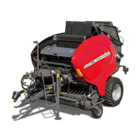
- Page 1 Workshop Service Manual Variable Chamber Baler RB 4160 V RB 4160 V Xtra RB 4180 V RB 4180 V Xtra September 2019 Wolfenbüttel 1764-MF-EN01-SM NA AGCO GmbH - Gebrüder-Welger-Straße 3 - D-38304 72659047 Wolfenbüttel English © AGCO 2019...
- Page 2 CALIFORNIA Proposition 65 Warning WARNING: Diesel engine exhaust and some of its constituents are known to the State of California to cause cancer, birth defects, or other reproductive harm. WARNING: Battery posts, terminals and related accessories contain lead and lead compounds, chemicals known to the State of California to cause cancer, birth defects, or other reproductive harm.
- Page 3 TABLE OF CONTENT General Machine Components Schematics and fault trees Index Find manuals at https://best-manuals.com...
-
Page 4: Table Of Contents
Table of contents 1 General Safety ..............1-3 1.1.1 Safety Icons . - Page 5 Table of contents 1.8.1 Software error codes ..........1-24 Description .
-
Page 6: Safety
1. General 1.1 Safety GUID-71DF61FB-26B8-4A85-A812-3AD956B65B93 [V1] 1.1.1 Safety Icons NOTE: The use of the signal words DANGER, WARNING and CAUTION with the safety messages. The signal word for each message will use the structure that follows: DANGER: Danger Shows data on a possible hazard that if you do not prevent death or injury will occur. WARNING: Warning Shows data on a possible hazard that if you do not prevent death or injury will occur, these will include hazards that occur when guards are not in position. -
Page 7: Safe Driving
1. General • Always keep a minimum distance of 3 m (10 ft) between the machine and electrical power lines, make sure that you monitor the height of the machine when the tailgate is in the open position • Know that the height of the machine is up to 3.50 m (11.5 ft) and with an opened tailgate 4.28 m (14.04 ft), depending on specifications and installed tyres •... -
Page 8: Safe Maintenance
1. General • If necessary by local law install the rear marking plate for Slow Moving Vehicles (SMV) on to the machine • If necessary by local law install the licence plate on the machine • If necessary by local law, install the safety chains. Connect them to a rigid part of the tractor •... -
Page 9: Fire Prevention
1. General • Make sure that there are no people or animals in the danger zone during operation see chapter 1.5 Danger Zones, page 1-18 . This is important in or near areas that are open to bystanders • Keep a minimum distance of 3 m (10 ft) from electrical high-voltage lines when you open the tailgate. The height of the machine is up to 3.50 m (11.5 ft) and with an opened tailgate 4.28 m (14.04 ft), depending on specifications and installed tyres.) •... -
Page 10: Safety Decals
1. General GUID-86BB0F85-F30C-4A7F-8224-E5478BE443AF [V1] 1.2 Safety decals Location and explanation of the safety decals Installation of safety decals 1. Make sure that the installation surface is clean and dry. 2. Make sure that the temperature of the installation surface is not less than 5 °C (41 °F). 3. -
Page 11: Safe Maintenance
1. General 1.3 Safe Maintenance GUID-533CF40B-AAAC-4AD6-9238-49E68C8ADB7F [V1] 1.3.1 Personal protective equipment DANGER: Risk of injury Put on the correct personal protective equipment (PPE). Stop the engine and remove the ignition key. Make sure that the machine stops fully before you make an adjustment or do work on the machine. -
Page 12: Prepare For Emergencies
1. General Mandatory safety signs GUID-D31F8EE2-77EA-4830-B294-9D686FB1849F-high.jpg [High] Fig. 1 Goggles Clothing Gloves Breathing protection Safety boots Ear protection GUID-951A0555-D3B6-4A9A-A2F5-248B1EFA86CE [V1] 1.3.2 Prepare for emergencies Make sure that first aid equipment is available. Make sure that other persons know you are at work on the machine. Make sure that you can speak to the emergency services if necessary. -
Page 13: Correct Maintenance
1. General Always: • Use an applicable container when you remove fluids. • Do not use food or drink containers. • Do not put dangerous waste in the ground, down a drain or into a water source. GUID-3CF76504-0D55-40A8-AE19-E3121BA4E123 [V1] 1.3.4 Correct maintenance •... -
Page 14: To Move The Machine Without Brakes
1. General Apply the manually operated brake (1). GUID-EAD6F6E5-A533-4F55-91A0-24618026E76D-high.jpg [High] Fig. 2 Put the wheel chocks in position. Install the support foot. For a hydraulic brake system: a) Disconnect the hydraulic brake hose from the tractor and immediately connect it to the dummy coupling on the platform. -
Page 15: Take The Machine Out Of Operation
1. General Before starting the procedure When the tractor air hoses are not connected and the air reservoir is full the brakes will be engaged. When the brakes need to be released and you cannot do this by connecting it to a tractor, it will be necessary to use this procedure. -
Page 16: Use The Correct Tools
1. General 3. Make sure that you disengage the PTO shaft, stop the tractor engine and remove the key. 4. Release the pressure of the hydraulic system before you disconnect the hydraulic hoses. Refer to the tractor manual. 5. Apply the manual brake on the machine. 6. -
Page 17: Tires And Wheels
1. General • Use an applicable respirator when you remove paint with abrasive equipment, do not breathe in the dust. • Remove solvents with soap and water. • Remove flammable material from the area. • Discard paint and solvents correctly. •... -
Page 18: Safety Devices
1. General 1.4 Safety Devices GUID-F841FFE3-942D-4B27-83AC-C7DE5718038D [V1] 1.4.1 Tailgate Safeguard The tailgate safeguard is a hydraulic shut-off valve that safely holds an opened tailgate in position and makes sure that it does not lower. The shut-off valve is located on the maintenance platform. Always set the shut-off valve in the 'shut-off' position when you do maintenance with the tailgate open. -
Page 19: Net Knife Safeguard
1. General GUID-A21910D9-1AD6-4534-8094-E0845E1D5AAC [V1] 1.4.5 Net Knife Safeguard The net knife safeguard is a safety chain with a spring clip that attaches to the net knife. It stops unwanted movement of the net knife during maintenance and when you do work near the net knife. The net knife safeguard is installed at the rear of the net unit. -
Page 20: Safety Chain (Optional)
1. General GUID-8C036CF3-DD2C-47A3-A4B1-46E41BAAF6E9 [V1] 1.4.9 Safety Chain (optional) The safety chain is a secondary connection for pulled machines. It prevents separation of the machine and the tractor if the machine disconnects during operation. The use of a safety chain could be necessary by law in your area. -
Page 21: Danger Zones
1. General GUID-8956E870-79C9-4B1A-A73B-EF923C4430B1 [V1] 1.5 Danger Zones The operator controls the machine from the tractor seat (1) with the operator control unit, the hydraulic single, double acting valve and the PTO shaft. The danger zone (2) is the area immediately around the machine in which accidents can occur during operation. -
Page 22: How To Use This Manual
1. General 1.6 How to Use this Manual GUID-8B8CF480-3B57-44F3-939E-9254CD9FF4DC [V1] 1.6.1 Service manual Do not operate the machine with the guards removed. This service manual is prepared with the data available at the time of publication. Read this service manual carefully before you do procedures on the machine. Right side and left side, used in this manual, are found if you look in the direction the machine moves in when in use. - Page 23 1. General GUID-7024750B-34B2-463E-A491-50E74883C539-high.jpg [High] Fig. 12 Manufacturer name Maximum permitted vertical load on the Vehicle category pulling eye Type approval number (only shown if Maximum permitted load on axle 1 necessary for local legislation) trailer axle weight Vehicle Identification Number (VIN) Type name Maximum permitted weight, sum of all axles (10) Production and model year...
- Page 24 1. General Software Revision Control unit E-Link Press again and again until Systeminfo shows on the display. Serial Number Software Version Software Date Memory Local approved dealer information We recommend you write the telephone number and the email address of your local approved dealer in the table.
-
Page 25: Specifications
1. General GUID-48F8782A-AC25-4AB0-9368-129D310151F0 [V2] 1.7 Specifications Item RB 4160 V RB 4180 V Bale chamber 4 endless belts 4 endless belts Bale chamber diameter Approximately 0.90 – 1.60 m (3.3 Approximately 0.90 – 1.80 m (3.3 – 5.2 ft) – 6 ft) Bale chamber width 1.23 m (4.0 ft) -
Page 26: Dimensions
The dimensions will change because of the type of tyres and the installed height of the drawbar head. See the table for the maximum dimensions. GUID-7C82DB7E-23ED-45A6-A8F6-3ED562C684F0-high.jpg [High] Fig. 13 RB 4160 V RB 4180 V Width top (A) 2580 mm (102 in) -
Page 27: Software Error Codes
1. General 1.8 Software Error Codes GUID-F0084F5E-EF47-4DB2-8407-5148968E1C0C [V2] 1.8.1 Software error codes Text Description 52066314 Twine runs Shut off the Power Take Off. Manually cut the twine. 52066315 Twine runs Shut off the Power Take Off. Manually cut the twine. 52066317 Twine runs Shut off the Power Take Off. - Page 28 1. General Text Description 5032 Left side force sensor defect The tailgate force sensor has a defect. Do a check of the sensor and electrical harness 5033 Right side force sensor defect The tailgate force sensor has a defect. Do a check of the sensor and electrical harness 5034 Tailgate force sensors defect...
- Page 29 1. General 1.9 Description GUID-2DDD8300-6AB9-4581-8127-882F898647CB [V1] 1.9.1 General overview The machine will make a circular bale in 5 steps: 1. Lift the loose crop material with the pick-up unit. 2. Cut (if necessary) and transport the material into the compressing chamber. 3.
- Page 30 1. General • Ball head 80 mm (3.2 in) (ISO 24347) • Fixed towing eye 40 mm (1.6 in) (ISO 8755) • Turnable towing eye 35 mm (1.4 in) (ISO 5962-3). Make sure that you can use one of these drawbar heads with your tractor. Read the tractor manual. You must adjust the drawbar height to the tractor before use.
- Page 31 This as a preview PDF file from best-manuals.com Download full PDF manual at best-manuals.com...