Advertisement
Quick Links
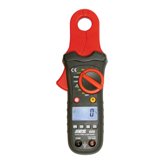
#688 PREMIUM True
RMS Low Current
Clamp Meter
Safety
International Safety Symbols
This symbol, adjacent to another symbol or terminal, indicates the user must refer
to the manual for further information.
This symbol, adjacent to a terminal, indicates that, under normal use, hazardous
voltages may be present
Double insulation
SAFETY NOTES
Do not exceed the maximum allowable input range of any function
Do not apply voltage to meter when resistance function is selected.
Set the function switch OFF when the meter is not in use.
WARNINGS
Set function switch to the appropriate position before measuring.
When measuring volts do not switch to current/resistance modes.
When changing ranges using the selector switch always disconnect the test leads from
the circuit under test.
Do not exceed the maximum rated input limits.
CAUTIONS
Improper use of this meter can cause damage, shock, injury or death. Read and
understand this user manual before operating the meter. Always remove the test leads
before replacing the battery. Inspect the condition of the test leads and the meter itself for
any damage before operating the meter. Repair or replace any damage before use.
Use great care when making measurements if the voltages are greater than 25VAC rms or
35VDC. These voltages are considered a shock hazard. Remove the battery if the meter is
to be stored for long periods.
Always discharge capacitors and remove power from the device under test before
performing Diode, Resistance or Continuity tests.
Voltage checks on electrical outlets can be difficult and misleading because of the
uncertainty of connection to the recessed electrical contacts. Other means should be used
to ensure that the terminals are not "live".
If the equipment is used in a manner not specified by the manufacturer, the protection
provided by the equipment may be impaired.
Function
A
V DC, V AC
Frequency, Resistance, Diode, Continuity ,
Capacitance Test
Temperature (℃/℉)
Input Limits
Maximum Input
80A DC/AC
600V DC/AC
250V DC/AC
250V DC/ AC
Advertisement

Related Manuals for ESI 688 PREMIUM


Summary of Contents for ESI 688 PREMIUM
- Page 1 Safety #688 PREMIUM True International Safety Symbols RMS Low Current This symbol, adjacent to another symbol or terminal, indicates the user must refer to the manual for further information. Clamp Meter This symbol, adjacent to a terminal, indicates that, under normal use, hazardous...
- Page 2 Meter Description Specifications 1. Current clamp Function Range & Resolution Accuracy (% of reading) 2. Clamp trigger DC Current 5000mA DC ± (2.8% + 20 digits) 3. Rotary Function swith 80.0 A DC ± (3% + 8 digits) 4. Data Hold button DC Current ranges specified from 5% to 100% of range 5.
- Page 3 Press the PEAK button again, Pmin will display. The display will now update and indicate the lowest negative peak. Clamp size Opening 0.75" (19mm) approx Press the PEAK button again, a blinking “MAX MIN” will appear. The meter will display the Diode Test Test current of 0.3mA typical;...
- Page 4 For resistance measurements, read the resistance on the LCD display. For continuity measurements, press the mode button until the •))) appears. Follow the same instructions as above - for Continuity tests, if the resistance is < 50, a Battery Replacement tone will sound.