RadioLink AT9S Pro Instruction Manual
10/12 channels transmitter
Hide thumbs
Also See for AT9S Pro:
- Manual (83 pages) ,
- Instruction manual (82 pages) ,
- Quick start manual (12 pages)

Related Manuals for RadioLink AT9S Pro


Summary of Contents for RadioLink AT9S Pro
- Page 1 AT9S Pro (DSSS&FHSS&CRSF) Instruction Manual (Helicopter/Fixed-wing/Glider/Multirotor/Car/Boat/Robot) 10/12 channels transmitter CE FCC RoHS...
-
Page 2: Usage Notice
Multi-rotor must check whether the motor rotation direction is normal. Always be sure about turning off the receiver before the transmitter. The AT9S Pro transmitter cannot be restored to factory settings, only the currently used model can be reset in "BASIC MENU"-"MODEL TYPE"... -
Page 3: Configuration List
RadioLink Electronic Limited www.radiolink.com Configuration List AT9S Pro Transmitter×1 R9DS Receiver×1 Lanyard×1 Packing Box×1 Instruction Manual×1 THR Return Accessories×1 Technical Parameters... -
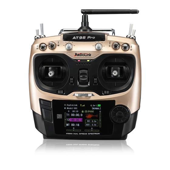
Page 4: Basic Introduction
RadioLink Electronic Limited www.radiolink.com Basic Introduction The picture above takes the left-hand throttle as an example. :GND -NC :No Output -VCC:Voltage Output(7.4-18V) -OUT:Signal Out: PPM/SBUS/CRSF -IN :RSSI Signal Input... - Page 5 Toggle switch, AT9S Pro has 4 two-stage switches, 3 three-stage switches and a reset switch. All switches can be customized function setting. For details, please refer to www.radiolink.com.
- Page 6 THROTTLE BOTTOM POSITION ALARM function. AT9S Pro factory default low voltage alarm is 8.6V. If the battery used is lower than 8.6V, the screen will sound an alarm (***WARNING*** TX LOW POWER!), and you can set the TX-ALARM in the BASIC MENU-PARAMETER according to the actual battery voltage value.
- Page 7 1. Put the transmitter and the receiver close to each other (about 50 centimeters). 2. Power on AT9S Pro and R9DS, the LED of R9DS will be on. 3. There is a black binding button (ID SET) on the side of receiver. Press the button for more than 1 second and release, the RED (by default, could be Purple for SBUS&PWM...
- Page 8 RadioLink Electronic Limited www.radiolink.com Installment of Antenna Receiver Antenna Installment 1. Keep antennas as straight as possible, or the effective control range will reduce. 2. Big models may contain metal parts that influence signal emission. In this case, antenna should be positioned at one side of the model to ensure the best signal status in all circumstances.
- Page 9 CRSF cable is sold separately. You can login to the RadioLink official website for details. Power on the AT9S Pro - Long press Mode button to enter BASIC MENU - Rotate the PUSH button to select SYSTEM and press Push button to enter - Rotate the PUSH button to select OUT and change it as CRSF.