Table of Contents
Advertisement
Quick Links
Advertisement
Table of Contents

Related Manuals for Honeywell NOTIFIER LCD6000A


Summary of Contents for Honeywell NOTIFIER LCD6000A
- Page 1 LCD6000A Installing Manual Remote Panel...
-
Page 2: Table Of Contents
INDICE DETECTION SYSTEM LIMITS GENERAL DESCRIPTION FUNCTIONS INSTALLATION FRONT PANEL CONTROLS USER INTERFACE DESCRIPTION Normal condition Alarm zone events condition Condition with zone events fault Condition with excluded zone events PROGRAMMING MENU SERIAL LINE RS485 SHIELDED CABLE AND GROUNDING LDC-6000A BOARD TOPOGRAPHIC CN1 TERMINAL BOARD ELECTRICAL FEATURES POWER SUPPLY... -
Page 3: Detection System Limits
N.B.: Before installing LCD-6000A panel read carefully this manual. WARNING: This manual refers to all the features available in software revision indicated on manual’s cover. DETECTION SYSTEM LIMITS A security or fire detection system is useful for timely advice of each dangerous event, like fire, theft, intrusion and in some cases can provide automatic event management (evacuation messages diffusion, automatic extinguishing systems, CCTV plants interfacing, door and accesses lock, automatic warning of authorities etc.) but in any case, does not assure protection against property damage or resulting from fire or... -
Page 4: General Description
GENERAL DESCRIPTION DESCRIPTION LCD-6000A is a remote panel that allows events visualization, relating to sensors, modules or selected zones and this way allows to divide the system. Events programming is performed by PC thanks to PK software. A maximum of 32 events can be selected for displaying, referred to these devices: ... -
Page 5: Functions
FUNCTIONS LCD-6000A can execute the following functions: Local ACK Lamp test Buzzer test Peripheral address programming FUNCTIONING Needs local programming to assign peripheral address. LCD-6000A shows time, date and events previously programmed, that come from AM series control panels. Technical features ... -
Page 6: Installation
INSTALLATION Dimensions for wall-mount The panel is designed to be wall- mounted through 4 self-blocking nogs (stone walls) or self-tapping screws (pre- built panels etc.) Screws diameter must be 5mm max. We advice not to install the panel near heating sources (radiators etc.) Plug-in the cable into CN1 Fix the incoming cable with a bend. -
Page 7: Front Panel Controls
FRONT PANEL CONTROLS PROGRAMMING BUZZER SILENCING: Pressing this key results in LCD6000A buzzer silencing Buzzer Test: LAMP-TEST: pressing this key will enable pressing this key lamp-test Buzzer for a few seconds. function is launched (all led blink for a few seconds). -
Page 8: User Interface Description
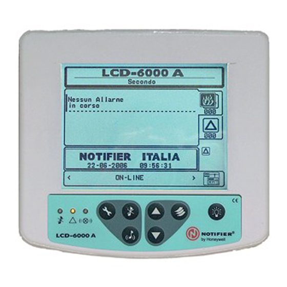
USER INTERFACE DESCRIPTION Normal condition The following screen is shown when on the LCD6000A panel no trouble is present (alarms and faults): User programmable label (max 32 characters) Alarm zones counter Fault zones counter Excluded zone signalling Date - Time icon* RS485 serial connection status. -
Page 9: Alarm Zone Events Condition
Alarm zone events condition The following screen is shown when in the control panel a zone in alarm condition is present and LCD- 6000A is programmed to show these events. Area for 1st event’s visualization First zone in alarm Alarm zones counter Label programmed for the zone date and time... -
Page 10: Condition With Zone Events Fault
Condition with zone events fault The following screen is shown when the control panel is in fault condition. Also fault events are initially shown by zone. Date and time of the first zone fault event Fault zones counter First event visualization area With the arrows ... - Page 11 To enter into excluded zones list visualization you need to: Press key to enter the main menu Use the arrow keys to select “Exclusion” voice and press “Lists” key to confirm selection In this window, the number of excluded zones is shown. Press “Lists”...
-
Page 12: Programming Menu
PROGRAMMING MENU Pressing and holding and typing the 4th level password, user can enter programming menu, where he can perform LCD-6000A start-up configuration and modify programming. The following menu is shown: Use the arrow keys to select the function you want to modify and press “Lists”... -
Page 13: Serial Line Rs485
Buzzer volume Selecting “Buzzer Volume” entry with the arrow keys and pressing Lists key to confirm , user can program buzzer volume in case of alarm and fault. Led test Selecting “Led test” entry with the arrow keys and pressing Lists key to confirm, the panel performs lamp-test function. -
Page 14: Shielded Cable And Grounding
Shielded cable and grounding During installing you need to consider consequences of remote grounding. When you connect RS-485 devices, if a Schermo: ground cable (drain) is available, Connettere al this MUST NOT be connected at telaio con un anello M5 e vite both the ends to devices’... -
Page 15: Cn1 Terminal Board
CN1 terminal board N° Desc ription Features Notes LIN – RS-485 slave serial line Used for LCD-6000A slave connection RS-485 slave serial line LIN + RS-485 serial line LIN – Reference negative for RS-485 serial line RS-485 serial line LIN + Power input + 24Vcc ELECTRICAL FEATURES... - Page 16 E-mail: notifier@notifier.it A Honeywell company Every care has been taken in the preparation of this data sheet but no liability can be accepted for the use of the information therein. Design features may be changed or amended without prior notice.