Table of Contents
Advertisement
Quick Links
Advertisement
Table of Contents

Related Manuals for Contec MC-310B-DC355

Summary of Contents for Contec MC-310B-DC355
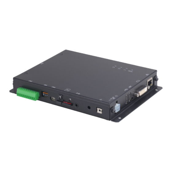
- Page 1 Industrial Multi Controller MC-310B-DC355 User’s Manual CONTEC CO.,LTD.
- Page 2 Check Your Package Thank you for purchasing the CONTEC product. The product consists of the items listed below. Check, with the following list, that your package is complete. If you discover damaged or missing items, contact your retailer. Product Configuration List - Unit [MC-310B-DC355]…1...
-
Page 3: Copyright
No part of this document may be copied or reproduced in any form by any means without prior written consent of CONTEC CO., LTD. CONTEC CO., LTD. makes no commitment to update or keep current the information contained in this document. -
Page 4: Table Of Contents
(7) Speaker connecting terminal ....................11 (8) SD slot ..........................12 (9) USB port (miniB) ......................... 12 (10) DIP SW ..........................13 (11) Communication connector ....................13 (12) External extended connector ....................15 LED ..............................19 LED Display ..........................19 MC-310B-DC355... - Page 5 Specification ............................23 Hardware or Factory Setting ...................... 23 Functional Specification ......................24 Installation Environment Requirements ..................25 Physical dimensions ........................25 Battery ............................... 26 Battery Specification ........................26 Removing the battery ......................... 26 Disposing the battery ........................26 MC-310B-DC355...
-
Page 6: Introduction
Display output : 1280 x 720(720p), 1024 x 768(XGA), 800 x 600(SVGA), 640 x 480(VGA) Analog input : Equipped with single-ended input, input range±5V, Resolution 12 bit Digital input : Equipped with opto-coupler isolated input (for current sink output) Digital output : Equipped with opto-coupler isolated open collector output (current sink type) MC-310B-DC355... -
Page 7: Accessories (Option)
Screw upright terminal panel” is used to prevent terminal screws from falling off. “ Check the CONTEC’s Web site for more information on these options. How to Use Accessories For more information on image output, Line out and software setup, visit the resource center ( http://www.contec.co.jp/mc ). -
Page 8: Customer Support
You can download updated driver software and differential files as well as sample programs available in several languages. Note! For product information Contact your retailer if you have any technical question about a CONTEC product or need its price, delivery time, or estimate information. How to Obtain Service For replacement or repair, return the device freight prepaid, with a copy of the original invoice. -
Page 9: Safety Precautions
WARNING indicates a potentially hazardous situation which, if not avoided, could WARNING result in death or serious injury. CAUTION indicates a potentially hazardous situation which, if not avoided, may CAUTION result in minor or moderate injury or in property damage. MC-310B-DC355... -
Page 10: Handling Precautions
Before inserting/removing an SD card or plugging/unplugging connectors or cables, be sure to unplug the power cable. Do not modify this product. CONTEC will bear no responsibility for any problems or issues resulting from the modification of this product. In the event of failure or abnormality (foul smells or excessive heat generation), unplug the power cable immediately and contact your retailer. - Page 11 It may cause a trouble in recognizing and operating the device according to the kind of USB hub. If you use the USB hub, we encourage you to take advantage of the CONTEC’s product loan service to confirm operation before purchasing.
-
Page 12: Environment
When disposing of the product, follow the disposal procedures stipulated under the relevant laws and municipal ordinances. * This product is backed by a Lithium primary battery, so please be careful about its disposal. * For more information on removing a battery, see "Removing the battery" in chapter 4. MC-310B-DC355... - Page 13 1. Introduction MC-310B-DC355...
-
Page 14: Each Component Function
(1) LAN port: Connector for LAN (100BASE-TX). (2) DVI-D: Connector for display. The image output please refers to resource center (http://www.contec.co.jp/mc). (3) Reset switch: Used to reset this product. (4) USB port: Accepts USB flash drives and similar storage devices for saving data. Do not use during operation in environments with a lot of electromagnetic interference. -
Page 15: Component Function
It is a connector for display connection. The screen resolutions supported by this product are 1280 x 720(720p), 1024 x 786(XGA), 800 x 600(SVGA), and 640 x 480(VGA). For more information on image output, visit the resource center (http://www.contec.co.jp/mc). Pin No. Signal name Pin No. -
Page 16: Usb Port
It may cause a trouble in recognizing and operating the device according to the kind of USB hub. If you use the USB hub, we encourage you to take advantage of the CONTEC’s product loan service to confirm operation before purchasing. -
Page 17: Sd Slot
When connected to the host, it works as a debug console. Do not use it while the controller is being operated in an environment where the noise level is high. Pin No. Signal name VBUS -Data (D-) +Data (D+) ID (NC) MC-310B-DC355... -
Page 18: Dip Sw
TXD is only used for data transmission ; the With above setting, RTS and CTS are connected in sending and receiving modes should be switched this product. over using the modem control register. Communication is available without wiring of RTS and CTS. MC-310B-DC355... - Page 19 The following examples show the status when terminators are inserted/not inserted for half-duplex and full duplex settings respectively. Not inserted Factory setting - Half duplex [ A or D ] Terminator Terminator (bit 9) (bit 9) Not Inserted Inserted B or C Not Inserted Figure 2.4. Party Line Connection MC-310B-DC355...
-
Page 20: External Extended Connector
DI 03 AI 00 N.C. AI GND DO COM+ AI 01 N.C. AI GND DO 00 AI 02 N.C. AI GND DO 01 AI 03 N.C. DO 02 AI GND N.C. DO 03 N.C. N.C. COM+/- : 12 - 24VDC MC-310B-DC355... - Page 21 (ready to accept current sinking output signals). This product therefore requires an external power supply to drive the inputs. The power requirement for each input pin is about 5.1 mA at 24 VDC (about 2.6 mA at 12 VDC). MC-310B-DC355...
- Page 22 A PolySwitch-based overcurrent protector is provided. When the overcurrent protector works, the output section of this product is temporarily disabled. If this is the case, turn off the power to the PC and wait for a few minutes, then turn them on back. MC-310B-DC355...
- Page 23 When the distance between the signal source and the board is long or you want to increase the noise tolerance, a shield cable is suggested. Connect a cable core to a signal wire and a braided shield to a ground. Figure 2.10. Single-ended Input Connection (Shield Cable) MC-310B-DC355...
-
Page 24: Led
OS is running. (Initial setting) / Controllable from program * L3 (red) Controllable from program * For more information on LED control, visit the resource center (http://www.contec.co.jp/mc). Order of LED lighting on start-up (1) After power activation : ON (POW, L1, L2, L3) - Page 25 2. Each Component Function MC-310B-DC355...
-
Page 26: Before Using The Product For The First Time
CAUTION When operating the product in a high temperature environment, be careful to sufficiently release the heat inside the main unit even while it is running within the specified temperature range. Figure 3.1. How to attach bracket fittings MC-310B-DC355... -
Page 27: Distances Between This Product And Its Vicinity
Ensure a clearance between this product and surrounding equipment of at least 50mm for the top and bottom and front, side. Figure 3.2. Distances between this product and its vicinity Software Setup For more information on software setup, visit the resource center (http://www.contec.co.jp/mc). MC-310B-DC355... -
Page 28: Specification
SSH. Default LAN settings are shown in the table on the right. The factory default password for the root user is root. You must change this password the first time this product is used. MC-310B-DC355... -
Page 29: Functional Specification
Status 3(L3)/LAN port (Link / Act , Speed) Switch DIP Switch, Reset Switch RTC built in CPU, The real-time clock is accurate within ±1 minutes (at 25°C) per month Rated input voltage 12 - 24VDC ± 5% Power supply Max. input current 15W (Max.) MC-310B-DC355... -
Page 30: Installation Environment Requirements
Not to be excessive Corrosive gases None Allowable instantaneous Less than 17ms (100VAC at 25°C), voltage drop Automatically reset when low voltage is detected Physical dimensions (mm) 172.6(W) x 138.0(D) x 27.0(H) (No protrusions) Weight 650g Physical dimensions Figure 4.2. Physical dimension MC-310B-DC355... -
Page 31: Battery
(4) Cut the cable tie with scissors and remove the battery. (5) Unplug the connector of the wire that is connected to the battery from the PCBA (printed circuit board assembly). Figure 4.3. Removing the battery Disposing the battery Dispose the removed battery properly as instructed by local government. MC-310B-DC355... - Page 33 September 2019 Edition 3-9-31, Himesato, Nishiyodogawa-ku, Osaka 555-0025, Japan English https://www.contec.com/ No part of this document may be copied or reproduced in any form by any means without prior written consent of CONTEC CO., LTD. [09302019] [10092012] Management No. NA02212 [09302019_ver2] Parts No.