Table of Contents
Advertisement
Available languages
Available languages
Safe Operation Practices • Set-Up • Operation • Maintenance • Service • Troubleshooting • Warranty
O
'
M
peratOr
s
anual
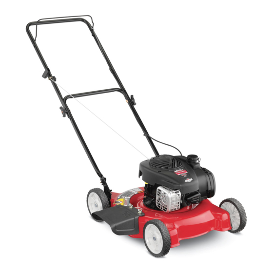
Push Mower — Model Series 02B
WARNING
READ AND FOLLOW ALL SAFETY RULES AND INSTRUCTIONS IN THIS MANUAL
BEFORE ATTEMPTING TO OPERATE THIS MACHINE.
FAILURE TO COMPLY WITH THESE INSTRUCTIONS MAY RESULT IN PERSONAL INJURY.
MTD LLC, P.O. BOX 361131 CLEVELAND, OHIO 44136-0019
Form No. 769-26344
(October 13, 2021)
Advertisement
Table of Contents

Related Manuals for MTD 02B Series


Summary of Contents for MTD 02B Series
- Page 1 READ AND FOLLOW ALL SAFETY RULES AND INSTRUCTIONS IN THIS MANUAL BEFORE ATTEMPTING TO OPERATE THIS MACHINE. FAILURE TO COMPLY WITH THESE INSTRUCTIONS MAY RESULT IN PERSONAL INJURY. MTD LLC, P.O. BOX 361131 CLEVELAND, OHIO 44136-0019 Form No. 769-26344 (October 13, 2021)
-
Page 2: Table Of Contents
How-To video; you can seek help from the experts. Have your full model number and serial number ready. Choose from the options below: Web: www.mtdproducts.com/equipment/mtdproducts ◊ ◊ Phone: (800) 800-7310 ◊ Mail: MTD LLC • P.O. Box 361131 • Cleveland, OH • 44136-0019... -
Page 3: Safe Operation Practices
Important Safe Operation Practices WARNING: This symbol points out important safety instructions which, if not followed, could endanger the personal safety and/or property of yourself and others. Read and follow all instructions in this manual before attempting to operate this machine. Failure to comply with these instructions may result in personal injury. - Page 4 Never over fill fuel tank. Fill tank to no more than 1” (2.5 Do not put hands or feet near rotating parts or under the cm) below bottom of filler neck to allow space for fuel cutting deck. Contact with the blade(s) can amputate expansion.
- Page 5 Children Do not operate the mower under any conditions where traction or stability is in question. Always be sure of your Tragic accidents can occur if the operator is not alert to the footing. A slip and fall can cause serious personal injury. If presence of children.
- Page 6 Service Grass catcher components and the discharge cover are subject to wear and damage which could expose moving Keep the mower in good working order. Replace worn or parts or allow objects to be thrown. For safety protection, damaged parts. frequently check components and replace immediately with original equipment manufacturer’s (O.E.M.) parts only.
- Page 7 Safety Symbols This page depicts and describes safety symbols that may appear on this product. Read, understand, and follow all instructions on the machine before attempting to assemble and operate. Symbol Description WARNING – READ THE OPERATOR’S MANUAL(S) - Read, understand and follow all the safety rules and instructions in the manual(s) and on the mower before attempting to operate this mower.
- Page 8 2 — i ection mportant peration racticeS...
-
Page 9: Assembly & Set-Up
Assembly & Set-Up Contents of Carton • Lawn Mower (1) • Chute Deflector (1) • Hardware Pack (1) • Lawn Mower Operator’s Manual (1) • Engine Operator’s Manual (1) • Oil (1) • Registration Card (1) Hardware Pack Group 1 Qty. - Page 10 Locate the hairpin clip on the pivot stud on each side of The rope guide is attached to the right side of the upper lower handle. handle. See Figure 3-4. Loosen the wing nut (a) which secures the rope guide. Remove hairpin clip (a) from hole at end of stud.
- Page 11 Adjustments Chute Deflector NOTE: Use the hardware in Group 2 to complete the following Cutting Height steps. Remove the shoulder screws (a), washers (b) (front wheels Align the holes on the chute deflector with the only), and nuts (c) from the wheels. See Figure 3-6. corresponding holes on the deck surface.
-
Page 12: Controls & Features
Controls and Features Blade Control Primer Recoil Starter Figure 4-1 Primer Blade Control The primer is located on the left side of the The blade control is attached to the upper handle of the mower. engine. The primer is used to pump gas into Depress and squeeze it against the upper handle to operate the the carburetor and aid in starting the engine. -
Page 13: Operation
Operation Starting Engine WARNING: Be sure no one other than the operator is standing near the lawn mower while starting engine or operating mower. Never run engine indoors or in enclosed, poorly ventilated areas. Engine exhaust contains carbon monoxide, an odorless and deadly gas. -
Page 14: Maintenance & Adjustment
Maintenance & Adjustments Maintenance Deck Care Clean underside of the mower deck after each use to prevent General Recommendations build-up of grass clippings or other debris. Follow steps below • Always observe safety rules when performing any for proper cleaning. maintenance. -
Page 15: Service
Service Blade Care WARNING: An unbalanced blade will cause excessive vibration when rotating at high speeds. It WARNING: When removing the cutting blade for may cause damage to mower and could break sharpening or replacement, protect your hands with causing personal injury. a pair of heavy gloves or use a heavy rag to hold the Lubricate the engine crankshaft and the inner surface of blade. -
Page 16: Troubleshooting
Troubleshooting Problem Cause Remedy Engine fails to start 1. Blade control disengaged. 1. Engage blade control. 2. Spark plug boot disconnected. 2. Connect wire to spark boot. 3. Fuel tank empty or stale fuel. 3. Fill tank with clean, fresh gasoline. 4. -
Page 17: Replacement Parts
Replacement Parts Component Part Number and Description 759-3336 Spark Plug BS-799579 Air Filter Cartridge BS-799585 Fuel Tank Cap 734-04063B Wheel 731-0064 Discharge Chute 942-0640 Mulching Blade (800) 800-7310 or (330) 220-4683 Phone to order replacement parts or a complete Parts Manual (have your full model number and serial number ready). -
Page 18: Attachments & Accessories
Attachments & Accessories Component Model Number and Description 490-850-0005 Blade Removal Tool — Holds blade in place for faster, safer removal. SPW-134 Spark Plug Wrench — Duel ended wrench to serve multiple uses. Fits ¾” or 13⁄16” hex plug. 490-850-0008 Oil Siphon —... - Page 19 Component Model Number and Description 22216 STA-BIL® fuel Stabilizer, 32 oz — Treats 80 gallons of fuel. Keeps stored fuel fresh for quick, easy starts. Prevents corrosion from moisture and ethanol-induced attraction. Prevents gum and varnish. 490-290-0012 Mower Cover — Protects your mower against sun, rain and dust damage.
-
Page 20: Warranty
MANUFACTURER’S LIMITED WARRANTY FOR The limited warranty set forth below is given by MTD LLC with Log splitter pumps, valves, and cylinders have a separate respect to new merchandise purchased and used in the United one- year warranty. States and/or its territories and possessions, and by MTD Products... -
Page 21: Spanish
Podadora de Empuje — Modelo 02M Modelo 11A-02M2329 ADVERTENCIA LEA Y SIGA TODAS LAS INSTRUCCIONES DE ESTE MANUAL ANTES DE PONER EN FUNCIONAMIENTO ESTA MÁQUINA. SI NO RESPETA ESTAS INSTRUCCIONES PUEDE PROVOCAR LESIONES PERSONALES. MTD LLC, P.O. BOX 361131 CLEVELAND, OHIO 44136-0019... - Page 22 Los números de teléfono, dirección cuidadosamente y en todo momento las prácticas de seguridad del sitio web y dirección postal de la Asistencia al Cliente de MTD recomendadas, y hacérselas seguir a cualquier otra persona que se encuentran en esta página. Queremos garantizar su entera opere la máquina.
- Page 23 Medidas importantes de seguridad ADVERTENCIA: La presencia de este símbolo indica que se trata de instrucciones importantes de seguridad que se deben respetar para evitar poner en peligro su seguridad personal y/o material y la de otras personas. Lea y siga todas las instrucciones de este manual antes de poner en funcionamiento esta máquina.
- Page 24 Esté atento a la cortadora de césped y a la dirección de Si la cortadora de césped comienza a vibrar de forma descarga de los aditamentos y no apunte la descarga de la extraña, detenga el motor y busque inmediatamente la cortadora en dirección a nadie.
- Page 25 Niños Siempre corte el césped de forma transversal a la pendiente, nunca hacia arriba y hacia abajo. Si el operador no está atento a la presencia de niños, se La cortadora de césped podría acelerarse al colocarla pueden producir accidentes trágicos. Por lo general a los cuesta abajo, siempre debe colocarla cuesta arriba.
- Page 26 Nunca llene los recipientes en el interior de un vehículo o Mantenga todas las tuercas, pernos y tornillos bien camión o caja de remolque con recubrimientos plásticos. ajustados para asegurarse de que la máquina se en Siempre ubique los recipientes en el piso, lejos del vehículo uentra en condiciones de funcionamiento seguras.
- Page 27 Símbolos De Seguridad Esta página representa y describe la seguridad los símbolos que pueden parecer en este producto. Lea, comprenda, y siga todas instrucciones de la máquina antes de intentar ensamblar y operar. Símbolo Descripción ADVERTENCIA - LEA EL MANUAL DEL OPERADOR - Lea, entienda y cumpla todas las reglas e instrucciones de seguridad que se incluyen en el manual y sobre la cortadora de césped antes de intentar utilizar esta cortadora.
- Page 28 2 — M ección edidaS iMportanteS de Seguridad...
- Page 29 Montaje y Configuración Contenido de la caja • Una Podadora • Uno Manual de Operador • Uno Manual de Operador de Motor • Uno Paquete de Hardware • Uno Deflector del Canal • Uno Botella del Aceite Paquete de Hardware Grupo 1 Cantidad 2 Cantidad 2...
- Page 30 Saque el pasador de horquilla de este orificio. Vea la La guía de la cuerda está unida al costado derecho de Figura 3-2. la manija superior. Vea la Figura 3-4. Afloje la tuerca de mariposa que sujeta la guía de la cuerda. Figura 3-2 Figura 3-4 Inserte el pasador de horquilla en el orificio en el...
- Page 31 Ajustes Canal Deflector NOTA: Use los elementos de ferretería del Grupo 2 para Altura de Corte completar los pasos siguientes. Saque de las ruedas los pernos del carro y los elementos de Alinee los orificios en el canal deflector con los orificios ferretería relacionados.
- Page 32 Controles Y Características Control de cuchilla Cebador Arrancador de retroceso Figura 4-1 Control de Cuchilla Cebador El control de la cuchilla está unido a la manija superior. Presione El cebador se encuentra en el lado izquierdo la manija de control de la cuchilla contra la manija superior para del motor.
- Page 33 Funcionamiento Encendido del Motor ADVERTENCIA: Asegúrese que ninguna persona aparte del operador permanezca cerca de la podadora mientras arranca el motor u opera la misma. Nunca encienda un motor en espacios cerrados o en una zona con poca ventilación. El escape del motor contiene monóxido de carbono, un gas inodoro y letal.
- Page 34 Mantenimiento Y Ajustes Mantenimiento Siga el manual adjunto del motor para conocer las instrucciones y el programa de lubricación del mismo. Recomendaciones Generales Cuidado de la cubierta • Respete siempre las reglas de seguridad cuando realice Debe limpiar la parte inferior de la plataforma de la podadora tareas de mantenimiento.
- Page 35 Servicio Cuidado de la Cuchilla Lubrique el cigüeñal del motor y la superficie interna del adaptador de la cuchilla con aceite ligero. Deslice el ADVERTENCIA: Cuando saque la cuchilla de corte adaptador de la cuchilla sobre el cigüeñal del motor. Instale la cuchilla con el lado marcado “Bottom”...
- Page 36 Solución de problemas Problema Causa Remedio El motor no arranca 1. El control de lámina se retiró. 1. Contratar el control de lámina. 2. Alambre de bujía desconectado. 2. Unir el alambre a la bujía. 3. Depósito de combustible combustible vacío 3.
- Page 37 Problema Causa Remedio Demasiada vibración 1. Cuchilla floja o desequilibrada. 1. Apriete la cuchilla y el adaptador. Equilibre la cuchilla. 2. Cuchilla abollada. 2. Consulte a un distribuidor autorizado. Corte desigual 1. La posición de las ruedas no es correcta. 1.
- Page 38 Notas...
- Page 39 9 — n ection otaS...
- Page 40 El daño resultante por la instalación o el uso de piezas, accesorios las piezas de acuerdo con su identificación. Ninguna otra o aditamentos no aprobados por MTD para su uso con el(los) garantía expresa, ni oral ni escrita, excepto la mencionada producto(s) incluido(s) en este manual anulará...