
Related Manuals for Bogen NQ-A2060-G2


Summary of Contents for Bogen NQ-A2060-G2
- Page 1 2-Channel Audio Power Amplifier Configuration Guide NQ-A2060-G2, NQ-A2120-G2, NQ-A2300-G2 © 2021 Bogen Communications, Inc. All rights reserved. 740-00159 210811...
-
Page 2: Table Of Contents
Contents Contents ............. ii List of Figures . -
Page 3: List Of Figures
List of Figures Figure 1. Nyquist Appliance Login..........1 Figure 2. - Page 4 List of Tables Table 1. Appliance Dashboard Fields......... . .2 Table 2.
-
Page 5: Configuring The Two-Channel Audio Power Amplifiers
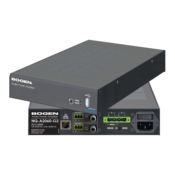
Configuring the Two-Channel Audio Power Amplifiers Bogen’s Nyquist-based networked two-channel audio power amplifiers (NQ-A2060-G2, NQ-A2120-G2, NQ-A2300-G2) support small, medium, and large Nyquist intercom solu- tions in schools and in commercial paging and public address solutions. Available in 120-, 240-, and 600-watt models, the audio power amplifiers provide flexibil- ity and versatility without the need for add-on modules. -
Page 6: Using The Dashboard
At the Nyquist Appliance Login page, enter username and password, and then select Login. The default username is admin; the default password is bogen. The dashboard for the selected appliance appears. Figure 2. 2-Channel Power Amplifier Dashboard Using the Dashboard The dashboard displays the following fields: Table 1. -
Page 7: Standalone Operation
Standalone Operation mode is ideal for scenarios that do not require the full functionality provided by an integrated system, such as the Bogen C4000 or E7000 Series, but has the ability to provide paging, multi-channel audio processing, and a SIP endpoint for a PBX/... -
Page 8: Updating Firmware
Check for Updates button checks the Bogen website for the latest firmware version available. If a version newer than the one currently installed is found, it is downloaded to the appliance. Alternatively, if you already have a firmware file you would like to install to the appli-... -
Page 9: Table 3. Firmware Update Settings
Check for Updates Available only when the appliance is configured for Standalone mode. Checks the Bogen website for the latest firmware version available. and if it finds a version newer than what is currently installed, downloads it to the appliance. -
Page 10: Network Settings Tab Parameters
Network Settings Tab Parameters Network settings can be configured dynamically by the Nyquist server or manually by using the appliance’s web UI. To manually configure network settings: On the appliance web UI’s main page, select Network Settings. Select your desired network settings. Select Save. -
Page 11: Table 4, Network Settings
Table 4, Network Settings IP Address Identifies the IP address assigned to the appliance. Netmask Identifies the subnetwork subdivision of an IP net- work. Gateway Identifies the address, or route, for the default gate- way. VLAN ID Identifies the Virtual Local Area Network (VLAN) for this appliance. - Page 12 Table 4, Network Settings (Continued) TFTP Server from DHCP “Yes” means the device will use the DHCP option 66 value to retrieve an address for the TFTP Server from DHCP. “No” means the device will ignore the DHCP option 66 value and use the manually configured value of the TFTP Server (see above).
-
Page 13: Configuration Settings Tab Parameters
Configuration Settings Tab Parameters The easiest way to configure Nyquist appliances is to obtain configuration settings from the Nyquist server by selecting Get Configuration From Server. However, you can man- ually configure an appliance through the appliance’s Web UI when Standalone Operation is enabled (see "Standalone Operation Configuration Settings”... -
Page 14: Table 5. Configuration Settings (Standalone Disabled)
Table 5. Configuration Settings (Standalone disabled) Get Configuration from Retrieves configuration settings (i.e., web username, server, and local port) from the TFTP server specified in Server the Network Settings (see "Network Settings Tab Param- eters” on page 6). Web Username Displays the username of the current user. -
Page 15: Standalone Operation Configuration Settings
Standalone Operation Configuration Settings Figure 6. Appliance Configuration Settings (Standalone enabled) The following table describes the Configuration Settings tab settings when Standalone Operation is enabled for this device:... -
Page 16: Table 6. Configuration Settings (Standalone Enabled)
Table 6. Configuration Settings (Standalone enabled) Device Type Displays the type of this device. Device Name Provide a name for this device. Web Username Provide a web username for this appliance. Web Password Provide a web password for logging into the appliance. Web Confirm Password Re-enter the password used to log into the appliance. - Page 17 Table 6. Configuration Settings (Standalone enabled) SIP Password Specify the SIP registration password used to register Channel A or B with the SIP server. (Channel A/B) Cut Level Specify the intercom volume to be used for SIP calls over Channel A or B. (Channel A/B) This can be a value from -42 and 0 dB.
- Page 18 Codec Specifies the codec to be used when decoding audio. Select one of the following values: • G711 u-law • Intercom quality • A narrowband audio codec that provides toll-qual- ity audio at 64 kbps. The u-law version is primarily used in North America and Japan.
-
Page 19: Accessing Log Files
Note: Multicast Addresses should be ordered by priority, highest priority first. If multi- ple streams are active on the same channel simultaneously, the one with the highest priority will be played. Set the Sorting switch to Enabled and drag entries using the 4- way arrow symbols to drag entries up and down to rearrange the priorities. -
Page 20: Figure 7, Logs
Figure 7, Logs Available logs are described in the following table. If a log file is empty, however, it will not appear in the drop-down list of available logs. Table 7, Logs Description ampws.log Contains information about protection status and logs protection events with temperature information at the time of event. -
Page 21: Setting Dsp Parameters
Table 7, Logs (Continued) Description kern.log Contains information logged by the kernel and recent login information for all users. lastlog Contains information on the last login of each user. messages Contains messages generated by Nyquist. php5-fpm.log Contains errors generated by the PHP script. syslog Contains list of errors that occur when the server is run- ning and server start and stop records... - Page 22 Tip: The output levels of digital audio streams received over the network are controlled by the same slid- ers that control analog line input signals. You can use the DSP Router to adjust an analog signal level rel- ative to a digital signal level on the same channel. The digital signal, regardless of the source, is then conditioned, filtered, and enhanced via the DSP processors, and its level adjusted via the mixing board’s slider controls.
-
Page 23: Dsp Page
Note: The DSP page (including the mixing board and other DSP pages) can only be used by one browser session at a time. If another session is already connected and using this DSP page, the mixing board displayed will be disabled. Note: If two output connectors are configured for Bridge mode (A/B), the output chan- nel that corresponds to the second connector (B) will not appear on the mixing board interface. -
Page 24: Dsp Features
Table 9, DSP Features Amplifier Mute Eliminates low-level analog noise, such as the “pops” that can occur when the device is turned on or off. Compressor Lessens the dynamic range between the loudest and qui- etest parts of an audio signal. Delay Delays the signal by a specified number of milliseconds. -
Page 25: Setting The Channel Level
Table 9, DSP Features Status Provides real-time status for the amplifier, including which mode (2-channel or single channel bridge mode) the out- put is configured, channel output limits, and more. Reset button Present on almost all DSP screens other than the main mixer, this button will reset the DSP settings to the dis- played feature’s default setting. -
Page 26: Adjusting Volume Levels
Mute button will illuminate red. You can click the Mute button again to unmute the channel. Adjusting Volume Levels The vertical slider control can be used to adjust the channel’s output level in 1-dB incre- ments between -60 and +12 dB. The overall adjusted output level of the channel signal can be viewed on the VU meter, marked in 2-dB increments between -60 and 0 dB. -
Page 27: Figure 9. Amplifier Mute Settings
Figure 9. Amplifier Mute Settings To adjust the Amplifier Mute settings for a channel: On the appliance Web UI’s main page, select DSP. Select the Menu button for the channel. From the drop-down menu, select Amplifier Mute. Note: If you want to return to the factory settings, select the Reset icon that appears in the right corner. -
Page 28: Compressor
Table 10. Amplifier Mute Settings Threshold Sets the minimum threshold level that the signal must reach to allow the signal to be sent to the output channel. Threshold range is -135 to +21 dB. Status Indicates if channels A/B are in Amplifier Mute mode (On) or not (Off). -
Page 29: Table 11. Compressor Settings
Select Enable to apply the settings to the selected channel. Table 11. Compressor Settings Enable Enables or disables the compressor DSP effect for this channel. Threshold Sets the threshold level, which is the point where the signal activates the compressor circuit. The range is -135 to +21 dB. -
Page 30: Delay
Table 11. Compressor Settings Ratio Sets the compression ratio to be applied to the signal. For example, if the ratio is set for 6 (6:1), the input signal must increase by 6 dB for the output level to increase by 1 dB. -
Page 31: Figure 11. Delay Settings
Figure 11. Delay Settings To adjust the Delay settings for a channel: On the appliance Web UI’s main page, select DSP. Select the Menu button for the channel. From the drop-down menu, select Delay. Note: If you want to return to the factory settings, select the Reset icon that appears in the right corner. -
Page 32: Graphic Eq
Table 12. Delay Settings Clip LED Illuminates when the input signal is clipping. Input meter Indicates the strength of the input signal. Graphic EQ The graphic equalizer allows you to tailor the audio signal to optimize the frequency response of the sound system. The graphic equalizer parameters are set per channel. -
Page 33: High/Low Pass
Note: If you want to return to the factory settings, select the Reset icon that appears in the right corner. High/Low Pass High-pass filters allow signals that are higher than the specified frequency and attenuate signals that are lower. Low-pass filters allow signals that are lower than the specified fre- quency and attenuate signals that are higher. -
Page 34: Table 13. High/Low Pass Parameters
On the appliance Web UI’s main page, select DSP. Select the Menu button for the channel. From the drop-down menu, select High/Low Pass. Note: If you want to return to the factory settings, select the Reset icon that appears in the right corner. -
Page 35: Limiter
Table 13. High/Low Pass Parameters (Continued) Low-Pass (High Cut) This feature helps eliminate high-frequency noise (signals of 8000 Hz and above) such as background hiss and sibilance (excessive "S" in vocals, etc.) and is used primarily with microphone-level input. It is particularly effective when handheld microphones are used. -
Page 36: Figure 14. Limiter Settings
Figure 14. Limiter Settings To adjust the limiter settings for a channel: On the appliance Web UI’s main page, select DSP. Select the Menu button for the channel or select the Menu button for the Output. From the drop-down menu, select Limiter. Note: If you want to return to the factory settings, select the Reset icon that appears in... -
Page 37: Noise Gate
Table 14. Limiter Settings Threshold Sets the signal level at which the limiter is triggered. Any signal exceeding this threshold will be compressed to this level. The range is -24 to +24 dB. Decay Sets the rate for turn off of the limiter after the signal is below the threshold. -
Page 38: Figure 15. Noise Gate Settings
Figure 15. Noise Gate Settings To adjust the noise gate settings for a channel: On the appliance Web UI’s main page, select DSP. Select the Menu button for the channel. From the drop-down menu, select Noise Gate. Note: If you want to return to the factory settings, select the Reset icon that appears in the right corner. -
Page 39: Parametric Eq
Table 15. Noise Gate Settings Attack Sets how long it takes for the gate to open once the signal reaches the threshold level. Attack range is 1 to 500 ms. Hold Sets the length of time the gate will stay fully open after the signal reaches the threshold level. -
Page 40: Peak Limiter
To adjust the parametric equalizer settings for a channel: On the appliance Web UI’s main page, select DSP. Select the Menu button for the channel. From the drop-down menu, select Parametric Note: If you want to return to the factory settings, select the Reset icon that appears in the right corner. -
Page 41: Figure 17. Peak Limiter Settings
Tip: The Presets feature contains predefined Peak Limiter settings for a number of specific speakers. Figure 17. Peak Limiter Settings To adjust the Peak Limiter settings for a channel: On the appliance Web UI’s main page, select DSP. Select the Menu button for the channel. -
Page 42: Presets
Table 16. Peak Limiter Settings Enable Enables or disables the Peak Limiter DSP effect for this channel. Threshold Sets the threshold level, which is the point where the signal activates the compressor circuit. The range is -135 to +21 dB. Attack Sets how quickly or slowly compression will be applied to the signal once the audio signal goes above the... -
Page 43: Figure 18. Presets Settings
(JSON-encoded) files, which allows them to be backed up or shared between devices. Bogen has provided a number of predefined DSP presets. These configurations are defined and optimized for specific speakers. DSP presets can be selected and applied to each individual channel. Selecting a preset will apply the predefined settings for that channel, potentially overwriting any existing settings. -
Page 44: Table 17. Preset Settings
Prompts the user to select one or more preset configura- tion files from the local computer. These files must contain JSON-encoded DSP preset configurations that were previ- ously downloaded or provided by Bogen technical sup- port. Once uploaded, the new DSP preset configurations will be available for use. -
Page 45: Rms Limiter
RMS Limiter The primary purpose of the RMS Limiter is to protect the speakers from the thermal damage that can be caused by extended periods of excessive power usage. Any signal whose RMS level exceeds the threshold will be compressed, thereby reducing the signal. RMS Limiter uses the RMS (root mean square) level, which is proportional to the average amount of energy over a short period of time, to determine when a signal has... -
Page 46: Table 18. Rms Limiter Settings
Note: If you want to return to the factory settings, select the Reset icon that appears in the right corner. Make desired adjustments using the controls described in Table 18, “RMS Limiter Set- tings,” on page 42. Select Enable to apply the settings to the selected channel. Table 18. -
Page 47: Router
Router Router settings allow you to specify where to output a line input signal and how much to adjust its level. For each input, you can: • Adjust the Analog Input Gain. This adjusts the electronic gain for the input signal. •... -
Page 48: Settings
On the appliance Web UI’s main page, select DSP. Select the Menu button for any channel. From the drop-down menu, select Router. Enable the desired Inputs (green). Enable the desired Outputs (blue). Enable the output channels to which each input is to be routed (gray). Adjust the input, output, and routed channel gains (green, blue, and gray). -
Page 49: Figure 21. Settings Parameters For 2 Channel Mono
Figure 21. Settings Parameters for 2 Channel Mono To adjust the settings for a channel: On the appliance Web UI’s main page, select DSP. Select the Menu button for the channel. From the drop-down menu, select Settings. Note: If you want to return to the factory settings, select the Reset icon that appears in the right corner. -
Page 50: Signal Present
Signal Present You can configure the threshold level that a signal must reach before the signal LED is lit, as well as how long the LED will remain lit. You can configure this for each channel. Figure 22. Signal Present Parameters To adjust the Signal Present settings for a channel: On the appliance Web UI’s main page, select DSP. -
Page 51: Standby
Adjust the following settings as needed. Table 19. Signal Present Parameters Threshold Sets the minimum level the signal must reach before the signal LED is illuminated. Threshold range is -144 to +24 dB. Hold Sets the minimum number of milliseconds that the signal LED will remain illuminated. -
Page 52: Figure 23. Standby Settings
Figure 23. Standby Settings To adjust the Standby settings for a channel: On the appliance Web UI’s main page, select DSP. Select the Menu button for the channel. From the drop-down menu, select Standby. Note: If you want to return to the factory settings, select the Reset icon that appears in the right corner. -
Page 53: Status
Table 20. Standby Settings Enable Enables or disables the standby feature for the amplifier. Threshold Amp AB Sets the threshold level for channels A/B. If the signal level remains below this level for 200 sec- onds or longer, the amplifier is put into low power Standby mode. -
Page 54: Figure 24. Status For 2-Channel
Figure 24. Status for 2-Channel Figure 25. Status for Bridged Channel To view status for the power amplifier: On the appliance Web UI’s main page, select DSP. - Page 55 Select the Menu button for the channel. From the drop-down menu, select Status. The view only information that appears is described in the following table: Table 21. Status Switch Position Indicates the position of the Amplifier Mode switch located on the rear of the appliance. Bridged mode is typi- cally used when higher-power, single-channel operation with a high-impedance loudspeaker load is needed.