Advertisement
Quick Links
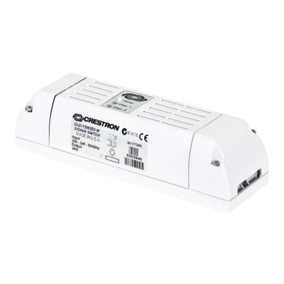
CLCI-1SW2EX-W
Wireless In-Ceiling Switch, 230 Vac
Installation Guide
Description
The CLCI-1SW2EX-W is a two-channel switch capable of controlling two independent,
230 Vac lighting loads. Its ultraslim design allows it to be installed in the ceiling, either next
to or near the xture. Powered by in NET EX
communicates wirelessly with the Crestron
and retro t applications. Additionally, the switch installs inline without requiring any special
wiring and can be controlled via a standard light switch.
CLCI-1SW2EX-W Speci cations
SPECIFICATION
Input Voltage
Load Ratings*
Number of Channels
Maximum Load per Channel
Switch Load Types
Environmental
Temperature
Humidity
* VA ratings are for input power to the transformer. If the input power requirements of the transformer are
unknown, use the bulb's wattage rating to determine proper rating.
Additional Resources
Visit the product page on the Crestron website (www.crestron.com)
for additional information and the latest rmware updates. Use a QR
reader application on your mobile device to scan the QR image.
Important Notes
CAUTION: Observe the following points:
• Install the CLCI-1SW2EX-W only on 10 A branch circuits.
• Install using wires that are a maximum of 2.5 mm
BS6004:2000/IEC 60245 and local electrical codes.
• Use the CLCI-1SW2EX-W with loads that have a power factor greater than 0.95.
NOTE: Record the serial number of the device before installation.
Refer to the CLC(I)-SERIES IMPORTANT NOTICE (Doc. 7179) included in the box.
The device must remain in an accessible location when placed into Acquire mode and
joined to a gateway.
LOW-VOLTAGE APPLICATIONS NOTE: Operation of a low-voltage circuit with all
lamps inoperative or removed may result in current ow in excess of normal levels. To
avoid overheating the transformer and premature transformer failure, please observe the
following points:
• Do not operate low-voltage circuits without operative lamps in place.
• Replace burned-out lamps as quickly as possible.
• Use transformers that incorporate thermal-protection or fuse-transformer primary
windings to prevent transformer failure caused by overcurrent.
NOTE: Observe the folowing points:
• Codes: Install in accordance with all local and national electrical codes.
• Wiring: The CLCI-1SW2EX-W requires a neutral connection to operate.
• Wiring: Use copper wire only. For supply connections, use wires rated at least 75°C.
• Lamp Type: For use with permanently installed incandescent, tungsten-halogen,
magnetic low voltage, electronic low voltage, fluorescent ballast, neon or cold
cathode, and motor.
• Temperature: For use where temperatures are between 0°C and 40°C
(32°F and 104°F).
• Spacing: If mounting one device above another, leave at least 115 mm (4-1/2 in)
vertical space between them.
technology, the CLCI-1SW2EX-W
®
®
control system, making it perfect for both new
DETAILS
220 to 240 Vac, 50/60 Hz line power
2
2 AX (2 A uorescent)
Incandescent, tungsten-halogen, magnetic low
voltage, electronic low voltage, uorescent
ballast, neon or cold cathode, and motor
0°C to 40°C (32°F to 104°F)
10% to 90% RH (noncondensing)
2
and that comply with
Wiring
WARNING: Turn off the power at the circuit breaker. Wiring with the power on can
result in serious personal injury and damage to the device.
WARNING: New installations should be checked for short circuits prior to installing a
CLCI-1SW2EX-W switch. With the power off, close the circuit and then restore the
power. If the loads do not work or a breaker trips, check and correct the wiring or xture
(if necessary). Install the switch only when the short is no longer present. The warranty is
void if the switch is installed and operated with a shortened load.
The following describes the wiring for the CLCI-1SW2EX-W.
Typical Existing Wiring Diagram (without the CLCI-1SW2EX)
To Additional Fixtures
Live (Brown)
230 Vac
Maintained Switch
Live
Remote
Neutral
(Brown)
(Brown)
(Blue)
Neutral (Blue)
Typical Wiring Diagram (with the CLCI-1SW2EX-W)
To Additional Fixtures
Neutral (Blue)
Live
(Brown)
Zone 2
(2.4 GHZ RF
Communication to
Control System)
L N G G N L L R
Live (Brown)
AC Input
Neutral (Blue)
from
Earth
Breaker
(Green/Yellow)
Earth
AC to
(Green/Yellow)
Next
Neutral (Blue)
Device
Remote Switch Wiring Options
Remote Maintained (Single Switch)
Live
Remote
Remote Maintained (Multiway)
Live
Remote
Remote Momentary (Single Switch)
Live
Remote
Local and Remote Operation
The operation described in this guide assumes the device is in Local mode.The device can
also operate in Remote mode, where button behavior is dictated by the control system.
Local mode options (available in SIMPL Windows):
• Maintained Switch (Default): Unit will toggle on and off when the switch is toggled.
• Momentary Switch: Single Tap - Both loads will toggle on and off.
NOTE: If one load is on, both turn off. If both loads are off, both turn on.
To Additional Fixtures
Live (Brown)
Neutral
(Blue)
Zone 1
SL2 N2 SL1 N1
Remote (Brown)
Live
230 Vac
(Brown)
Maintained or
Momentary
Switch
Live
(Brown)
Remote Maintained (Multiway)
Live
Remote Momentary (Multiway)
Live
Remote
Remote
Advertisement

Related Manuals for Crestron CLCI-1SW2EX-W


Summary of Contents for Crestron CLCI-1SW2EX-W
- Page 1 • Install using wires that are a maximum of 2.5 mm and that comply with BS6004:2000/IEC 60245 and local electrical codes. • Use the CLCI-1SW2EX-W with loads that have a power factor greater than 0.95. NOTE: Record the serial number of the device before installation. Live (Brown) AC Input Refer to the CLC(I)-SERIES IMPORTANT NOTICE (Doc.
- Page 2 NOTE: A device can be acquired by only one gateway. NOTE: Before using the CLCI-1SW2EX-W, ensure the device is using the latest 1. Put the in NET EX gateway into Acquire mode from the unit itself or from Crestron rmware. Check for the latest rmware for the CLCI-1SW2EX-W at Toolbox.