
Related Manuals for Wolf WD-A


Summary of Contents for Wolf WD-A
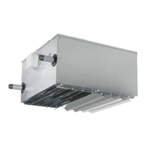
- Page 1 Operation & Maintenance Translation of the original operating instruction AIR HEATER WD-A, WD-U: For Recirculating Air, Mixed Air, Outside Air for Wall and Ceiling Installation...
- Page 2 AIR HEATER WD-A, WD-U Certificates Quality Assurance Declaration of incorporation Declaration of conformity...
-
Page 3: Table Of Contents
AIR HEATER WD-A, WD-U Content Content 1. Notes and regulations for the operator ........4 2. -
Page 4: Notes And Regulations For The Operator
Meeting and Exhibition Rooms • Lounges • Industrial and Production Companies • Greenhouses • Sales Rooms, Supermarkets, Shopping Centres WD-A Units are suitable for Supply of air which is • dust-free • without pollutants • non-aggressive • not developing corrosion •... -
Page 5: Safety
AIR HEATER WD-A, WD-U Safety 3. Safety The authorized specialized staff charged with • assembly • commissioning • maintenance must be informed about the observance of these operating instructions without starting work. Non-observance of the operating instructions can endanger the persons charged with this work and can damage the machine. -
Page 6: Goods Acceptance
and pull it towards the back, so that screw is in the small slot. 3. Press washer to the WD-A-housing . 4. Tighten firmly hexagonal screw . Unit assembly with accessories without sheet brackets, ceiling suspension. -
Page 7: Roof Safeguarding
AIR HEATER WD-A, WD-U Assembly Attention: When using accessories, outside air operation is possible, so: • Provide an anti-frost thermostat at the heat exchanger. • All ducts transporting outside air must be insulated inside the building on the outside in order to avoid deposit of moisture. -
Page 8: Ventilation Valve And Emptying Cock
Therefore use motor protection louver in case of high advance temperature of the heating medium. Without motor protection louver, WD-A-machines may be operated up to an advance temperature of the heating medium of: Wall Machine Ceiling Machine without accessories 130 °C... -
Page 9: Lamellae Adjustment, Manual
AIR HEATER WD-A, WD-U Assembly 05.07 Lamellae Adjustment, manual Blow-out louver Secondary air basic version Nr. 500 WD No. 504 Blow-out louver Blow-out louver ceiling 4-directions No. 502 D rotated 90° No. 503 W usable with 500 WD 1. First bend lamella manually into the requested position. -
Page 10: Lamellae Adjustment, Automatic - Adjustment, Function
AIR HEATER WD-A, WD-U Assembly 05.09 Lamellae Adjustment, automatic – Adjustment, Function Function: The nominal temperature (5 - 40 °C) is adjusted at the outside scale. The steepness of the control curve (spread) can be adjusted inside the housing. According to the determined temperature... -
Page 11: Electrical Connections
AIR HEATER WD-A, WD-U Electrical connections 6. Electrical connections 06.01 Parallel connection of WD units Connecting the unit to the mains, electrical installation or repair work may only be carried out by qualified personnel. Qualified personnel are obliged to comply with the general accident prevention regulations (e.g. UVV in Germany) and to wear the necessary personal protective equipment. - Page 12 AIR HEATER WD-A, WD-U Electrical connections 06.02 Repair switch Motor 001 Motor 003 2 speeds 1 speeds Y - circuit: low speed Counterclockwise rotation Δ - circuit: high speed TK=Thermal contact (TOP) TK= Thermal contact (TOP) Repair switch Repair switch 9-pole 06.03 Maximum number of WD units on one switching device...
-
Page 13: Switchgear Ac
AIR HEATER WD-A, WD-U Switching Devices 7. Switchgear AC 07.01 Switchgear, 2 speeds 400 V (motor 001) Order no. 670 5-core 9-core 4-core If automatic restart after motor fault is required, insert bridge. Power supply Motor TK=Thermal contact RT=Room thermostat... - Page 14 AIR HEATER WD-A, WD-U Switching Devices 07.03 5-step switchgear, 5 speeds 400 V (motor 001) Order no. 685 / 55-56-57-58 D 5-adrig Motor M1 Power supply Back-up fuse on site FS=Frost protection thermostat RT=Room thermostat TK=Thermal contact 07.04 5-stage switchgear, 5 speeds 230 V (motor 003) Order no.
- Page 15 AIR HEATER WD-A, WD-U Switching Devices 07.05 Switchgear with servomotor 07.06 Switchgear with continuous 515 servomotor ON / OFF 517 685 / 55-58 D N L-- 685 / 55-58 D 14 12 11 685 / 52-53 E 685 / 52-53 E...
- Page 16 AIR HEATER WD-A, WD-U Switching Devices 07.09 Switchgear with EC controller 690 EC Supply line Operating signal 230V pot. Free Max. 15 fans! Option on site EC fan terminal box *Bridge release *Bridge release Temperature sensor in fan terminal box...
- Page 17 AIR HEATER WD-A, WD-U Switching Devices 07.11 Switchgear with EC controller 692 EC with damper actuator Switch On/Off If present, If present, If present, remove jumper remove jumper remove jumper Option on site Zuleitung 230V Damper actuator Damper actuator Room thermostat Clock thermostat ext.
-
Page 18: Commissioning
AIR HEATER WD-A, WD-U Commissioning 8. Commissioning 08.01 Motor connection Commissioning may only be carried out by qualified personnel. The qualified personnel are obliged to comply with the general accident prevention regulations (e.g. UVV in Germany) and to wear the necessary personal protective equip- ment. - Page 19 AIR HEATER WD-A, WD-U Commissioning 08.02 Fan connection EC with repair switch Option -Circuit diagram_1 -Circuit diagram_2 -Circuit diagram_3 -Circuit diagram_4 Condensate pump EC-Motor EC-Motor EC-Motor EC-Motor EC-Motor Circuit diagram_3: Circuit diagram_4: Fan supply line Fan fault signal Condensate pump...
- Page 20 AIR HEATER WD-A, WD-U Commissioning 08.04 Assignment of fan connection EC with repair switch Unit type Wiring diagram number Supply voltage 12 E, 13 E, 14 E 22 E, 23 E, 24 E 32 E-E, 33 E-E, 34 E-E 32 E-D, 33 E-D, 34 E-D...
-
Page 21: Maintenance
AIR HEATER WD-A, WD-U Maintenance 9. Maintenance 09.01 Warranty Our warranty is void if damage is caused by improper handling, operation and maintenance. Experience has shown that improper or inadequate maintenance causes greater damage as the products age. Consumable and wear parts are generally excluded from the warranty. Warranty claims are only possible within the applicable periods (see General Terms and Conditions). -
Page 22: Stopping Procedure, Dismantling And Elimination
AIR HEATER WD-A, WD-U Stopping Procedure, Dismantling and Elimination 10. Stopping Procedure, Dismantling and Elimination 10.01 Decommissioning Reduce the system to minimum output via the regulation/control system: • Close the fresh air damper to prevent cooling and the risk of frost. - Page 23 AIR HEATER WD-A, WD-U Stopping Procedure, Dismantling and Elimination Casing Fan, motor, protective grille (one unit) Discharge louvre Heat exchanger Rear wall 1. Switch off and lock the main switch. 2. Disconnect the electrical supply line and the electrical connection in the terminal box.
- Page 24 AIR CONDITIONING DIVISION AIR CONDITIONING The latest version of the operating and maintenance instructions can be found at: www.wolf-geisenfeld.de/downloads Phone +49 (0)8452 99-0 Mail WOLF Anlagen-Technik GmbH & Co. KG info.hlk@wolf-geisenfeld.de Münchener Str. 54 - 85290 Geisenfeld, GERMANY +49 (0)8452 99-250 www.wolf-geisenfeld.de...