Table of Contents
Advertisement
Quick Links
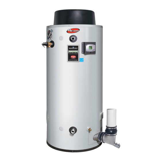
HIGH EFFICIENCY COMMERCIAL GAS WATER HEATER
INSTALLATION & OPERATION MANUAL
WITH TROUBLESHOOTING GUIDE
EF120T Model
SAVE THESE INSTRUCTIONS AND KEEP FOR FUTURE REFERENCE
WARNING
If the information in these
instructions are not followed
exactly, a fire or explosion may
result causing property damage,
personal injury, or death.
- Do NOT store or use gasoline or other
flammable vapors and liquids in the
vicinity of this or any other appliance.
- WHAT TO DO IF YOU SMELL GAS
• Do NOT try to light any appliance.
• Do NOT touch any electrical
switch; Do NOT use any phone in
your building.
• Immediately call your gas supplier
from a neighbor's phone. Follow
the gas supplier's instructions.
• If you cannot reach your gas
supplier, call the fire department.
- For customer comfort, safety, and
convenience, it is recommended this
water heater be installed and serviced
by a plumbing professional.
238-53506-00C REV 3/20
Advertisement
Table of Contents

Related Manuals for Bradford White EF120T


Summary of Contents for Bradford White EF120T
- Page 1 HIGH EFFICIENCY COMMERCIAL GAS WATER HEATER INSTALLATION & OPERATION MANUAL WITH TROUBLESHOOTING GUIDE EF120T Model WARNING If the information in these instructions are not followed exactly, a fire or explosion may result causing property damage, personal injury, or death. - Do NOT store or use gasoline or other flammable vapors and liquids in the vicinity of this or any other appliance.
-
Page 2: Table Of Contents
SECTION I: IMPORTANT INFORMATION READ CAREFULLY This gas-fired water heater is design certified by CSA International under the American National Standard, Z21.10.3 (as indicated on the rating plate) and CAN/CGA 4.3-M (as indicated on the rating plate) available from CSA Standards Association, 5060 Spectrum Way, Mississauga, Ontario, CANADA L4W 5N6. - Page 3 DANGER DO NOT store or use gasoline or other flammable, combustible, or corrosive vapors and/or liquids in the vicinity of this or any other appliance. DO NOT install any damaged venting system components. If damage is evident then please contact the supplier where the water heater was purchased, or the manufacturer listed on the rating plate for replacement parts.
- Page 4 WARNING This water heater needs fresh air for safe operation and must be installed so there are provisions for adequate combustion and ventilation air. Insufficient air supply will cause a recirculation of combustion products resulting in contamination that may be hazardous to life. This will result in carboning or sooting of the combustion chamber, burners, and flue tubes and creates a risk of asphyxiation.
-
Page 5: Section Ii: Specifications
SECTION II: SPECIFICATIONS Figure 1 – Dimensional Layout Table 1 – Specifications DIMENSIONS (INCHES) Storage Input Floor to Floor to Floor to Floor to Capacity Floor to Floor to Model No. Rate Alt. Hot Inlet T&P Hot Outlet U.S. Height Dia. -
Page 6: Section Iii: General Information
SECTION III: GENERAL INFORMATION This water heater contains the following features: Main Power On/Off Switch The front panel of this water heater has an ON/OFF switch, which has markings to indicate whether the main power to the water heater is turned on or off. Combustion System This water heater is equipped with a self-compensating negative pressure pre-mix combustion system. - Page 7 Temperature and Pressure Relief Valve WARNING Keep clear of the combination temperature and pressure relief valve discharge line outlet. The discharge may be hot enough to cause scald injury. The water is under pressure and may splash. For protection against excessive temperatures and pressure, install temperature and pressure protective equipment required by local codes;...
- Page 8 Figure 2 – Condensate Elbow with Trap *Outlet of condensate trap must not be higher than outlet of condensate elbow Condensate Neutralization The condensate draining from the water heaters covered in this manual have PH levels between 4.3 and 5.0. Install a commercially available neutralizing kit if required by local code.
-
Page 9: Section Iv: Installation Instructions
SECTION IV: INSTALLATION INSTRUCTIONS WARNING INSTALLATION OF THIS WATER HEATER REQUIRES ABILITY EQUIVALENT TO THAT OF A LICENSED TRADESMAN IN THE FIELD INVOLVED. PLUMBING, AIR SUPPLY, VENTING, GAS SUPPLY AND ELECTRICAL WORK ARE REQUIRED. DO NOT ATTEMPT TO LIGHT ANY GAS APPLIANCE IF YOU ARE NOT CERTAIN OF THE FOLLOWING: •... - Page 10 Unpacking/Inspection 1. Inspect carefully for any signs of damage. 2. Any claims for damage or shortage in shipment must be filed immediately with the shipper and noted on the Bill of Lading. NOTICE The vent terminal that is supplied with this water heater are stored at the top in the Combustion Assembly Compartment.
- Page 11 Figure 3b – Recommended Minimum Clearances for Service Access Removing the Crate 1. Remove all banding and pry off crate sides carefully so as to not damage the water heater. 2. Carefully roll/lift the water heater from the crate base. CAUTION DO NOT drop water heater.
- Page 12 Location WARNING KEEP APPLIANCE AREA CLEAR AND FREE OF COMBUSTIBLE MATERIALS, GASOLINE, AND OTHER FLAMMABLE VAPORS AND LIQUIDS. This water heater must be located in an area where the general public does NOT have access to set temperatures. Air Requirements 1.
- Page 13 Typical Installation Illustrations CAUTION If the building cold water supply has a back-flow preventer, check valve, or water meter with check valve provisions for thermal expansion of water in the hot water system must be provided. Figure 4 – Typical Front Inlet Connection Figure 5 –...
- Page 14 Figure 7 – Typical Three Water Heater Connection Figure 8 – Typical Four Water Heater Connection Note: This drawing shows a suggested piping configuration and other devices; check with local codes and ordinances for additional requirements.
-
Page 15: Section V: Water Connections
SECTION V: WATER CONNECTIONS WARNING Failure to install and maintain a new, listed temperature and pressure relief valve will release the manufacturer from any claim which might result from excessive temperature and pressures. Hydrogen gas can be produced in an operating water heater that has not had water drawn from the tank for a long period of time (generally two weeks or more). - Page 16 Table 2 – Approximate Time/Temperature Scald Chart APPROXIMATE TIME/TEMPERATURE RELATIONSHIPS IN SCALDS 120°F (49°C) More than 5 minutes 125°F (52°C) 1½ to 2 minutes 130°F (54°C) About 30 seconds 135°F (57°C) About 10 seconds 140°F (60°C) Less than 5 seconds 145°F (63°C) Less than 3 seconds 150°F (66°C)
-
Page 17: Section Vi: Venting
Figure 10 – Typical Plumbing Schematic for Zoned Heating SECTION VI: VENTING WARNING The vent system must be properly installed. Failure to properly install the vent system could result in property damage, personal injury, or death. DO NOT install damaged venting system components. If damage is evident, contact the supplier where the water heater was purchased, or the manufacturer listed on the rating plate for replacement parts. - Page 18 NOTICE For installations in Canada, field supplied vent piping must comply with CAN/CGA B149.1 (latest edition) and be certified to the Standard for Type BH, Class II, 65°C, Gas Venting Systems, ULC S636. Components of this listed system shall not be interchanged with other vent systems or unlisted pipe/fittings. All components and specified primers and cements of the certified vent system must be from a single system manufacturer and not intermixed with other system manufacturer’s vent system parts.
- Page 19 CAUTION Check to make sure flue gases DO NOT recirculate into the air intake terminal when using direct venting. If the water heater is having service issues, flue recirculation may be a contributing factor. Even when the minimum vent terminal separation distances are followed, recirculation may still occur depending upon the location outside the building, the distance from other buildings, proximity to corners, weather conditions, wind patterns, and snow depth.
- Page 20 Venting The venting instructions must be followed to avoid poor combustion or recirculation of flue gases. Such conditions cause sooting or risks of fire and asphyxiation. This water heater can be installed as either a power direct vent system or power vent system (air from inside).
- Page 21 Figure 11a – Vent Terminal Clearances (Other than Direct Vent or Powered Direct Vent Installations) (Power Vent, exhaust only) Canadian Canadian Installations Installations Installations Installations 3 feet (91 cm) within a Clearance above Clearance to each side height 15 feet (4.6 m) grade, veranda, 12 inches 12 inches...
- Page 22 Figure 11b – Direct Vent and Powered Direct Vent Terminal Clearances (Power Direct Vent, intake and exhaust) Canadian Canadian Installations Installations Installations Installations 3 feet (91 cm) within a Clearance above Clearance to each side height 15 feet (4.6 m) grade, veranda, 12 inches 12 inches...
- Page 23 The vent system must terminate so that proper clearances are maintained as cited in local codes or the latest edition of the National Fuel Gas Code, ANSI Z223.1: 1. Do not terminate near soffit vents or crawl space or other area where condensate or vapor could create a nuisance or hazard or cause property damage.
- Page 24 Figure 12 – Typical Horizontal Power Direct Vent System Vertical Installation Vertical venting system must be supported every 5 ft (1.5 m) of vertical run and every 3 ft (.92 m) of horizontal run of vent pipe length. CAUTION Failure to properly support the vent piping with hangers and clamps may result in damage to the water heater or venting system.
- Page 25 Figure 13 – Typical Vertical Power Direct Vent System Installation (Intake and exhaust terminals may be on different outside walls Through the Wall Venting with Low Ground Clearance When venting cannot exit through the wall at a height greater than or equal to 12 in (30.5 cm) (and above expected snow level) from the ground, then the installation must be modified as shown below (see Figure 14).
- Page 26 3 inch Venting Installation IMPORTANT All of the venting connections must be leak checked with a soap and water solution upon initial start-up of the water heater. Any leaks must be repaired before continuing operation of the water heater. Top of Tank Figure 15 –...
- Page 27 Maximum Vent Length Table 3 – Power Direct Vent and Power Vent Maximum Vent Length (Combined Maximum Length for Intake and Exhaust) 120T-400-3N(A) 399,999 BTU/hr 120T-500-3N(A) 499,000 BTU/hr 3 in. Vent Pipe Power Direct Vent Power Vent Power Direct Vent Power Vent Max.
- Page 28 Power Vent Installation Power venting is where the indoor air is used, and the exhaust is vented to the outside. Venting may be run horizontally through an outside wall or vertically through a roof through using either 4 in (10.2 cm), 3 in (7.6 cm), or 6 in (15.2 cm) diameter pipe.
- Page 29 Vertical Installation Vertical venting must be supported every 5 ft (1.5 m) of vertical run and every 3 ft (.92 m) of horizontal run of vent pipe length. Stress levels in the pipe and fittings can be significantly increased by improper installation. If rigid pipe clamps are used to hold the pipe in place or if the pipe cannot move freely through a wall penetration, the pipe may be directly stressed, or high thermal stresses may be formed when the pipe heats up and expands.
- Page 30 Through the Wall Venting with Low Ground Clearance When venting cannot exit through the wall at a height greater than or equal to 12 in (30 cm) from the ground and 12 in (30 cm) above expected snowfall, then the installation must be modified as shown below (see Figure 18). Refer to Table 3 (page 27) for maximum venting lengths using 4 in (10.2 cm) or 6 in (15.2 cm) diameter plastic pipe.
- Page 31 Figure 19 – Multiple Intake/Exhaust Terminal Separation Distances Note: When installing multiple intake/exhaust terminals on the same wall of a building, the nearest intake terminal must be at least 5 ft (1.5 m) from the nearest exhaust terminal. Spacing requirements are the same for roof installation.
- Page 32 397021 Termination Deduct 30 ft (9.2 m) for 3” concentric terminal ONLY for the EF120T(400,500). Note: The vent length must be reduced by 30 ft (9.2 m) when using 3 in (7.6 cm) concentric terminals, for a maximum 3 in (7.6 cm) combined vent length of 100 ft (30.5 m). There is NO reduction in vent length when using 4 in (10.2 cm) concentric terminals, for a maximum 4 in (10.2 cm) combined vent length of 200 ft (61 m)
- Page 33 Vertical Installation continued- 2. Determine the best location for the termination kit. 3. Cut the recommended 6 5/8 in (16.9 cm) diameter hole for 4 in (10.2 cm) vent termination or 4 ½ in (11.5 cm) for 3 in (7.6 cm) vent termination. 4.
- Page 34 Horizontal Installation 1. Become familiar with the approved coaxial vent kits from IPEX, as shown in Table 4 and Figures 20 through 22. 2. Determine the best location for the termination kit. NOTICE Position termination where vent vapors will NOT damage plants/shrubs or air conditioning equipment. Position termination where vent vapors will NOT be adversely affected by wind condition.
- Page 35 Low Profile Side Wall Termination Kit The IPEX Low Profile side wall termination kits are fully certified for use with IPEX product only. IPEX System 636 PVC Low Profile vent kits are made from certified compound and IPEX System 1738 PVC Low Profile vent kits are made from a UL1738 certified PVC compound.
- Page 36 Figure 25 – Typical Side Wall Termination Figure 26 – Approved Installation Orientation Figure 27 – Side Wall Termination Assembly Figure 28 – Minimum Clearances: Multiple Side Wall Terminations...
- Page 37 Vent Pipe Preparation WARNING DO NOT attempt to start this water heater until vent pipe solvent fumes completely clear from the room and inside the vent piping. Vent Pipe Preparation and Joining Most failures in vent systems result from improper preparation and joining of pipe and fittings. The guidelines below must be followed when installing the venting system.
-
Page 38: Section Vii: Gas Connections
SECTION VII: GAS CONNECTIONS The gas supply lines must meet all requirements of the National Fuel Gas Code ANSI Z223.1 (Latest Edition), or in Canada CAN/CGA B149.1 Natural Gas Installation Code (Latest Edition) or CAN/CGA B149.2 Propane Installation Code (Latest Edition). 1. - Page 39 Figure 29 – Drip Leg 120T400/500 Gas Meter Size – Natural Gases Only Be sure that the gas meter has sufficient capacity to supply the full rated gas input of the water heater as well as the requirements of all other gas fired equipment supplied by the meter. If the gas meter is too small, ask the gas company to install a larger meter with adequate capacity.
-
Page 40: Section Viii: Electrical Connections
SECTION VIII: ELECTRICAL CONNECTIONS WARNING Turn OFF or disconnect the electrical power supply to the water heater before servicing. Label all wires prior to disconnection when servicing controls. Wiring errors can cause improper and dangerous operation. Verify proper operation after servicing. All electrical wiring must be installed and grounded in accordance with local codes, or in the absence of local codes, the National Electrical Code, ANSI/NFPA 70 and/or CSA C22.2 Electrical Code. -
Page 41: Section Ix: Operating Instructions
SECTION IX: OPERATING INSTRUCTIONS WARNING Water heaters are heat-producing appliances. To avoid damage or injury there must be no materials stored against the water heater or direct vent system, and proper care must be taken to avoid unnecessary contact (especially by children) with the water heater and direct vent system. UNDER NO CIRCUMSTANCES SHOULD FLAMMABLE MATERIALS, SUCH AS GASOLINE OR PAINT THINNER BE USED OR STORED IN THE VICINITY OF THIS WATER HEATER OR IN ANY LOCATION FROM WHICH FUMES COULD REACH THE WATER HEATER. - Page 42 Lighting and Shutdown Instructions Figure 31 – Lighting Instruction Label...
- Page 43 Temperature Adjustment Table 6 – Approximate Time/Temperature Scald Chart APPROXIMATE TIME/TEMPERATURE RELATIONSHIPS IN SCALDS 120°F (49°C) More than 5 minutes 125°F (52°C) 1½ to 2 minutes 130°F (54°C) About 30 seconds 135°F (57°C) About 10 seconds 140°F (60°C) Less than 5 seconds 145°F (63°C) Less than 3 seconds 150°F (66°C)
- Page 44 WARNING Hydrogen gas can be produced in an operating water heater that has not had water drawn from the tank for a long period of time (generally two weeks or more). HYDROGEN GAS IS EXTREMELY FLAMMABLE. To prevent the possibility of injury under these conditions, we recommend a hot water faucet to be open for several minutes before you use any electrical appliance which is connected to the hot water system.
- Page 45 To Increase Setpoint Temperature Step 1: Press and hold “Temperature Up” button until desired setpoint temperature appears on the display. Step 2: Press “DONE” button for new setting to take effect immediately. If the “DONE” button is not pressed, the new temperature setting will take effect in approximately 10 seconds. To Decrease Temperature Setpoint: Step 1: Press and hold “Temperature Down”...
- Page 46 Step 2: Press “DONE” button for new setting to take effect immediately. If the “DONE” button is not pressed, the new temperature setting will take effect in approximately 10 seconds. NOTICE Pressing the “NEXT” button instead of “DONE” will enter the display to show unused screens such as “Stack ----˚F, Outdoor ----˚F, % Rate (Shows percentage of full input rate for Lightoff rate), Outlet ----˚F, Inlet ----˚F, Delta T ----˚F.
-
Page 47: Section X: Maintenance
SECTION X: MAINTENANCE DANGER DO NOT attempt to repair gas valve. DO NOT attempt to repair ignition module. DO NOT attempt to repair venturi. DO NOT attempt to repair thermostat board. DO NOT attempt to repair transformer. DO NOT attempt to repair pressure switch. WARNING To avoid damage or injury, there must be no materials stored against the water heater or vent-air intake system, and proper care must be taken to avoid unnecessary contact (especially by children) with the water... - Page 48 Maintenance Schedule WARNING Water heaters are heat producing appliances. To avoid damage or injury there must be no materials stored against the water heater or vent-air intake system, and proper care must be taken to avoid unnecessary contact (especially by children) with the water heater and vent-air intake system.
- Page 49 Draining the Water Heater The water heater must be drained if it is to be shut down and exposed to freezing temperatures. Maintenance and service procedures may also require draining the water heater. 1. Turn OFF the water heater electrical disconnect switch. 2.
- Page 50 Powered Anode System These heaters are equipped with a powered anode system. The powered anode system provides corrosion protection to the tank by supplying a low voltage current to the titanium anode rods and then periodically comparing this current with the potential between the anode rod and tank wall to make corrections. The powered anode system is designed to extend the tank life without requiring anode rod replacement.
- Page 51 Temperature and Pressure Relief Valve At least twice a year, the temperature and pressure relief valve should be checked to ensure that it is in operating condition. To check the relief valve, lift the lever at the end of the valve several times. The valve should seat properly and operate freely.
-
Page 52: Section Xi: Diagnostic And Troubleshooting Guide
SECTION XI: DIAGNOSTIC AND TROUBLESHOOTING GUIDE Sequence of Operations 1. Thermostat calls for heat. 2. Combustion blower starts at a 3,000 RPM “soft” start light off. 3. Blower pre-purge period of approximately 15 seconds. 4. Ignition control board runs an internal verification safety check for approximately 15 seconds. 5. - Page 53 Accessing Diagnostic Mode on the Water Heater Display (FOR SERVICE PERSONNEL ONLY) The display has a “Diagnostic Mode” for accessing information in aiding servicing of the water heater. This procedure is for service and installation personnel only. To enter the Diagnostic Mode, follow the steps illustrated below: WARNING The following procedure is for service and installation personnel ONLY.
- Page 54 Step 4: Press lower right “Next” button. The display will flash and show the number of any Lockout codes. Note: Refer to Service Manual for information on how to clear Lockout codes. Step 5: Press lower right “Next” button. The display will show the temperature sensor reading. Step 6: Press lower right “Next”...
- Page 55 Diagnostic Error Codes and Troubleshooting Procedures Error Code Definition of Code Cause of Problem and Actions Taken to Correct • Check power supply to the water heater. • Make sure water heater is plugged in and the breaker is on. •...
- Page 56 Error Code Definition of Code Cause of Problem and Actions Taken to Correct • Check the sensor wire harness from the DHW sensor to the control module to ensure there are no loose connections or breaks in the wires. • Check the resistance reading from each of the outside wires to the DHW Sensor Fault center (common) wire.
- Page 57 Procedure for Checking Thermostat Sensor Set the thermostat above water temperature (see temperature adjustment section) and observe system through one (1) complete cycle. Make sure system operates as desired. To check the sensor, compare the resistance of the sensor wires (center wire with yellow marking to left and right black wires) as measured by an ohmmeter to the water temperature as measured by an accurate thermometer.
- Page 58 Contact your local plumbing supplier or plumbing professional for replacement parts or contact the company at the address displayed on the rating plater of the water heater. For faster and better service, please provide the part name, model, and serial number(s) of the water heater(s) when ordering parts.
- Page 59 Notes...
- Page 60 Ambler, PA For U.S. and Canada field service, contact your professional installer or local Bradford White representative. Sales/800-523-2931 Technical Support/800-334-3393 Email/techserv@bradfordwhite.com Warranty/800-531-2111 Email/warranty@bradfordwhite.com Service Parts/800-538-2020 Email/parts@bradfordwhite.com International: international@bradfordwhite.com Halton Hills, ON Sales & Technical Support /866-690-0961 905-203-0600 Fax/905-636-0666 Email Warranty/bwccwarranty@bradfordwhite.com Technical Support/bwcctech@bradfordwhite.com...