Table of Contents
Advertisement
Quick Links
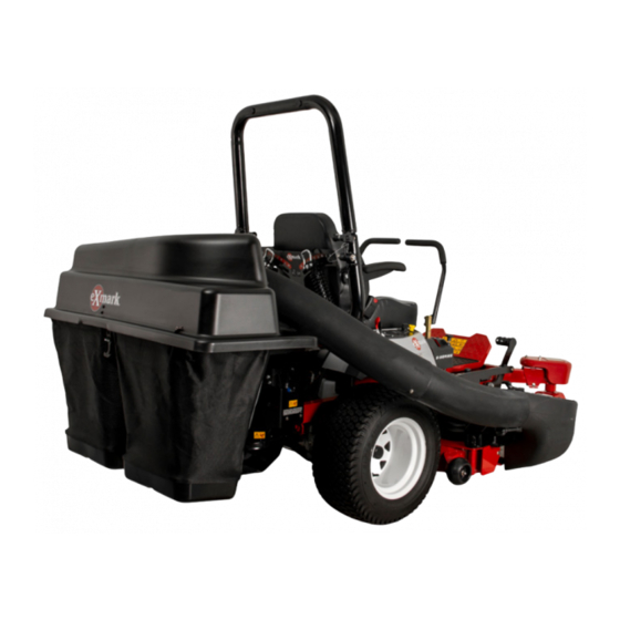
60 Inch Bagger
Quest
®
Model No. 135-0332—Serial No. 400000000 and Up
This product contains a chemical or chemicals known to the State of California
Introduction
Read this information carefully to learn how to operate
and maintain your product properly and to avoid
injury and product damage. You are responsible for
operating the product properly and safely.
Whenever you need service, genuine parts, or
additional information, contact an Authorized Service
Dealer or Customer Service and have the model
and serial numbers of your product ready.
identifies the location of the model and serial numbers
on the product. Write the numbers in the space
provided.
1. Model and serial number location
Model No.
Serial No.
© 2017—Exmark Mfg. Co., Inc.
Industrial Park Box 808
Beatrice, NE 68310
Proposition 65 Warning
to cause cancer, birth defects, or reproductive harm.
Figure 1
Figure 1
www.Exmark.com
WARNING
CALIFORNIA
This manual identifies potential hazards and has
safety messages identified by the safety-alert symbol
(Figure
2), which signals a hazard that may cause
serious injury or death if you do not follow the
recommended precautions.
1. Safety-alert symbol
This manual uses 2 words to highlight information.
Important calls attention to special mechanical
information and Note emphasizes general information
worthy of special attention.
g005673
Form No. 4503-305 Rev B
Operator's Manual
Figure 2
Original Instructions (EN)
All Rights Reserved *4503-305* B
Printed in the USA.
g000502
Advertisement
Table of Contents

Related Manuals for Exmark Quest 135-0332

Summary of Contents for Exmark Quest 135-0332
-
Page 1: Introduction
Figure 1 1. Model and serial number location Model No. Serial No. © 2017—Exmark Mfg. Co., Inc. www.Exmark.com Original Instructions (EN) All Rights Reserved *4503-305* B Industrial Park Box 808 Printed in the USA. Beatrice, NE 68310... -
Page 2: Table Of Contents
Contents Introduction ............... 1 Safety ............... 3 Towing Safety ............. 3 Safety and Instructional Decals ......4 Setup ................ 5 1 Preparing the Machine........6 2 Installing the Weight......... 6 3 Installing the Attachment Mount ....... 7 4 Installing the Latch Rod........9 5 Assembling the Bagger Top ...... -
Page 3: Safety
Safety • Keep all movement on slopes slow and gradual. Do not make sudden changes in speed, directions or turning. DANGER • The grass catcher can obstruct the view to the rear. Use extra care when operating in reverse. The engine can become hot when it is operating. -
Page 4: Safety And Instructional Decals
Safety and Instructional Decals Safety decals and instructions are easily visible to the operator and are located near any area of potential danger. Replace any decal that is damaged or missing. decal131-4036 131-4036 1. The maximum drawbar 2. Read the Operator's decal110-6691 pull is 36 kg (80 lb). -
Page 5: Setup
Setup Loose Parts Use the chart below to verify that all parts have been shipped. Procedure Description Qty. – No parts required Prepare the machine. Weight-tray Weight-tray mount, left Weight-tray mount, right Suitcase weight—16 kg (35 lb) Install the weight. Retaining rod Bolt (3/8 x 1-1/4 inches) Flange nut (3/8 inch) -
Page 6: Preparing The Machine
Note: Determine the left and right sides of the machine from the normal operating position. Installing the Weight Preparing the Machine Parts needed for this procedure: Weight-tray Weight-tray mount, left No Parts Required Weight-tray mount, right Procedure Suitcase weight—16 kg (35 lb) Retaining rod 1. -
Page 7: Installing The Attachment Mount
g196533 Figure 3 Figure 5 Cutaway view 1. Retaining rod 3. Suitcase weight 1. Weight-tray mount 3. Flange nut (3/8 inch) 2. Weight-tray 2. Bolt (3/8 x 1 inch) 4. Self-tapping bolt (5/16 x 3/4 inch) 4. Insert the retaining rod into the tray and rotate it into the locked position (Figure 2. - Page 8 g030494 g030494 Figure 6 1. Stabilizer bracket 3. Locknut (5/16 inch) g028174 Figure 8 2. Carriage bolt (5/16 x 3/4 inch) 1. Self-tapping screw (5/16 x 2. Pivot frame 3/4 inch) 2. Install the pivot frame to the machine frame as shown in Figure 7.
-
Page 9: Installing The Latch Rod
Installing the Latch Rod Parts needed for this procedure: Latch rod Hairpin cotter Procedure Install the latch rod with a hairpin cotter (Figure 11). g028306 Figure 10 Left side shown 1. Pivot frame hole 4. Support rod 2. Washer 5. Keyed slot, existing 3. -
Page 10: Installing The Bagger Top
Installing the Bagger Top Parts needed for this procedure: Grass Bag Upper bagger tube Procedure 1. Install the bagger top to the bagger frame. 2. Rotate the bagger top to align the key holes in the bagger top brackets with the keys in the posts on the bagger frame (Figure 13). -
Page 11: Installing The Chute
4. Lift the bagger top and install the bags by sliding the bag frame hooks onto the retaining brackets (Figure 14). Installing the Chute Parts needed for this procedure: Curved baffle Locknut (5/16 inch) Hand knob Washer Chute Procedure WARNING An uncovered discharge opening could allow g033032 the lawn mower to throw objects toward you... - Page 12 G013095 g013095 G013096 Figure 16 g013096 1. Deflector assembly 4. Carriage bolt (existing; Figure 17 reuse) 1. Hole in front wall of the 6. High-lift blade 2. Locknut (existing; retain) 5. Carriage bolt (existing; mower deck retain) 2. Locknut 7. Carriage bolt (existing; 3.
-
Page 13: Connecting With The Discharge Tube
G013097 Connecting with the Discharge Tube Parts needed for this procedure: Discharge tube Procedure 1. Slide the curved end of the discharge tube into the opening in the bagger top (Figure 20). G010641 g013097 Figure 18 1. Discharge chute 4. Folded metal bracket (chute) 2. -
Page 14: Operation
Operation 1. Park the machine on a level surface and disengage the blade control switch. 2. Move the motion control levers outward to the Note: Determine the left and right sides of the position, shut off the engine, EUTRAL machine from the normal operating position. remove the key, engage the parking brake and Note: Overall width of unit with bagger: 67.7 inches... -
Page 15: Clearing Obstructions From The Bagger
Removing the Bagger CAUTION Failing to remove the front bagger weights from lever steer models and operating the machine without the bagger attachment may cause an unstable condition which could result in a loss of control. • Always remove the front weights (where required) when removing the bagger attachment. -
Page 16: Transporting
Transporting Transporting the Machine Use a heavy-duty trailer or truck to transport the machine. Ensure that the trailer or truck has all necessary brakes, lighting, and marking as required g027995 Figure 25 by law. Please carefully read all the safety instructions. Knowing this information could help you, your family, 1. -
Page 17: Operating Tips
Cutting Height Do not set the mower cutting height too low because long grass surrounding the mower can prevent air from getting under the mower and entering the bagging system. If enough air doesn't get under the mower, the bagging system will plug. Cutting Frequency Cut the grass often, especially when it grows rapidly. - Page 18 at a high height of cut, then lower the mower to your normal cutting height and repeat the bagging process. Bagging Wet Grass Always try to cut grass when it is dry because your lawn will have a neat appearance. If you must cut wet grass, use the conventional side discharge feature of the mower.
-
Page 19: Maintenance
Maintenance Note: Determine the left and right sides of the machine from the normal operating position. Recommended Maintenance Schedule(s) Maintenance Service Maintenance Procedure Interval • Inspect the bagger After the first 10 hours • Clean the bagger Before each use or daily •... -
Page 20: Inspecting The Mower Blades
Inspecting the Mower Storage Blades Storing the Bagger Inspect the mower blades regularly and whenever a Attachment blade strikes a foreign object. If the blades are badly worn or damaged, install new 1. Clean the bagger attachment; refer to Cleaning blades. - Page 21 Notes:...
- Page 22 Notes:...
- Page 23 Notes:...