Table of Contents
Advertisement
Quick Links
Advertisement
Table of Contents

Related Manuals for Honeywell TR80UWD


Summary of Contents for Honeywell TR80UWD
- Page 1 TR80 WALL MODULE Installation and Operating Guide...
- Page 2 Honeywell International Inc. While this information is presented in good faith and believed to be accurate, Honeywell disclaims the implied warranties of merchantability and fitness for a purpose and makes no express warranties except as may be stated in its written agreement with and for its customer.
- Page 3 Revisions Document Firmware Published Changes Comment Version Version 09-21 1.2.1.0 08-07-21 Whole document New document TR80 - Installation and Operation Guide...
-
Page 4: Table Of Contents
TABLE OF CONTENT CHAPTER 1 - INTRODUCTION TO TR80 ............1 Introduction..............................1 Dimensions..............................2 Installing theTR80 Wall Module......................2 Before Installation ..........................2 Steps to install TR80 Wall module: ................... 3 Wiring Connections .......................... 6 Wiring Terminals.......................... 7 Powering Up the Wall Module ..................... 7 TR80 LCD Display............................. - Page 5 Adjusting The Fan Speed ........................23 Multi Speed Fans ..........................23 EC Fans ..............................24 Selecting Or Overriding Occupancy status ................24 Simple Occupied/ unoccupied selection ................24 Advanced Occupied/ unoccupied selection ..............25 Overriding the occupancy mode..................26 Selecting / Overriding HVAC mode....................26 Selecting ECO operation ........................27 Controlling Lights ..........................27 Basic on/off control ........................
- Page 6 What has changed ......................... 37 Active Display Mode ........................37 SENSORS & EXTERNAL INPUT...................... 38 Configuration............................ 38 Monitoring............................38 DO-NOT-DISTURB & MAKE-UP-ROOM ..................39 CLEANING MODE..........................39 USER INTERFACE ..........................39 Backlight Brightness........................39 LED Ring ............................. 40 Temperature display configuration ..................40 LCD Symbols.............................
- Page 7 Blind Group 1 control parameters..................55 Blind Group2 Configuration & Control Parameters ............55 DISPLAY VALUES ...........................56 Room Temperature and Humidity Override ..............56 Pre-configured Display Parameters..................56 Custom User Defined Parameter Unit..................57 Display Values Configuration ....................58 CHAPTER A - TROUBLESHOOTING ............60 CHAPTER B - CONFIGURATION PARAMETERS ........61 List of Device configuration parameters..................61 List of UI and Access configuration parameters..............63 List of HVAC Configuration Parameters..................65...
-
Page 8: Chapter 1 - Introduction To Tr80
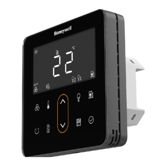
CHAPTER INTRODUCTION TO TR80 1.1 Introduction The Honeywell TR80 wall module delivers superior convenience, comfort, and energy management. Honeywell TR80 wall module includes onboard Sensors to display precise temperature and humidity measurements. It also offers an inte- grated HVAC Display, Light, and Blind controls. -
Page 9: Dimensions
1.2 Dimensions TR 80 wall module dimensions are as shown below: 18.3 mm 35.5 mm 95 mm 1.3 Installing theTR80 Wall Module 1.3.1 Before Installation 1. Read these instructions carefully. Failure to follow them could damage the product or cause a hazardous condition. 2. -
Page 10: Steps To Install Tr80 Wall Module
Caution: Electrical Shock or Equipment Damage Hazard. Can shock individuals or short equipment circuitry. Disconnect power supply before Installation. Caution: Equipment Damage Hazard. Electrostatic discharge can short equipment circuitry. Ensure that you are properly grounded before handling the unit. 1.3.2 Steps to install TR80 Wall module: 1. - Page 11 4. Pull the power cable and communication cables through the wall box. 5. Connect the wires well according to the wiring diagram. Refer to wiring details. 6. Fix the base with 2 screws to the wall box. TR80 - Installation and Operation Guide...
- Page 12 7. Attach front panel to the base. 8. Tighten the bottom screw, to fix front panel and base. 9. Switch ON the power supply to start the TR80 wall module. TR80 - Installation and Operation Guide...
-
Page 13: Wiring Connections
1.3.3 Wiring Connections Wiring diagram for 24V AC/DC and 100 - 230V AC Power Supply are shown below. Caution: Electrical Shock or Equipment Damage Hazard. Can shock individuals or short equipment circuitry. Disconnect power supply before Installation. All wiring must comply with local electrical codes and ordinances or as per below wiring connections. -
Page 14: Wiring Terminals
1.3.3.1 Wiring Terminals Terminals Number Legends Description 100 to 230 V AC, 50/60 Hz Power supply connection 24 Vac/dc ± 10% Power supply connection RS485 Port 1 Modbus RTU slave connection to controller Shared common for port1 & port 2 RS485 Port 2 Modbus RTU repeater connection to DALI64 General purpose universal input for... -
Page 15: Tr80 Lcd Display
1.4 TR80 LCD Display The LCD of TR80 wall module with all possible segments is as shown below: The following table provide an overview of all available segments of the TR80 wall module with its defined name. Name Segment Description Day symbol Night symbol Night... - Page 16 Name Segment Description Indicates displayed value is related to outdoor conditions . Indicates displayed value is relates to Outdoor Value, Indoor Value indoor (room) conditions and Set value Indicates set-point value is displayed. Fan symbol Fan speed symbol Fan and Fan speed Indicates fan speed is in auto mode Heating mode Cooling mode...
- Page 17 Name Segment Description Pascal Percentage Relative Humidity Degree Celsius Degree Fahrenheit Unit symbols Meter Cube per hour Micro gram per meter cube. Parts Per Million Parts Per Billion unit for Total Volatile Organic compound (TVOC) measurement. Carbon dioxide Total Volatile Organic compound Indoor Air Quality Parameters Particulate Matter 2.5 Particulate Matter 10...
-
Page 18: User Interface
1.5 User Interface The TR80 user interface consist of multi segment display and 10 capaci- tive touch keys. The following table provides the information of functionality associated with each key on the keypad. Key symbol Name Description Fan key Used to change the fan speed and mode. Temperature key Short press to change temp. -
Page 19: Led Ring Behavior
1.5.1 LED Ring Behavior The LED ring color changes according to the active HVAC mode in the controller. The installer can configure the LED ring behavior as per the controller programing. The LED ring color and indicated mode for typical application is as shown in below table. -
Page 20: Specification
1.6 Specification Weight and Dimensions Dimension L 95mm X W 95mm X D 54mm Weight 256 grams Minimum depth of wall box 47 mm Display Display Type Custom multi-segment LCD 72 x 37 mm Buttons 10 integrated capacitive touch areas Backlight Fascia Tempered glass... -
Page 21: System Architecture
1.7 System Architecture TR 80 wall module can act as Slave or Master in the Modbus communication net- work. The various example of system architecture are as shown below: System Architecture 1( TR80 and DALI as Modbus Slave to Room controller ) In this Architecture the controller act as Modbus Master for TR80 (Modbus salve) and DALI64(Modbus salve). - Page 22 System Architecture 2 (TR80 Modbus Slave to Room controller on Port 1 and DALI as Modbus Slave to TR80 on Port 2 (Direct Light Control).) In this Architecture the controller act as Modbus Master for TR80 (Modbus salve). DALI 64(Modbus salve) is connected on Port 2 of the TR80(Modbus Master for DALI64).
- Page 23 System Architecture 3 (TR80 Modbus Slave to Room controller and DALI64 on Sylk bus connected to Room Controller) In this Architecture the controller act as Modbus Master for TR80(Modbus salve). DALI 64 is connected on Sylk port of the controller. User light commands are polled from TR80 by controller and Transmitted to DALI64 over sylk bus for execution.
- Page 24 System Architecture 4 (TR80 Modbus Slave to Room controller and conven- tional lighting on controller inputs/outputs.) In this Architecture the controller act as Modbus Master for TR80(Modbus salve) and light and switches are connected on conventional digital and analogue Inputs/outputs of the controller. User light commands are polled from TR80 by controller and executed through digital and analogue outputs of the controller.
- Page 25 The various controllers suitable for various architecture is explained below: System Architecture Room Controller Plant Controller Merlin NX, IRM NX EHNX, JACE 8000/ HAWK 8000 Merlin NX, IRM NX EHNX, JACE 8000/ HAWK 8000 PCD7.LRXX-P5 PCD1/2/3 Modbus Room Controller Supported Plant Controller TR80 - Installation and Operation Guide...
-
Page 26: Chapter 2 - Operations
CHAPTER CHAPTER OPERATIONS This chapter gives information about the operation that users can perform once the device is ready to use. 2.1 Overview of Device States TR80 Display will switch between different states with user actions, or automati- cally on predefined timeouts. Depending on the configuration, some states may be disabled entirely, or have restricted access requiring a key-combination or Pin entry. -
Page 27: Access Level
• Cleaning Long press to enter in cleaning mode. This mode prevents accidental activation of functions while wiping the glass front. • Dark Depending on configuration this state can be activated by the power key and/or on timeout. In this state everything is off (dark) on the device. 2.2 Access Level To prevent unauthorized or accidental changes to the sytem, the device has a “locked”... -
Page 28: Unlocking The Device
2.4 Unlocking The Device Once the device is activated, it may be in locked mode (display only), to prevent unauthorized access to the device. In lock mode, appears on the screen and key on the keypad are disabled. The procedure to unlock the device is as follows: 1. -
Page 29: Adjusting Temperature
• to scroll between available values. Each value will be displayed together with unit and sequence number. • To hold any parameter on display long press ok key for 2 sec. • Tap OK again to return to Operating mode. 2.5 Adjusting Temperature when the device is unlocked user can change the temperature setpoint value. -
Page 30: Adjusting The Fan Speed
2.6 Adjusting The Fan Speed to change the fan speed. The settings are slightly different depending on type of fan. Two types of fans are supported by TR80 wall module such as: • Multi-Speed Fans • EC Fans 2.6.1 Multi Speed Fans In this type of fan, display shows selected fan speed in upper display (OFF/LO/ MED/ HI), AUTO symbol and fan speed is displayed at the bottom. -
Page 31: Ec Fans
2.6.2 EC Fans In this type of fan setting, display shows FAN in upper display and fan speed along with unit in larger display. In this fan speed setting is done in terms of percentage (0 to100%). Refer the figure shown below. The procedure to do fan speed setting for Speed fan is as follows: 1. -
Page 32: Advanced Occupied/ Unoccupied Selection
2.7.2 Advanced Occupied/ unoccupied selection In this mode, occupancy status is set by the master controller by considering vari- ous factors like time schedule, motion sensor, a key-card system etc. The various possible occupancy status are indicated on the screen as shown in the below table. -
Page 33: Overriding The Occupancy Mode
Occupancy Status Description Holiday The user has overridden the automatic mode and switched the system to building protection mode temporarily. The display shows unoccupied symbol with scrolling text "Holiday for ... days" 2.7.2.1 Overriding the occupancy mode The user can override the automatically determined mode, if configuration allows. when an user override is active, the occupancy symbol is blinking. -
Page 34: Selecting Eco Operation
The procedure to change the HVAC mode is as follows: 1. Tap , to change the HVAC mode. The display shows the text and symbol indication of the currently selected mode. 2. Tap to select the HVAC mode. Note: Tap to exit this mode without saving the changes. 3. -
Page 35: Basic On/Off Control
2.10.1 Basic on/off control • The display shows the current light level as text (On / OFF). • Use { } keys or the { } key to turn the lights on/off. 2.10.2 Basic dimming control • The display shows current (or last selected) light level as percentage. •... -
Page 36: On/Off Control With Scene Selection
2.10.3 On/off control with scene selection • The display shows last activated scene number • to switch between and activate preset scenes • Use the power button to switch between OFF and last activated scene. 2.10.4 Dimming control with scene selection •... -
Page 37: Controlling Blinds
2.11 Controlling Blinds User can set slat angle, set blind position, toggle between the blinds and switch between 0% and last set value. The procedure to set the blind control is as follows: 1. Tap in Ready mode, to enter in blind control mode. The display shows current blind position in the lower display area and the cur- rent slat angle in the upper area. -
Page 38: Cleaning The Front Glass
2.13 Cleaning The Front Glass To prevent accidental key presses, the keypad can be disabled for wiping the front glass surface. The steps to be followed before cleaning the front glass is as follows: 1. Press key together for three seconds to enter cleaning mode. LCD shows make-up-room symbol blinking, lock symbol on, and a countdown in seconds. -
Page 39: Chapter 3 - Configuration Of Tr80
CHAPTER CHAPTER CONFIGURATION OF TR80 3.1 INTRODUCTION This chapter provides descriptions for all Modbus registers and configuration parameters that can be used to adopt the TR80 to specific requirements. The information is provided in tables, showing: • Modbus register type (Coil / Input / Holding) •... -
Page 40: Temporary Commissioning Mode
4. Tap , to select Parameter value, the parameter value will start blinking. Use key to change parameter value and tap OK to save It. 5. Use to go to other parameter. 6. Tap , to exit the Configuration mode. 3. -
Page 41: Device Information
3. 2. 2 Device Information Register Relative Absolute Config Name Type Range type Address Address parameter Firmware Version 0-255 Input 30002 2 x 8bits major.minor 0-255 Firmware Version 0-255 Input 30003 2 x 8bits bug.build 0-255 The Firmware version consists of four parts as detailed below. The four parts are encoded in 2 registers. -
Page 42: Communication
3.3 COMMUNICATION 3. 3. 1 Port 1 configuration The TR80 wall module is a Modbus slave on its port 1. Register Relative Absolute Config Default Name Type Range type Address Address parameter value Modbus slave Holding 2002 42003 1-247 address 0: 1200 baud 1: 2400 baud 2: 4800 baud... -
Page 43: General Monitoring Registers
3.4 GENERAL MONITORING REGISTERS 3. 4. 1 Fault Conditions Device Faults register indicates several fault conditions that may exist on the device. Register Relative Absolute Default Name Type Range type Address Address value Bit 0: (reserved) Bit 1: on-board sensor fault Bit 2: external sensor fault Bit 3: Port1 modbus loss of comms Input... -
Page 44: What Has Changed
An override cancellation occurs when a bit is set (on a change from 0 to 1). The wall module takes no action when a bit is cleared. 3. 4. 3 What has changed This register changes when the user makes any adjustment on the wall module. It can be uti- lized by a master controller to reduce comms. -
Page 45: Sensors & External Input
3.5 SENSORS & EXTERNAL INPUT 3. 5. 1 Configuration Register Relative Absolute Config Default Name Unit Range Scale type Address Address parameter value 0: NONE 1: NO contact 2: NC contact External 3: 0-10 Vdc Holding 2011 42012 sensor enum 4: 2-10 Vdc type 5: Raw Ohms... -
Page 46: Do-Not-Disturb & Make-Up-Room
3.6 DO-NOT-DISTURB & MAKE-UP-ROOM Do-not-Disturb and/ Make-Up-Room functions can be enabled individually. The button on the TR80 will be enabled only if at least one of these functions are enabled. Register Relative Absolute Config Default Name Type Range type Address Address parameter value... -
Page 47: Led Ring
3. 8. 2 LED Ring These registers can be used to determine or override the default color and behavior of the LED ring. Register Relative Absolute Config Default Name Type Range type Address Address parameter value Holding 2104 42105 Ring brightness 0-100% 100% Ring brightness... -
Page 48: Lcd Symbols
3. 8. 4 LCD Symbols Most symbols on the LCD are activated with internal logic depending on current status (occu- pancy etc). Other symbols can be only activated via Modbus by a master controller, as explained below. Register Relative Absolute Default Name Type... -
Page 49: Power Button Functions
3. 8. 6 Power button functions For the device’s READY mode, the power button can be assigned different functions Register Relative Absolute Config Default Name Type Range type Address Address parameter value 0: No function 1: Dark Mode Power Button 2: Sleep Mode Holding 2110... -
Page 50: User Access Control And Timeouts
Required master controller logic: • The master controller can become aware of the user action Lights On / Lights Off by reading the input register 102. It is important to note that this automatically returns to 0 when the master reads it. There is no need for the master controller to reset it. •... -
Page 51: Hvac
Timeout to dark mode : If device is in sleep mode and no buttons are touched for this period, the device will enter dark mode turning off the display, all buttons and LED ring. If set to 0, it will immediately enter dark mode on sleep mode timeout (see above). -
Page 52: Fan Speed Control
3. 9. 2 Fan Speed Control Register Relative Absolute Config Default Name Type Range type Address Address parameter value 0: no fan 1: Single speed fan Holding 2204 42205 Fan type enum 2: 2-speed fan 3: 3-speed fan 4: EC fan 0: 1% 1: 2% EC Fan speed... -
Page 53: Hvac Mode Selection
3. 9. 3 HVAC mode selection TR80 allows two different Hvac mode selection options: simple or advanced. In simple mode, the occupancy button simply and directly switches between available modes (heat- ing/cooling/fan-only…) similarly to a basic A/C unit. Applications that have more complicated requirements (for example having two different cooling systems within the same room) can use the advanced mode. ... -
Page 54: Occupancy
• Bits 0..2: • 000 (0): heat & cool not available (grey ring) • 001 (1): Cooling mode (blue ring) • 010 (2): Heating mode (orange ring) • 011 (3): Heating+cooling (purple ring) • 100 (4): Fan-only (green ring) • 101 (5): Alarm (red ring) •... -
Page 55: Occupancy Control
2. Modbus only: With this setting, the occupancy button on the wall module is disabled. Master controller determines the occupancy mode. 3. Modbus with override from button: In this case, the master controller determines the occupancy mode based on a time schedule, presence detector and/or other inputs. However, the user may be allowed to override the current mode using the occupancy button.This allows user to select further modes such as holiday or bypass. -
Page 56: Holiday & Bypass Overrides
3. 10. 3 Holiday & Bypass overrides When the user activates Holiday override, the system will remain off (or in building protection mode) until the set time (number of days) expires. When the user activates Bypass override, the system will remain in comfort mode until the set time (number of minutes) expires. -
Page 57: Auto-Reset Of Occupancy Override
3. 10. 5 Auto-reset of occupancy override The TR80 can be configured to automatically cancel a user occupancy override when the master occupancy mode changes (holding register 1500, refer Occupancy control). Register Relative Absolute Config Default Name Unit Range type Address Address parameter... -
Page 58: Light Group 1 Configuration
3. 11. 1 Light Group 1 configuration Register Relative Absolute Config Default Name Unit Range type Address Address Parameter value 0: only on/off Light Group 1 Holding 2302 42303 enum control allow dimming 1: allow dimming Light Group 1 min Holding 2303 42304... -
Page 59: Light Group 2 Configuration & Control
3. 11. 3 Light Group 2 configuration & control The configuration parameter for group 2 are explained in below table. Refer lighting group1 for explanation. Register Relative Absolute Config Default Name Unit Range type Address Address Parameter value 0: only on/off Light Group 2 Holding 2306... -
Page 60: Light Group 4 Configuration & Control
3. 11. 5 Light Group 4 configuration & control The group 3 configuration parameters are explained in below table. Refer lighting group1 for explanation. Register Relative Absolute Config Default Name Unit Range type Address Address Parameter value 0: only on/off Light Group 4 Holding 2314... -
Page 61: Blinds Control
3.12 BLINDS CONTROL TR80 can control up to 2 blinds, curtains or shutters. General blind parameters are as shown below. Register Relative Absolute Config Default Name Unit Range type Address Address parameter value Holding 2400 42401 Blind Group Count 0…2 0: 1% 1: 2% Blind position... -
Page 62: Blind Group 1 Control Parameters
3. 12. 2 Blind Group 1 control parameters Register Relative Absolute Default Name Unit Range type Address Address value Holding 1400 41401 Blind 1 position feedback 0-100% Holding 1401 41402 Blind 1 angle feedback ° -180…+180° Input 30401 Blind 1 new position 0-100% 32767 Input... -
Page 63: Display Values
3.13 DISPLAY VALUES In addition to the operationally required ones, TR80 can display several additional values for user information. The master makes these values available to the wall module by writ- ing to relevant registers. For these registers, the default value is 32767 (hex 7FFF) representing an invalid value. Any of these registers with the invalid value will be ignored by the wall module. -
Page 64: Custom User Defined Parameter Unit
3. 13. 3 Custom User Defined Parameter Unit A text, up to 4 characters long, can be displayed in the upper screen area. This custom text is configured with two registers, each character encoded as 8-bits. Only A-Z uppercase chars, numbers, minus-sign, slash (/) and space are supported. -
Page 65: Display Values Configuration
0111 (224) : mg/m3 1000 (256) : ug/m3 1001 (288) : ppm 1010 (320) : ppb Bits 11..9: air quality icons 000 (0): none 001 (512): CO2 010 (1024): TVOC 011 (1536): PM2.5 100 (2048): PM10 Bit 13..12: Value alignment 00 (0) : right align;... - Page 66 9: Outdoor Humidity 10: Indoor PM2.5 11: INDOOR_PM_10 12: Outdoor PM 2.5 13: Outdoor PM10 14: Energy in kw 15: Energy in kwh 16: Room Number 17: HVAC Override Status 18: Reserved1 19: Reserved2 20: Reserved3 21: Reserved4 22: Custom parameter 1 23: Custom parameter 2 24: Reserved5 25: Reserved6...
-
Page 67: Chapter A - Troubleshooting
APPENDIX TROUBLESHOOTING The fault condition is displayed on screen along with alarm symbol. Press OK but- ton in ready mode then, up/down buttons to cycle the display between several val- ues. The fault condition will be displayed as an error code. Refer the troubleshooting table listed below to understand the error codes, it’s meaning and action to be per- formed to resolve the error. -
Page 68: Chapter B - Configuration Parameters
APPENDIX CONFIGURATION PARAMETERS List of Device configuration parameters Config Type/ Range parameter Name Default Notes Unit (min-Max) number Firmware Version1 2 bytes 0-255 Firmware version: major, minor 0-255 Firmware Version2 2 bytes 0-255 Firmware version: bug, biult 0-255 ConfigId 0-65535 ConfigDateCode 2 bytes 0-65535... - Page 69 Config Type/ Range parameter Name Default Notes Unit (min-Max) number External sensor enum "0: NONE NO : 0=open, 1 = closed type 1: NO contact NC : 0= closed, 1 = open 2: NC contact 3: 0-10 Vdc 4: 2-10 Vdc 5: Raw Ohms 6: NTC10K 7: NTC20K"...
-
Page 70: List Of Ui And Access Configuration Parameters
List of UI and Access configuration parameters Config Type/ Range parameter Name Default Notes Unit (min-Max) number Room Number 0-9999 (or undefined 0x7FFF = 0x7FFF) LCD Backlight 0…100% 100% brightness Ring brightness 0…100% 100% SLEEP mode ring 0…100% 100% brightness Room temperature enum 0: don't display room... - Page 71 Config Type/ Range parameter Name Default Notes Unit (min-Max) number User access enum 0 free: no restriction, 0: free Restrict user access to protection no timeout lock temperature, lights 1 simple: require key combination to unlock 2 secure: require pass-key to unlock 3 no access: display only, no control allowed...
-
Page 72: List Of Hvac Configuration Parameters
List of HVAC Configuration Parameters Config Type/ Range parameter Name Default Notes Unit (min-Max) number Setpoint enum 0: absolute 0: absolute style 1: relative Setpoint signed int absolute mode: -50….+150 absolute: 10 °C minimum (°C / K) relative mode: -15…….0 relative: -5 K Setpoint signed int... -
Page 73: List Of Lighting Configuration Parameters
Config Type/ Range parameter Name Default Notes Unit (min-Max) number AvailableHv enum Bit0: "AUTO" Default : Auto/Heat/Cool/Fan acModes Bit1: "HEAT" Bit2: "COOL" Bit3: "FAN" Bit4: "OFF" Bit5: "HTG1" Bit6: "HTG2" Bit7: "CLG1" Bit8: "CLG2" List of Lighting Configuration Parameters Config Type/ Range Defau... - Page 74 Config Type/ Range Defau parameter Name Notes Unit (min-Max) number Light Group 3 max 0…100% 100% level Light Group 3 Max 0-16 0 = scene selection disabled Scene No Light Group 4 type enum 0: on-off / 1: dimmable Light Group 4 min 0…100% level Light Group 4 max...
-
Page 75: List Of Blinds Configuration Parameters
List of Blinds configuration Parameters Config Range parameter Name Type/ Unit Default Notes (min-Max) number Blind Group Count 0…2 Blinds position adjust enum 0: 1% step size 1 : 2% 2 : 5% 3: 10% 4: 20% Blinds angle adjust enum 0: 1% step size... -
Page 76: List Of Occupancy Configuration Parameters
List of Occupancy configuration Parameters Config Type/ Range parameter Name Default Notes Unit (min-Max) number Occupancy enum 0: Modbus only 0: Modbus only Source 1: Button only (button disabled) 2: Modbus & override from 1: Button only (simple button mode, no override, only occupied/ unoccupied switching on WM) -
Page 77: List Of Display Values Configuration Parameters
Config Type/ Range parameter Name Default Notes Unit (min-Max) number Occupancy bitmap Bit0: When master mode Auto Reset changes to UNOCC, cancel (0x37) UNOCC override (11 1111) Bit1: When master mode changes to UNOCC, cancel STBY override Bit2 : When master mode changes to UNOCC, cancel OCC override Bit3: reserved... - Page 78 Honeywell Building Technologies 1985 Douglas Drive North Golden Valley, MN 55422 customer.honeywell.com Honeywell Building Control ™ 31-00482M-01 09/21...