Table of Contents
Advertisement
Quick Links
Advertisement
Table of Contents

Related Manuals for ABB Baldor BC145


Summary of Contents for ABB Baldor BC145
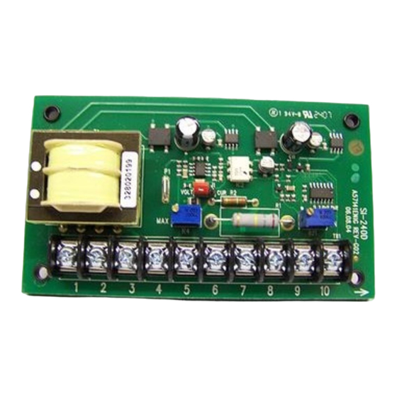
- Page 1 BC145 SIGNAL ISOLATOR BOARD Installation & Operating Manual 4/17 MN1373...
- Page 2 Any trademarks used in this manual are the property of their respective owners. Important: Be sure to check www.baldor.com to download the latest version of this manual in Adobe Acrobat PDF format.
-
Page 3: Table Of Contents
Table of Contents Chapter 1 Introduction Safety Warning ................1-1 General Performance Specifications . -
Page 4: Introduction
Chapter 1 Introduction Introduction The BC145 Signal Isolator is used to isolate, amplify and condition DC voltage and current signals from any source (motors, tachs and transducers) which will provide most adjustable speed motor controls with a voltage following input. The maximum output voltage of the isolator is 10 volts which is a linear function of the input signal. - Page 5 SAFETY NOTICE Continued WARNING: Electrical shock can cause serious or fatal injury. Be sure that all power is disconnected and there is no voltage present from this equipment or equipment to which it is or will be connected. Electrical shock can cause serious or fatal injury. Only qualified personnel should attempt the installation and start-up procedures.
- Page 6 SAFETY NOTICE Continued Caution: Do not connect AC power to the Motor terminals A1 and A2. Connecting AC power to these terminals may damage the control. Caution: Baldor recommends not to use Grounded Leg Delta transformer power leads that may create ground loops. Instead, we recommend using a four wire Wye.
-
Page 7: General Performance Specifications
Table 1-1 General Performance Specifications Description Specification AC Power Requirements 115 or 208-230VAC, 50/60Hz (1) Signal Input Voltage 0-25, 0-120, 0-550VDC Signal Input Current 1-5, 4-20, 10-50mA (3) Maximum Output Voltage 10 volts Maximum Output Current 10mA Range of “MIN” Trimpot ±3 volts Range of “MAX”... -
Page 8: Installation
Chapter 2 Installation Mounting Instructions Mount the Signal Isolator using (4) 6-32 screws (not included). Use the Control Layout and Mechanical Specifications drawing to locate the mounting holes. The unit is designed to be mounted in any position providing its components do not come in contact with grounded or live wiring. -
Page 9: Wiring
Chapter 3 Installation Wiring WARNING: READ SAFETY WARNINGS BEFORE ATTEMPTING TO USE THIS CONTROL. Caution: To avoid erratic operation, do not bundle AC Line and motor wires with potentiometer, voltage following, enable, inhibit or other signal wiring. Use shielded cables on all signal wiring over 12” (30cm). The shield should be earth grounded on the control side only. -
Page 10: Input Terminals
3-2 230V Connection Input Terminals A voltage or current signal from a microprocessor, tachometer, transducer, etc. is to be connected to terminals “5” through “8”. The selection of the proper terminal is based on the maximum level of the input signal. See Figure 3-3, Table 3-1 and Figure 3-4. - Page 11 Figure 3-3 Current Signal Input Connection 4-20mA DC Signal Input: No resistor required. Set Jumper J1 in “CUR” position. 10-50mA DC Signal Input (Use Large Resistor with Color Code “Brown-Green-Brown”): Install the 150Ω - 1W resistor across Terminals “5” and “6”. Set Jumper J1 in“CUR” position. 1-5mA DC Signal Input (Use Small Resistor with Color Code “Brown-Black-Red”): Install the 1kΩ...
-
Page 12: Voltage Signal Input
Voltage Signal Input WARNING: READ SAFETY WARNINGS BEFORE ATTEMPTING TO USE THIS CONTROL. Note: The Voltage/Current (VLT/CUR) jumper must be in the VLT position (factory setting). The BC145 is designed to accept a wide range of input voltage signals as follows: 3-1 Voltage Input Signal Minimum Input Maximum Input... - Page 13 Figure 3-4 Voltage Input Signal Connections a. Connect the armature of the leader motor to the BC145 input terminals “5” (-) and “7” (+). b. Set the armature voltage of the leader motor to zero (0). Adjust the “MIN” trimpot so that the output at terminals “9” (-) and “10” (+) reads zero (0) volts.
-
Page 14: Adjustments
Chapter 4 Adjustments Output Signal WARNING: THE CONTROLS ENABLE CIRCUIT IS INOPERATIVE WHEN USING THE BC145 SIGNAL ISOLATOR CONNECTED AS SHOWN IN THE FOLLOWING DIAGRAMS. The output signal from the BC145 is obtained from terminals “9” (-) and “10” (+). Connect the output directly to the signal following input terminal of the speed control. - Page 15 Note: * The BC141 controls depicted above and in the following diagrams could also be other models in your application - BC142, BC142-5, BC142-6, or BC155. A 10K ratio potentiometer is used to control up to ten (10) follower motors. If a 5K ratio potentiometer is used, up to five (5) follower motors can be controlled.
- Page 16 Figure 4-3 Process Control with Auto/Manual Switch - Connection for Models BC141, BC142, BC142-5, BC142-6, and BC155 Note: The BC145 can be wired in an Auto/ Manual mode which will allow manual override of an automatic process. See Figure 4-3. Figure 4-4 Process Control with Auto/Manual Switch - Connection for Models BC154, BC154-SI, BC154-R, BCWD140, BC160, and BC354 MN1373...
- Page 17 Figure 4-5 Process Control with Auto (Ratio Pot)/Manual Switch - Connection for Models BC141, BC142, BC142-5, BC142-6 and BC155 Note: The following circuit provides for dual purpose usage of the speed pot. In the “AUTO” mode it is used for the ratio control and in the “MAN” mode it is used for manual speed adjustment.
- Page 18 LIMITED WARRANTY For a period of 2 years from date of original purchase, BALDOR will repair or replace without charge controls which our examination proves to be defective in material or workmanship. This warranty is valid if the unit has not been tampered with by unauthorized persons, misused, abused, or improperly installed and has been used in accordance with the instructions and/ or ratings supplied.
- Page 20 Baldor Electric Company P.O. Box 2400, Fort Smith, AR 72902-2400 U.S.A., Ph: (1) 479.646.4711, Fax (1) 479.648.5792, International Fax (1) 479.648.5895 www.baldor.com © Baldor Electric Company All Rights Reserved. MN1373 (A42086) - Rev F - 04/17...