Table of Contents
Advertisement
Quick Links
® ®
HYPRO
ARAG
®
Foam Marker
Operating Instructions and Parts Manual
A Complete Kit for Turf and Row-Crop Sprayers
Description
Features & Benefits:
• Save money and increase efficiency by avoiding
costly misses and overlaps while spraying
• No premixing required; foam is made in the drop
assembly at the end of the boom
• Fits any crop sprayer, turf sprayer or seeding
machine (extra hose required for booms longer than
60 feet - part # 520000-751)
• Electro-pneumatically operated, requiring a 12-volt
DC 6 Amp power supply
• 108' dual liquid/air hose with thermoformed
polystyrene covering for UV protection
Form L-1475
Rev. B
Part # 520004
Advertisement
Table of Contents

Summary of Contents for Pentair Hypro ARAG 520005
- Page 1 Form L-1475 ® ® HYPRO Rev. B ARAG ® Foam Marker Operating Instructions and Parts Manual Description A Complete Kit for Turf and Row-Crop Sprayers Part # 520004 Features & Benefits: • Save money and increase efficiency by avoiding costly misses and overlaps while spraying •...
- Page 2 Warning! California Proposition 65 Warning -- This product and related accessories contain chemicals known to the State of California to cause cancer, birth defects or other reproductive harm. Read the instructions in this manual carefully. Hypro/ARAG cannot be held responsible for damage caused by improper use or installation.
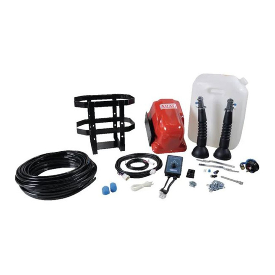
- Page 3 Foam Marker Kit Contains: I NG I NG D IR D IR IO N IO N 1. Complete tank cap assembly 2. Compressor mounting frame 3. Tank bottom support 4. 5-gallon tank 5. Complete compressor unit 6. Nozzle drop assembly 7.
-
Page 4: Overall Dimensions
Technical and Operating Specifications Description Value Power supply voltage ......12 Vdc Current draw (at 12 Vdc) ..... .9 A Working temperature . -
Page 5: System Installation
System Installation Installing the foam marker on a sprayer Foam Marker Installation Precautions: When installing the foam marker, it is necessary to observe a few essential rules. • Secure the electric compressor unit in a position sheltered from stones picked up by the wheels or by the products sprayed from the booms. - Page 6 Mounting the Electric Compressor and Tank The electric compressor and tank can be mounted on the machine in two different ways (see illustration at left). Option 1 When joining the electric compressor unit “D” to the foaming liquid tank “A,” place the spacers “B” and fixing bracket “C”...
-
Page 7: Mounting The Control Unit
Mounting the Liquid/Air Circuit Connect the white hoses (air) and the dark blue hoses (liquid) to the mixing sprayer farthest from the electric compressor unit, making sure the hoses and fittings are the same color. Lay the hoses along the framework of the boom as far as the electric compressor unit, allowing extra by the hinges. -
Page 8: Final Testing
Final Testing 1. Put some liquid in the tank. 2. Fully screw the cap onto the tank. 3. Start the electric compressor positioning the selector (“A” on illustration below) on the right. 4. After a few seconds, check that the liquid is coming out of the right-hand foam nozzle. -
Page 9: Foam Marker Operation
Foam Marker Operation Preliminary Checks Starting and Operation After a long period of inactivity, it is recommended to • Start up the compressor with the lever selector A, on check the tightness of the seal fittings. the control panel. After a few seconds, the circuit will reach its working pressure, making foam come out of Preparation and Solution the selected foam nozzle. - Page 10 Maintenance (Continued) Machine down for up to seven days For periods of inactivity of up to seven days, carry out the following operations: • Slacken the band “B” and remove the diffusor “A.” • Remove the grid “C” by turning it counterclockwise. •...
- Page 11 Maintenance (Continued) Periodical Cleaning Machine down for longer than 30 days For long periods of inactivity, proceed as follows: • Carry out the operations described in the “Machine down for up to 30 days” section. • Clean the electric compressor unit: 1.
-
Page 12: Parts Included
Parts Included - 12 -... -
Page 13: Parts Breakdown
Parts Breakdown FOAM MARKER PART NUMBER 520004-262 520004-263 - 13 -... - Page 14 Parts Breakdown Complete Compressor Assembly No. 520004-060 (Discontinued) 2 pcs. - 14 -...
- Page 15 Parts Breakdown - 15 -...
-
Page 16: Troubleshooting
Troubleshooting PROBLEM CAUSE REMEDY The electric compressor will not - No power reaches the - Check the fuse. work. The pilot lights fail to come on. console. - Check the electrical connections of the console. The electric compressor will not - Electrical connection between - Check the connections between the work. - Page 17 — NOTES — - 17 -...
- Page 18 — NOTES — - 18 -...
- Page 19 — NOTES — - 19 -...
-
Page 20: Return Procedures
Hypro may request additional information, and may require a sketch to illustrate the problem. Contact the factory to receive a return material authorization before sending the product. All products returned for warranty work should be sent shipping charges prepaid to: HYPRO / PENTAIR Attention: Service Department...