Table of Contents
Advertisement
Quick Links
Advertisement
Table of Contents

Related Manuals for Elation SEVEN BATTEN 72


Summary of Contents for Elation SEVEN BATTEN 72
- Page 1 SEVEN BATTEN 72 User Manual...
- Page 2 Elation Professional B.V. | Junostraat 2 | 6468 EW Kerkrade, The Netherlands +31 45 546 85 66 | +31 45 546 85 96 fax | www.elationlighting.eu | info@elationlighting.eu Elation Professional Mexico | AV Santa Ana 30 | Parque Industrial Lerma, Lerma, Mexico 52000 +52 (728) 282-7070 DOCUMENT VERSION Due to additional product features and/or enhancements, an updated version of this document may be available online.
-
Page 3: Table Of Contents
CONTENTS General Information Limited Warranty Safety Guidelines Maintenance Guidelines Fixture Overview Installation Guidelines Remote Device Management (RDM) Control Panel System Menu (Software Version 1.04) System Menu (Software Version 1.09) Pixel Zones DMX Traits (Software Version 1.04) DMX Traits (Software Version 1.09, RGB Modes) DMX Traits (Software Version 1.09, HSI Modes) Specifications Dimensional Drawings... -
Page 4: General Information
Please recycle whenever possible. BOX CONTENTS Power Cable CUSTOMER SUPPORT Contact ELATION Service for any product related service and support needs. forums.elationlighting.com Also visit with questions, comments or suggestions. ELATION SERVICE USA - Monday - Friday 8:00am to 4:30pm PST 323-582-3322 | Fax 323-832-9142 | support@elationlighting.com... -
Page 5: Limited Warranty
The sole responsibility of Elation Professional under this warranty shall be limited to the repair of the product, or replacement thereof, including parts, at the sole discretion of Elation Professional. All products covered by this warranty were manufactured after January 1, 1990, and bare identifying marks to that effect. -
Page 6: Safety Guidelines
This fixture is a sophisticated piece of electronic equipment. To guarantee a smooth operation, it is important to follow all instructions and guidelines in this manual. Elation Professional is not respon- sible for injury and/or damages resulting from the misuse of this fixture due to the disregard of the information printed in this manual. - Page 7 SAFETY GUIDELINES RISK GROUP 3 - RISK OF EXPOSURE TO ULTRAVIOLET UV RADIATION! FIXTURE EMITS HIGH INTENSITY WAVELENGTH OF ULTRAVIOLET UV LIGHT FROM THE UV LED. WEAR PROPER EYE AND SKIN PROTECTION. AVOID PROLONGED PERIODS OF EXPOSURE TO UV LED. AVOID WEARING WHITE COLOR CLOTHING AND/OR USING UV PAINTS ON SKIN.
-
Page 8: Maintenance Guidelines
Regular inspections are recommended to ensure proper function and extended life. There are no user serviceable parts inside this fixture, please refer all other service issues to an authorized Elation service technician. Should you need any spare parts, please order genuine parts from your local Elation dealer. -
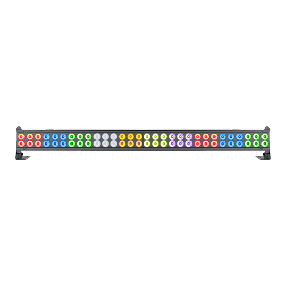
Page 9: Fixture Overview
FIXTURE OVERVIEW... -
Page 10: Installation Guidelines
INSTALLATION GUIDELINES FLAMMABLE MATERIAL WARNING Keep fixture minimum 5.0 feet (1.5m) away from flammable materials and/or pyrotech- nics. ELECTRICAL CONNECTIONS A qualified electrician should be used for all electrical connections and/or installations. USE CAUTION WHEN POWER LINKING OTHER MODEL FIXTURES AS THE POWER CONSUMPTION OF OTHER MODEL FIXTURES MAY EXCEED THE MAX POWER OUTPUT ON THIS FIXTURE. - Page 11 INSTALLATION GUIDELINES CLAMP MOUNTING The fixture includes adjustable mounting brackets on both ends, which include 3-position holes for versatile fixture positioning. When mounting this fixture to truss or a metal structure, be sure to secure an appropriately rated clamp (not included) to both brackets using M10 screws. Depending on the rigging position of the fixture, it may be best to use more than one clamp attached to the mounting brackets and more than one safety cable.
- Page 12 INSTALLATION GUIDELINES KLING-NET / ART-NET CONNECTION When connecting the fixture to a network switch to control multiple devices, a Gigabit Ethernet Switch that supports IGMP (Internet Group Management Protocol) is required. Using a Gigabit Eth- ernet Switch that does not support IGMP can cause erratic behavior of all devices that have been connected to the switch.
-
Page 13: Remote Device Management (Rdm)
REMOTE DEVICE MANAGEMENT (RDM) NOTE: In order for RDM to work properly, RDM enabled equipment must be used throughout the entire system, including DMX data splitters and wireless systems. Remote Device Management (RDM) is a protocol that sits on top of the DMX512 data standard for lighting, and allows the DMX systems of the fixtures to be modified and monitored remotely. -
Page 14: Control Panel
CONTROL PANEL The fixture includes an easy to navigate system menu where fixture settings can be adjusted via the LCD control panel located on the back of the fixture (see image below). During normal operation, pressing the MODE button once will access the main menu. Navigate through the various sub- menus by pressing the UP and DOWN buttons. -
Page 15: System Menu (Software Version 1.04)
SYSTEM MENU (SOFTWARE VER 1.04) MENU SUB MENU OPTIONS / VALUES DESCRIPTION 001 - xxx Address Set ADDR DMX Address Setting RGB 3-Ch RGBSeven 3-Ch 8bit 7-Ch 16bit 14-Ch Master 15-Ch Mode DMX Channel / User Mode Cells 70-Ch MastCell 78-Ch HSI 4-Ch HSI Mast 10-Ch HSI Cell 38-Ch... - Page 16 SYSTEM MENU (SOFTWARE VER 1.04) MENU SUB-MENU OPTIONS / VALUES DESCRIPTION 900 Hz, 1000 Hz, 1100 Hz, 1200 Hz, 1300 Hz, Frequen Set LED refresh frequency 1400 Hz, 1500 Hz, 2500 Hz, 4000 Hz, 5000 Hz, 10 KHz, 15 KHz, 20 KHz, 25 KHz 001 - 256 Universe Enter fixture universe...
-
Page 17: System Menu (Software Version 1.09)
SYSTEM MENU (SOFTWARE VER 1.09) MENU SUB MENU OPTIONS / VALUES DESCRIPTION 001 - xxx Address Set ADDR DMX Address Setting RGB 3-Ch RGBSeven 3-Ch 8bit 7-Ch 16bit 14-Ch 16b+ Dim 16-Ch Extended 15-Ch Mode DMX Channel / User Mode Cells 70-Ch Cells Dim7 2-Ch Exte Cells 78-Ch... - Page 18 SYSTEM MENU (SOFTWARE VER 1.09) MENU SUB-MENU OPTIONS / VALUES DESCRIPTION 1.0s 1.5s 2.0s 3.0s 4.0s Dim Mode (con- 5.0s Set Dimmer Curve Mode tinued) 6.0s 7.0s 8.0s 9.0s 10.0s Disp Set ADDR, Disp Ch Select default display Auto Fan Set Set fan speed High Linear...
- Page 19 SYSTEM MENU (SOFTWARE VER 1.09) MENU SUB-MENU OPTIONS / VALUES DESCRIPTION Set program speed, 1 is slowest and 99 1 - 99 Speed is fastest Strobe 000 - 255 Select Static color and static/ strobe Static R, G, B, RG, GB, value RB, RGB, Black Select 15 color program + shutter/...
-
Page 20: Pixel Zones
PIXEL ZONES The Flip mode can be selected from the system menu, which flips the starting PIXEL ZONE location and sequence from one end of the batten to the opposite end. This feature makes it easy to config- ure the pixel zones of multiple battens to be the same regardless of their installation orientation. See diagram below. -
Page 21: Dmx Traits (Software Version 1.04)
DMX TRAITS (SOFTWARE VER 1.04) CHANNEL Mast FUNCTION 8bit 16bit Master Cells VALUES Seven Cell Mast Cell 14CH 15CH 70CH 78CH 10CH 38CH Shutter / Strobe 000 - 031 LED Off 032 - 063 LED On 064 - 095 Strobe Effect, slow to fast 096 - 127 LED On Strobe Pulse Effect, slow 128 - 159... - Page 22 DMX TRAITS (SOFTWARE VER 1.04) CHANNEL Mast FUNCTION 8bit 16bit Master Cells VALUES Seven Cell Mast Cell 14CH 15CH 70CH 78 CH 10CH 38CH Program Macro Speed, 000 - 255 slow to fast Program Macro Fade, 000 - 255 slow to fast Color Macros 001 - 004 Color Macro 01 005 - 008 Color Macro 02...
- Page 23 DMX TRAITS (SOFTWARE VER 1.04) CHANNEL Mast FUNCTION 8Bit 16Bit Master Cells VALUES Seven Cell Mast Cell 14CH 15CH 70CH 78CH 10CH 38CH Color Macros (contin- ued) 121 - 124 Color Macro 31 125 - 128 Color Macro 32 129 - 132 Color Macro 33 133 -136 Color Macro 34 137 - 140 Color Macro 35 141 - 144 Color Macro 36...
- Page 24 DMX TRAITS (SOFTWARE VER 1.04) CHANNELS Mast FUNCTION 8Bit 16Bit Master Cells VALUES Seven Cell Mast Cell 14CH 15CH 70CH 78CH 10CH 38CH Color Macros (contin- ued) 249 - 252 Color Macro 63 253 - 255 Color Macro 64 Hue, All Pixels/Zones, 000 - 255 0% to 100% Saturation, All Pixels/...
- Page 25 DMX TRAITS (SOFTWARE VER 1.04) CHANNELS Mast FUNCTION 8Bit 16Bit Master Cells VALUES Seven Cell Mast Cell 14CH 15CH 70CH 78CH 10CH 38CH Intensity, Zone 1, 0% to 000 - 255 100% Red, Zone 1, 0% to 000 - 255 100% Green, Zone 1, 0% to 000 - 255...
- Page 26 DMX TRAITS (SOFTWARE VER 1.04) CHANNELS Mast FUNCTIONS 8Bit 16Bit Master Cells VALUES Seven Cell Mast Cell 14CH 15CH 70CH 78CH 10CH 38CH Red, Zone 3, 0% to 000 - 255 100% Green, Zone 3, 0% to 000 - 255 100% Blue, Zone 3, 0% to 000 - 255...
- Page 27 DMX TRAITS (SOFTWARE VER 1.04) CHANNELS Mast FUNCTIONS 8Bit 16Bit Master Cells VALUES Seven Cell Mast Cell 14CH 15CH 70CH 78CH 10CH 38CH Green, Zone 5, 0% to 000 - 255 100% Blue, Zone 5, 0% to 000 - 255 100% White, Zone 5, 0% to 000 - 255...
- Page 28 DMX TRAITS (SOFTWARE VER 1.04) CHANNELS Mast FUNCTIONS 8Bit 16Bit Master Cells VALUES Seven Cell Mast Cell 14CH 15CH 70CH 78CH 10CH 38CH Blue, Zone 7, 0% to 000 - 255 100% White, Zone 7, 0% to 000 - 255 100% Amber, Zone 7, 0% to 000 - 255...
- Page 29 DMX TRAITS (SOFTWARE VER 1.04) CHANNELS Mast FUNCTIONS 8Bit 16Bit Master Cells VALUES Seven Cell Mast Cell 14CH 15CH 70CH 78CH 10CH 38 CH White, Zone 9, 0% to 000 - 255 100% Amber, Zone 9, 0% to 000 - 255 100% Lime, Zone 9, 0% to 000 - 255...
-
Page 30: Dmx Traits (Software Version 1.09, Rgb Modes)
DMX TRAITS (SOFTWARE VER 1.09, RGB MODES) CHANNELS 16Bit Cells FUNCTIONS Def Snap 8Bit 16Bit Cells VALUES Seven + Dim Cells 14CH 15CH 70CH 16CH 72CH 78CH Strobe 000 - 031 LED Off 032 - 063 LED On Strobe Effect, slow to 064 - 095 fast 096 - 127 LED On... - Page 31 DMX TRAITS (SOFTWARE VER 1.09, RGB MODES) CHANNELS 16bit Cells FUNCTION Def Snap 8bit 16Bit Cells VALUES Seven + Dim Cells 14CH 15CH 70CH 16CH 72CH 78CH Dimmer Delay Time (continued) 2.0s 3.0s 4.0s 5.0s 6.0s 7.0s 8.0s 9.0s 142 - 255 Default Control 000 - 019 Idle 020 - 024 Program 1...
- Page 32 DMX TRAITS (SOFTWARE VER 1.09, RGB MODES) CHANNELS 16B + Cells FUNCTION Def Snap 8Bit 16Bit Cells VALUES Seven Cells 14CH 15CH 70CH 16CH 72CH 78CH Change Refresh Rate (Hz) (continued) 131 - 135 1500 136 - 140 2500 141 - 145 4000 146 - 150 5000 151 - 155 10000 156 - 160 15000...
- Page 33 DMX TRAITS (SOFTWARE VER 1.09, RGB MODES) CHANNELS 16Bit Cells FUNCTION Def Snap 8Bit 16Bit Cells VALUES Seven + Dim Cells 14CH 15CH 70CH 16CH 72CH 78CH Lime Fine, 0% to 000 - 255 100% 000 - 255 UV, 0% to 100% 000 - 255 UV Fine, 0% to 100% 000 - 255 Red 2, 0% to 100% 000 - 255 Green 2, 0% to 100%...
- Page 34 DMX TRAITS (SOFTWARE VER 1.09, RGB MODES) CHANNELS 16Bit Cells FUNCTIONS Def Snap 8Bit 16Bit Cells VALUES Seven + Dim Cells 14CH 15CH 70CH 16CH 72CH 78CH 000 - 255 Blue 6, 0% to 100% 000 - 255 White 6, 0% to 100% 000 - 255 Amber 6, 0% to 100% 000 - 255 Lime 6, 0% to 100% 000 - 255 UV 6, 0% to 100%...
-
Page 35: Dmx Traits (Software Version 1.09, Hsi Modes)
DMX TRAITS (SOFTWARE VER 1.09, HSI MODES) CHANNELS FUNCTION Snap VALUES HSI 4CH HSI Ext 10CH HSI Cell 38CH Strobe 000 - 031 LED Off 032 - 063 LED On 064 - 095 Strobe Effect, slow to fast 096 - 127 LED On Strobe Pulse Effect in Sequences, 128 - 159... - Page 36 DMX TRAITS (SOFTWARE VER 1.09, HSI MODES) CHANNELS FUNCTION Snap VALUES HSI 4CH HSI Ext 10CH HSI Cell 38CH Dimmer Delay Time (continued) 6.0s 7.0s 8.0s 9.0s 142 - 255 Default Control 000 - 019 Idle 020 - 024 Program 1 025 - 029 Program 2 030 - 034...
- Page 37 DMX TRAITS (SOFTWARE VER 1.09, HSI MODES) CHANNEL FUNCTION Snap VALUES HSI 4CH HSI Ext 10CH HSI Cell 38CH Change Refresh Rate (Hz) (con- tinued) 166 - 170 25000 170 - 200 Idle Dimmer Curves 201 - 210 Linear (default) 211 - 220 Square 221 - 230...
- Page 38 DMX TRAITS (SOFTWARE VER 1.09, HSI MODES) CHANNEL FUNCTION Snap VALUES HSI 4CH HSI Ext 10CH HSI Cell 38CH Saturation 8, 0% to 100% 000 - 255 Intensity 8, 0% to 100% 000 - 255 Hue 9, 0% to 100% 000 - 255 Saturation 9, 0% to 100% 000 - 255...
-
Page 39: Specifications
SPECIFICATIONS SOURCE 60 25W 7-in-1 RGBAW + Lime +UV LEDs 50,000 Hour Average LED Life* *May vary depending on several factors including but not limited to: Environmental Conditions, Power/Voltage, Usage Patterns (On-Off Cycling), Control, and Dimming. EFFECTS 10 Pixel Mapping Zones with Pixel Flip Mode Special RGB + Channel Mode with Dynamic White, Amber, Lime, UV Added Automatically Smooth Color Mixing, Internal Programs and 64 Color Macros High Speed Electronic Shutter and Strobe... -
Page 40: Dimensional Drawings
DIMENSIONAL DRAWINGS Specifications and improvements in the design of this unit and this manual are subject to change without any prior written notice. -
Page 41: Optional Accessories | Fcc Statement
OPTIONAL ACCESSORIES ORDER CODE ITEM TRIGGER CLAMP Heavy Duty Wrap Around Hook Style Clamp STR527 5 ft (1.5m) IP65 5-pin DMX Cable NEU088 3 ft (1m) Power Cable Additional Cable Lengths Available FCC STATEMENT This device complies with Part 15 of the FCC Rules. Operation is subject to the following two condi- tions: (1) this device may not cause harmful interference, and (2) this device must accept any inter- ference received, including interference that may cause undesired operation.