Table of Contents
Advertisement
Service Literature
LRP14HP/LRP14AC/LRP14GE/LRP14GN/LRP16GE/LRP16HP SERIES UNITS
WARNING
Improper installation, adjustment, alteration, service
or maintenance can cause property damage, personal
injury or loss of life. Installation and service must be
performed by a licensed professional HVAC installer or
equivalent, service agency, or the gas supplier.
IMPORTANT
The Clean Air Act of 1990 bans the intentional venting of
refrigerant (CFCs, HCFCs and HFCs) as of July 1, 1992.
Approved methods of recovery, recycling or reclaiming
must be followed. Fines and/or incarceration may be
levied for noncompliance.
CAUTION
As with any mechanical equipment, contact with sharp
sheet metal edges can result in personal injury. Take
care while handling this equipment and wear gloves and
protective clothing.
WARNING
Electric Shock Hazard. Can cause injury or
death. Unit must be properly grounded in
accordance with national and local codes.
Line voltage is present at all components when
unit is not in operation on units with single-
pole contactors. Disconnect all remote electric
power supplies before opening access panel.
Unit may have multiple power supplies.
UNIT INFORMATION
Corp. 100032
October 7, 2021
Table of Contents
Specifications - LRP14HP .............................................2
Specifications - LRP14AC ............................................3
Specifications - LRP14GE / LRP14GX .........................4
Specifications - LRP14GN ............................................5
Specifications - LRP16GE / LRP16GX .........................6
Specifications - LRP16HP ............................................7
LRP16HP .......................................................................8
Gas Heat Capacities - LRP14GE Only .........................8
Gas Heat Capacities - LRP16GE Only .........................8
Gas Heat Capacities - LRP14GN Only .........................8
Electrical .......................................................................9
Typical Parts Arrangement ..........................................16
Unit Applications ..........................................................18
Blower Data - LRP14HP .............................................23
Blower Data - LRP14AC .............................................24
Blower Data - LRP14GE / LRP14GX...........................25
Blower Data - LRP14GN..............................................26
Blower Data - LRP16GE / LRP16GX...........................27
Blower Data - LRP16HP ..............................................28
Wiring Diagrams and Sequence of Operation ..............35
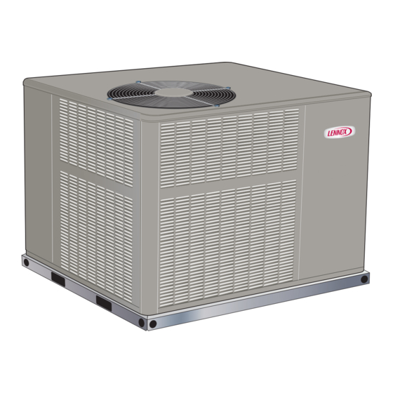
The LRP14/16 series packaged units are available in siz-
es ranging from 2 through 5 tons (7.0 through 17.6 kW).
The LRP14/16 unit is designed for HFC-410A refrigerant
and for outdoor residential use only. Units can be installed
at ground level or on rooftops. The LRP14 units utilize a
scroll compressor. LRP16GE/GX/HP units utilize a two-
stage compressor. Information contained in this manual is
intended for use by qualified service technicians only. All
specifications are subject to change. Procedures outlined
in this manual are presented as a recommendation only
and do not supersede or replace local or state codes.
Page 1
LRP14HP/AC/GE/GN
LRP16GE/HP
Advertisement
Table of Contents

Related Manuals for Lennox LRP14HP Series


Summary of Contents for Lennox LRP14HP Series
-
Page 1: Table Of Contents
UNIT INFORMATION LRP14HP/AC/GE/GN Corp. 100032 LRP16GE/HP October 7, 2021 Service Literature LRP14HP/LRP14AC/LRP14GE/LRP14GN/LRP16GE/LRP16HP SERIES UNITS Table of Contents Specifications – LRP14HP ..........2 Specifications – LRP14AC ..........3 Specifications – LRP14GE / LRP14GX ......4 Specifications – LRP14GN ..........5 Specifications – LRP16GE / LRP16GX ......6 Specifications –... -
Page 2: Specifications - Lrp14Hp
Specifications – LRP14HP General Data Model No. LRP14HP24 LRP14HP30 LRP14HP36 LRP14HP42 LRP14HP48 LRP14HP60 Nominal Tonnage Cooling / Cooling Total capacity - Btuh 22,600 28,600 34,000 40,000 46,000 57,000 Heating Total unit watts 2055 2600 3090 3635 4180 5180 Performance SEER (Btuh/Watt) 14.00 14.00 14.00... -
Page 3: Specifications - Lrp14Ac
Specifications – LRP14AC General Data Model No. LRP14AC24 LRP14AC30 LRP14AC36 LRP14AC42 LRP14AC48 LRP14AC60 Nominal Tonnage Cooling Total cooling capacity - Btuh 22,600 28,400 34,000 40,000 45,500 57,000 Performance Total unit watts 2055 2580 3090 3635 4180 5180 SEER (Btuh/Watt) 14.00 14.00 14.00 14.00... -
Page 4: Specifications - Lrp14Ge / Lrp14Gx
Specifications – LRP14GE / LRP14GX General Data Model No. LRP14GE24 LRP14GE30 LRP14GE36 LRP14GE42 LRP14GE48 LRP14GE60 Model No. - Low NOX LRP14GX24 LRP14GX30 LRP14GX36 LRP14GX42 LRP14GX48 LRP14GX60 Nominal Tonnage Gas Heat Available - See Page Page 9 -054(GX), -054(GX), 054, -072(GX), -108(GX), -108(GX), -072... -
Page 5: Specifications - Lrp14Gn
Specifications – LRP14GN General Data Model No. LRP14GN24 LRP14GN30 LRP14GN36 LRP14GN42 LRP14GN48 LRP14GN60 Nominal Tonnage Gas Heat Available - See Page Page 9 -054 -054 -054 -072 -072 -072 Cooling Total cooling capacity - Btuh 22,600 28,400 34,000 40,000 45,500 57,000 Performance Total Unit Watts... -
Page 6: Specifications - Lrp16Ge / Lrp16Gx
Specifications – LRP16GE / LRP16GX General Data Model No. LRP16GE24 LRP16GE36 LRP16GE48 LRP16GE60 Model No. - Low NOX LRP16GX24 LRP16GX36 LRP16GX48 LRP16GX60 Nominal Tonnage Gas Heat Available - See Page 9 -72, -90 -108 -126 Cooling Total cooling capacity - Btuh 23,800 35,400 47,500... -
Page 7: Specifications - Lrp16Hp
Specifications – LRP16HP General Data Model No. LRP16HP24 LRP16HP36 LRP16HP48 LRP16HP60 Nominal Tonnage Cooling / Cooling Total capacity - Btuh 23,000 35,000 47,000 57,000 Heating Total unit watts 1910 2910 3910 4950 Performance SEER (Btuh/Watt) 16.0 16.0 16.0 15.5 EER (Btuh/Watt) 12.0 12.0 12.0... -
Page 8: Electric Heat Capacities - Lrp14Hp And Ac Models - Lrp16Hp
Electric Heat Capacities – LRP14HP and AC Models – LRP16HP 5 kW 7.5 kW 10 kW 15 kW 20 kW Input No of Btuh No of Btuh No of Btuh No of Btuh No of Btuh Voltage Steps input Output Steps input Output... -
Page 9: Electrical
Electrical ELECTRIC HEAT DATA — LRP14HP Only Model No. LRP14HP24 LRP14HP30 LRP14HP36 208/230V 208/230V 208/230V Compressor Rated Load Amps 10.9 13.5 15.4 Locked Rotor Amps 59.3 72.5 83.9 Outdoor Fan Full Load Amps Motor Locked Rotor Amps Indoor Full Load Amps Blower Motor Locked Rotor Amps Maximum... - Page 10 ELECTRIC HEAT DATA — LRP14HP Only (Contd.) Model No. LRP14HP42 LRP14HP48 LRP14HP60 208/230V 208/230V 208/230V Compressor Rated Load Amps 15.9 24.3 Locked Rotor Amps 144.2 Outdoor Fan Full Load Amps Motor Locked Rotor Amps Indoor Full Load Amps Blower Motor Locked Rotor Amps - - - Maximum...
- Page 11 ELECTRIC HEAT DATA — LRP14AC Only Model No. LRP14AC24 LRP14AC30 LRP14AC36 208/230V 208/230V 208/230V Compressor Rated Load Amps 10.9 13.5 15.4 Locked Rotor Amps 59.3 72.5 83.9 Outdoor Fan Full Load Amps Motor Locked Rotor Amps Indoor Rated Load Amps Blower Motor Locked Rotor Amps Maximum...
- Page 12 ELECTRIC HEAT DATA — LRP14AC Only (Contd.) Model No. LRP14AC42 LRP14AC48 LRP14AC60 208/230V 208/230V 208/230V Compressor Rated Load Amps 15.9 24.3 Locked Rotor Amps 144.2 Outdoor Fan Full Load Amps Motor Locked Rotor Amps Indoor Rated Load Amps Blower Motor Locked Rotor Amps - - - Maximum...
- Page 13 EL E CT RI C AL D ATA – LRP14GN Model No. LRP14GN24 LRP14GN30 LRP14GN36 LRP14GN42 LRP14GN48 LRP14GN60 Line voltage data - 60Hz 1 phase 208/230V 208/230V 208/230V 208/230V 208/230V 208/230V Maximum Overcurrent Protection (MOCP) amps Minimum Circuit Ampacity (MCA) 14.4 18.2 22.7...
- Page 14 ELECTRIC HEAT DATA — LRP16HP Only Model No. LRP16HP24 LRP16HP36 LRP16HP48 LRP16HP60 208/230V 208/230V 208/230V 208/230V Compressor Rated Load Amps 11.7 16.1 21.2 27.1 Locked Rotor Amps 58.3 83.0 104.0 152.9 Outdoor Fan Motor Full Load Amps Indoor Full Load Amps Blower Motor Maximum Voltage...
- Page 15 7000 3.21 1.83 1891 9.18 5.25 7500 3.19 1.82 1853 9.12 5.21 * Consult local utility for actual heating value. Furnace input = Input Factor X Nameplate Input Above 7500 feet, call Lennox Technical Services for additional assistance. Page 15...
-
Page 16: Typical Parts Arrangement
Typical Parts Arrangement COMPRESSOR COMPARTMENT BLOWER COMPARTMENT CONDENSER FAN ASSEMBLY CONDENSATE PAN and DRAIN HEAT EXCHANGER ACCESS DOOR CONTROL BOX VENT HOOD (GE/GN ONLY) CONDENSER COIL COMBUSTION AIR OPENING (GE/GN UNITS) HEATING COMPARTMENT FIGURE 1. Typical Parts Arrangement – LRP14GE / LRP14GN TRANSFORMER CONTACTOR DEFROST CONTROL... - Page 17 Parts Arrangement – Contd. FLAME SENSOR LOW PRESSURE SWITCH FILTER / DRIER FLAME ROLLOUT LOW PRESSURE SWITCH GAUGE PORT GAS VALVE HIGH PRESSURE SWITCH HIGH PRESSURE GAUGE PORT ORIFICE BURNERS COMPRESSOR GAS MANIFOLD IGNITER FIGURE 3. Compressor Compartment – FIGURE 5. Burner Box Components – AC, GE and GN Units GE Units EVAPORATOR...
-
Page 18: Unit Applications
Refer to Product Specifications (EHB) for auxiliary heat Unit Applications selections. LRP14HP LRP16GE LRP14HP, 2 through 5 ton (7.0 through 17.6kW) model LRP16GE, 2 through 5 ton (7.0 through 17.6kW) model units, are single phase packaged heat pump units de- units, are single phase packaged air conditioning units signed for outdoor installation on a slab or rooftop in res- designed for outdoor installation on a slab or rooftop in... - Page 19 The LRP14GE/LRP14GN and LRP16GE units include an Approximately 30 seconds after the flame has been es- ignition control which controls the combustion air inducer, tablished, the circulating air blower starts. The ignition gas valve and spark electrode. It receives signals from the control inputs are continuously monitored to ensure that limit switch, the rollout switch, the pressure prove switch the limit switch, rollout switch and pressure switch are all...
- Page 20 IGNITION CONTROL (A3) FIGURE 8. Ignition Control – Gas-Heat Units Only TABLE 2. LED Diagnostic Codes – Ignition Control WARNING Slow Flash - 1 per second Normal operation, no call for Electric Shock Hazard. Can cause injury or heat death. Unit must be properly grounded in Fast Flash - 2 per second Normal operation, call for accordance with national and local codes.
- Page 21 BLOWER CONTROL BOARD (A54) – LRP16 UNITS ADJUST SELECTOR PINS (Setting affects both heat− ing and cooling modes) HEATING SPEED DIAGNOSTIC SELECTOR PINS COOLING SPEED SELECTOR PINS FIGURE 9. Blower Control Board (A54) – ECM Motor – LRP16GE / LRP16HP Blower Control –...
- Page 22 At times the light may appear to flicker or glow. This takes COOL place when the control is communicating with the motor The COOL jumper is used to determine the CFM during between cycles. This is normal operation. cooling operation. This jumper selection is activated for Read through the jumper settings section before adjusting cooling when Y1 is energized.
-
Page 23: Blower Data - Lrp14Hp
Blower Data – LRP14HP Air Volume (cfm) at Various External Static Pressures - in. w.g. Model Blower Tap Tap 1 (Fan Only) - - - - - - Tap 2 (Low Cooling) LRP14HP24 Tap 3 (High Cooling) 1000 ¹ Tap 4 (Low Electric Heat) - - - - - - - - -... -
Page 24: Blower Data - Lrp14Ac
Blower Data – LRP14AC Air Volume (cfm) at Various External Static Pressures - in. w.g. Model Blower Tap Tap 1 (Fan Only) - - - - - - - - - Tap 2 (Low Cooling) LRP14AC24 Tap 3 (High Cooling) ¹... -
Page 25: Blower Data - Lrp14Ge / Lrp14Gx
Blower Data – LRP14GE / LRP14GX Air Volume (cfm) at Various External Static Pressures - in. w.g. Model Blower Tap Tap 1 (Fan Only) - - - - - - - - - - - - - - - LRP14GE24 Tap 2 (Low Cooling) LRP14GX24 Tap 3 (High Cooling) -
Page 26: Blower Data - Lrp14Gn
Blower Data – LRP14GN Air Volume (cfm) at Various External Static Pressures - in. w.g. Model Blower Tap Tap 1 (Fan Only) Tap 2 Cooling (Low Static) Tap 3 Cooling (High Static) LRP14GN24 Tap 4 Heating (Low Static) Rise ( °F) 1005 Tap 5 Heating (High Static) Rise ( °F) -
Page 27: Blower Data - Lrp16Ge / Lrp16Gx
Blower Data – LRP16GE / LRP16GX LRP16GE24, LRP16GX24 Blower Performance 0 through 0.80 in. w.g. External Static Pressure Range Blower Control Jumper Speed Positions “ADJUST” Jumper “COOL” Speed - cfm “HEAT” Speed - cfm “CONTINUOUS FAN” Speed - cfm Setting 1100 1100 1000... -
Page 28: Blower Data - Lrp16Hp
Blower Data – LRP16HP LRP16HP24 Blower Performance 0 through 0.80 in. w.g. External Static Pressure Range Blower Control Jumper Speed Positions “ADJUST” Jumper “COOL” Speed - cfm “HEAT” Speed - cfm “CONTINUOUS FAN” Speed - cfm Setting 1100 1150 1035 NORM 1000 1000... - Page 29 DEFROST CONTROL CMC1 Defrost Control NOTE - For geographic areas that experience low tem- Defrost Interval perature and high humidity conditions (below 32°F and Timing Pins above 80% RH), the defrost timer pin must be field set at installation to a 60 or 30 minute defrost interval in order to ensure reliable system operation while in heating mode.
- Page 30 TABLE 3 Condenser Fan B4 / Fan Motor B3 – LRP14 Units Defrost Control Diagnostic LEDs LRP14 series units are equipped with a constant torque blower motor. The constant torque motor is capable of Green LED Red LED Mode maintaining a specified CFM throughout the external (DS2) (DS1) static range.
- Page 31 High Pressure Switch S4 Terminal Strip TB2 PHK-05, -07, -10 S4 is a N.C. auto-reset high pressure switch located on All heating elements require either a second-line voltage the discharge line. The switch shuts off the compressor power source or the use of the single-point power connection when discharge pressure rises above the factory setting.
- Page 32 TABLE 7 Control System Diagnostics Heat Pump Cooling System Performance Values - LED Status Flashing Rate Fault Description LRP14HP / LRP16HP One flash per Normal operation: Slow Flash Suction Superheat Liquid Subcooling second No call for heat Model + / - 3° + / - 2°...
- Page 33 5 - Test capacitor. Replace as necessary. should be checked with all gas appliances in the building at full fire. At no time should the supply gas 6 - Inspect contactor contacts for pitting or burn marks. pressure exceed 10.5 inches w.c., nor drop below Replace as necessary.
- Page 34 3 - After allowing the unit to stabilize for five minutes, BTU/HR = Cubic Feet Per Revolution X 3600 X Heating Value record the manifold pressure. 4 - Disconnect heating demand as soon as an accurate reading has been obtained. INPUT No.
-
Page 35: Wiring Diagrams And Sequence Of Operation
Wiring Diagrams and Sequence of Operation LRP14HP Unit Wiring Diagram – Constant Torque Blower FIGURE 15 Page 35... - Page 36 LRP14AC Unit Wiring Diagram – Constant Torque Blower FIGURE 16 Page 36...
- Page 37 LRP14GE Unit Wiring Diagram – Constant Torque Blower FIGURE 17 Page 37...
- Page 38 LRP16GE Wiring Diagram FIGURE 18 Page 38...
- Page 39 LRP16GE Unit Wiring – Single Phase FIGURE 19 Page 39...
- Page 40 LRP16HP Wiring Diagram FIGURE 20 Page 40...
- Page 41 LRP16HP Unit Wiring – Single Phase FIGURE 21 Page 41...
- Page 42 A-PHK Electric Heat FIGURE 22 Page 42...
- Page 43 B-PHK Electric Heat – Older Models FIGURE 23 Page 43...
- Page 44 SEQUENCE OF OPERATION – SINGLE-STAGE COM- NOTE - On early defrost controls, the defrost timing jump- PRESSOR er must be in the 90-minute defrost interval before testing the defrost mode or the control will not enter defrost test NOTE - The combustion air inducer is energized for 30 mode.
- Page 45 First and second stage cooling operate independent of Second Stage Cooling (High Capacity) each other and can modulate back and forth according to Compressor is operating in first stage cooling. Second the thermostat demand. stage thermostat demand sends voltage to rectifier plug First Stage Cooling (Low Capacity) D4.
-
Page 46: Lrp14Gn - Heating Components And Operation
LRP14GN – Heating Components and Operation Gas Valve The gas valve is factory set and does not require adjust- ment. See the table below for pressures. The gas valve should completely and immediately cycle off in the event of gas or power failure. The manual shut-off knob or switch can be used to immediately shut off gas supply. - Page 47 Operating Signal Pressure and Manifold Pressure Measurement High Signal Pressure Manifold Pressure FIGURE 26 Manifold Pressure A unit’s Manifold Pressure is the product of the Signal Pressure x the Gas Valve’s Amplification Factor (MP = ∆P x AF). If the manifold pressure is not within specification, it will be helpful to determine if it is the Signal Pressure or the Amplification Factor that is the culprit.
- Page 48 3 - Select indoor blower speed tap, which provides a d. Slide the gas valve switch to the “ON” position and initi- ate a call for heat. During steady state operation, mani- temperature rise within the range specified on the fold pressure should be: rating plate.
- Page 49 FIGURE 29. Wiring Diagram – Single Phase CT Page 49...