Advertisement
Quick Links
Installation Manual
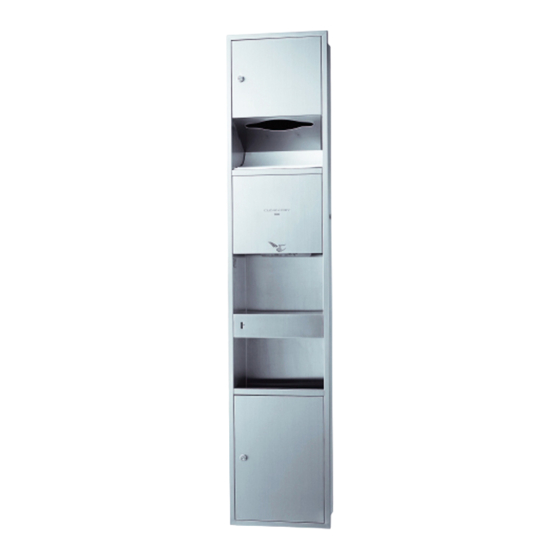
F06737S
Sensor Activated High-speed Hand Dryer (Recessed, multi-functional )
TYC602P / TYC603P
To maximize the product's performance, please follow the instructions given in this manual for correct installation. After installation, please explain in detail the
operating instructions to the customer. The product contains the user manual (warranty attached).
Safety Precautions
(For your safety, please follow these instructions)
Before installing, please read "Safety Precautions" and install properly according to their instructions.
This manual contains various symbols to enable you to install
For the following symbols, the instruction must
and use this product safely and correctly, and to prevent
be followed.
causing harm to you or other people's safety and property
damage.
These symbols and their meanings are described below.
Forbidden
Symbols
Meaning
Do not disassemble
Inappropriate operation due to ignoring
Do not install in a
these symbols may result in serious
Warning
humid location
injuries or death.
Inappropriate operation due to ignoring
Must be followed
these symbols may result in personal
Connecting the
Caution
injuries or property damages.
Ground Wire
Warning
Do not use in locations with corrosive, flammable gases.
Otherwise, product malfunctions or incorrect operations
may occur.
Forbidden
Do not modify and disassemble the product. This may
cause fires, electric shocks, injuries and product failures.
Do not
disassemble
Do not install in locations with high humidity such as
bathrooms. This may cause accidents such as current
Do not install
leakages, electric shocks or fires.
in a humid
environment
Components
Recessed Hand Dryer Main Unit
Paper towel
Main unit
dispenser
Machine
unit
Drip tray
Power cable inlet
Left, right, back
Trash bin
(3 in total)
Filter
Accessories
Installation Screws
User Manual
(Warranty attached)
6 (Φ4.5 × 30)
Warning
Electrical works must be performed by a qualified electrician
in accordance with national regulations. Incorrect installation
may cause electric shocks.
Please install a circuit breaker. Otherwise malfunctions and
current leakages may result in electric shock incidents.
Please use the specified cables. Otherwise improper
connection may cause fires.
Must be
followed
Please contract a qualified professional to install this product.
People with physical disabilities, mental disabilities and those
who lack common sense (including children) need to be
supervised by a responsible person while using this product.
Connect the ground wire to the grounding screw on the main
Connecting
unit. Failure to do so may result in electrical shocks.
the Ground
Wire
Caution
Be make sure to secure the main unit with the main body
mounting screws.
To prevent the main unit from falling forward and causing
Must be
followed
damages to the machine or injuries to personnel.
1
Main Unit
<Bottom view>
Ground Terminal
Sensor
Air nozzles
Wall surface
Heater ON/OFF
switch
Filter case
Power switch
<When the surface cover is
removed>
Keys
Ground Screw
1 (M4 × 8)
2
How to Install
2016.9
Safety precautions before installation
Electrical works must be in accordance with the relevant
regulations of the country and installations to be performed
according to the instructions given in this Installation Manual. The
installer must be qualified. If the connection is done incorrectly, the
connection terminal may ignite which may cause fires.
Warning
Please install a circuit breaker. Otherwise malfunctions and current
leakages may result in electric shock incidents.
Connect the ground wire to the grounding screw on the main unit.
Otherwise this may cause electric shocks.
Please use a dedicated circuit breaker rated for 10A current and AC220V
voltage. When fixing the wiring, you must connect an all-pole disconnection
switch protection device.
How to install the cables
Building in and wiring the junction box.
. Embed the junction box in the wall, connect the electrical cables.
※ Please use electrical cables with specifications of 1.5mm² ~ 2.5mm².
. The junction box is to be positioned on the right side of the main unit.
The center of junction box is positioned as follows
※ Back side: 1096mm vertically below the installation position, 95mm away from
the centerline.
. Cable length: extending approximately 400mm out of the wall.
Instructions for installing the main unit
. Wall installation approximate dimensions (mm): H1652 × W322 × D180
. When installing the screw into the wall, first use the expansion tube.
(Expansion tube self-configured on-site)
. During installation, the bottom side of the main unit should be
approximately 109mm from the floor surface.
322mm (+8, -0)
Junction Box
(Self-configured on-site)
109mm
Wall plugs (6)
Floor surface
Self-prepared on-site
Wall
350mm
95mm
Power cable installation hole
BACK SIDE
83mm
Wall plug installation hole
6 (3 Left, 3 Right)
83mm
Power cable
installation hole
(For ground line)
2 (1 Left, 1 Right)
83mm
90mm
Wall
Floor surface
Preparing for wall installation
. After removing the machine unit panel, remove the plastic cover, remove the
screws on the machine unit (2), and then remove the machine unit.
. After removing the drip tray, tear the transparent plastic film off the door panel,
open the door panel, take out the trash bin (invert the trash bin when removing
it).
Machine unit
panel
Plastic cover
Fixing screws (2)
(Φ4 × 10)
Drip tray
Fixing screws (2)
(M4 × 12)
Trash bin
3
Pull in the cable
. Insert wall plugs into the wall.
. Secure the bottom part of the main unit, then pull the power cable in the wall through the wiring hole
at the back side of the main unit. Pull the ground wire through a hole on the right side (or left side) of
the main unit. (As shown below)
. After the power cable is in place, and the whole unit is embedded in the wall, then use screws (Φ4.5
× 30) to secure (6).
. Finally, install the machine unit to the main unit and secure with 2 screws (M4 × 12).
174mm
312mm
11mm
Power
cable
※ Note: Due to the heavy weight of the product, please pay attention to safety during
installation, to avoid product from toppling over.
Fix the power cable
Connect the ground wire to the grounding screw on the main
unit.Otherwise this may cause electric shocks.
Warning
. Connect the power cable for stainless steel main unit to the hand dryer power
supply terminal block.
15mm
174mm
Power terminal block
Using bent power cable
Not fully inserted
134mm
Clip
Installation screws
(Φ4 × 16,1 pieces)
Power terminal block
109mm
Floor surface
4
Main unit
Machine unit
Junction
box
Screws (6)
(Φ4.5 × 30)
(See overall
installation
instructions)
Fixing
Ground
screws (2)
wire
(M4 × 12)
Connecting the
Ground Wire
15mm
Fully insert the power cable
Strip wire15mm
Power cables of varying lengths
Metal cover
Installing the Ground Wire ※
M4 grounding screw
Continued on reverse side
Advertisement

Related Manuals for Toto TYC602P


Summary of Contents for Toto TYC602P
- Page 1 . After removing the drip tray, tear the transparent plastic film off the door panel, according to the instructions given in this Installation Manual. The TYC602P / TYC603P open the door panel, take out the trash bin (invert the trash bin when removing installer must be qualified.
- Page 2 Trial operation Installation Procedure After securing the power cable, place the plastic cover over the machine unit, secure with fixing screws (2), then secure the machine After installation, perform a trial run in the following manner unit panel with screws (2). Place the trash bin in the main unit, and lock the door.