Table of Contents
Advertisement
Quick Links
SPLIT-TYPE, HEAT PUMP
AIR CONDITIONERS
SERVICE MANUAL
[Model names]
PEA-RP200GAQ
PEA-RP250GAQ
PEA-RP400GAQ
PEA-RP500GAQ
Remote controller (option)
• This manual describes only
service data of the indoor
units.
CONTENTS
2. SAFETY PRECAUTION ···································3
3. PART NAMES AND FUNCTIONS····················8
4. SPECIFICATIONS ··········································10
5. DATA ·······························································11
6. OUTLINES AND DIMENSIONS ·····················13
7. WIRING DIAGRAM ·········································16
8. REFRIGERANT SYSTEM DIAGRAM ············18
9. TROUBLESHOOTING ····································19
10. SERVICE DATA (PARTS NAME) ···················30
2010
Advertisement
Table of Contents

Related Manuals for Mitsubishi Electric PEA-RP200GAQ


Summary of Contents for Mitsubishi Electric PEA-RP200GAQ
-
Page 1: Table Of Contents
SPLIT-TYPE, HEAT PUMP 2010 AIR CONDITIONERS SERVICE MANUAL • This manual describes only service data of the indoor units. [Model names] PEA-RP200GAQ PEA-RP250GAQ PEA-RP400GAQ PEA-RP500GAQ CONTENTS 1. TYPES OF CONNECTED OUTDOOR UNITS ····2 2. SAFETY PRECAUTION ···································3 3. PART NAMES AND FUNCTIONS····················8 4. -
Page 2: Indoor Unit
PEA - RP250GAQ PUHZ-P250YHA / PUHZ-RP250YHA2 PUHZ-P200YHA x 2 / PUHZ-RP200YHA2 x 2 PEA - RP400GAQ PEA - RP500GAQ PUHZ-P250YHA x 2 / PUHZ-RP250YHA2 x 2 Indoor Unit List Specification Standard Model Model name PEA-RP200GAQ PEA-RP200GAQ.TH-AF PEA-RP250GAQ PEA-RP250GAQ.TH-AF PEA-RP400GAQ PEA-RP400GAQ.TH-AF PEA-RP500GAQ PEA-RP500GAQ.TH-AF... -
Page 3: Safety Precaution
SAFETY PRECAUTION CAUTIONS RELATED TO NEW REFRIGERANT Cautions for units utilising refrigerant R410A se new refrigerant pipes. Do not use refrigerant other than R410A. n case of using the existing pipes for R22, be careful with f other refrigerant (R22 etc.) is used, chlorine in refrige- the followings. - Page 4 [2] Storage of Piping Material (1) Storage location Store the pipes to be used indoors. (Warehouse at site or owner’s warehouse) Storing them outdoors may cause dirt, waste, or water to infiltrate. (2) Pipe sealing before storage Both ends of the pipes should be sealed until immediately before brazing. Wrap elbows and T’s in plastic bags for storage.
- Page 5 Brazing o changes from the conventional method, but special care is required so that foreign matter (ie. oxide scale, water, dirt, etc.) does not enter the refrigerant circuit. Example: Inner state of brazed section When non-oxide brazing was not used When non-oxide brazing was used Items to be strictly observed: 1.
- Page 6 Airtightness Test o changes from the conventional method. ote that a refrigerant leakage detector for R22 cannot detect R407C leakage. Halide torch R22 leakage detector Items to be strictly observed: 1. Pressurize the equipment with nitrogen up to the design pressure and then judge the equipmentÕs airtightness, taking temperature variations into account.
- Page 7 [6] Additional refrigerant charge When charging directly from cylinder · Check that cylinder for R410A on the market is syphon type. · Charging should be performed with the cylinder of syphon stood vertically. (Refrigerant is charged from liquid phase.) Unit Gravimeter [7] Service tools Use the below service tools as exclusive tools for R410A refrigerant.
-
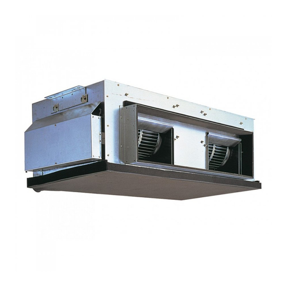
Page 8: Part Names And Functions
PART NAMES AND FUNCTIONS ● Indoor Unit Air intake duct flange Air intake (sucks the air inside the room into the unit) Air outlet Air outlet duct flange ● Remote controller (option) Once the controls are set, the same operation mode can be repeated by simply pressing the ON/OFF button. ●... - Page 9 ● Display “Sensor” indication Displayed when the remote controller sensor is used. Day-of-Week For purposes of this explanation, Shows the current day of the week. all parts of the display are shown as lit. During actual operation, only Time/Timer Display the relevant items will be lit.
-
Page 10: Specifications
SPECIFICATIONS Model name PEA-RP200GAQ PEA-RP250GAQ Mode Cooling Heating Cooling Heating Power supply (phase, cycle,voltage) 3PH 4W 50Hz 380-415V 3PH 4W 50Hz 380-415V Input 1.00 1.00 1.18 1.18 Running current External finish Galvanized steel Galvanized steel Heat exchanger Cross fin coil... -
Page 11: Data
DATA 5-1. Sound Data Indoor units PEA-RP200,250: Upper High/Lower Low OCTAVE BAND FREQ.Hz Model dB(A) 63Hz 125Hz 250Hz 500Hz 1000Hz 2000Hz 4000Hz 8000Hz PEA-RP200GAQ PEA-RP250GAQ PEA-RP400GAQ PEA-RP500GAQ Position measurement Indoor unit Inlet Outlet Measurement point... - Page 12 5-2. Fan Performance Curve Indoor units PEA-RP200GAQ PEA-RP250GAQ Fan Performance Curve 50Hz Fan Performance Curve 50Hz (Pa) (Pa) 60.0 65.0 70.0 75.0 80.0 85.0 90.0 (CMM) 45.0 50.0 55.0 60.0 65.0 70.0 (CMM) Air flow Air flow PEA-RP400GAQ PEA-RP500GAQ Fan Performance Curve 50Hz...
-
Page 13: Outlines And Dimensions
OUTLINES AND DIMENSIONS PEA-RP200GAQ Unit : mm... - Page 14 PEA-RP250GAQ Unit : mm...
- Page 15 PEA-RP400,500GAQ Unit : mm...
-
Page 16: Wiring Diagram
WIRING DIAGRAM PEA-RP200,250GAQ... - Page 17 PEA-RP400,500GAQ...
-
Page 18: Refrigerant System Diagram
REFRIGERANT SYSTEM DIAGRAM Unit : mm PEA-RP200GAQ PEA-RP250GAQ PEA-RP400GAQ PEA-RP500GAQ Strainer Heat exchanger Refrigerant GAS pipe connection Brazing Condenser/evaporator temperature thermistor (TH5) Refrigerant flow in cooling Refrigerant flow in heating Refrigerant LIQUID pipe connection Brazing ipe temperature thermistor/liquid Room temperature... -
Page 19: Troubleshooting
TROUBLESHOOTING 9-1. TROUBLESHOOTING <Error code display by self-diagnosis and actions to be taken for service (summary)> Present and past error codes are logged and displayed on the wired remote controller or controller board of outdoor unit. Actions to be taken for service and the inferior phenomenon reoccurrence at field are summarized in the table below. Check the contents below before investigating details. - Page 20 Note: Refer to the manual of outdoor unit for the details of display 9-2. SELF-DIAGNOSIS ACTION TABLE such as F, U, and other E. Error Code Meaning of error code and detection method Countermeasure Cause Abnormality of room temperature 1 Defective thermistor 1~3 Check resistance value of thermistor.
- Page 21 Error Code Meaning of error code and detection method Countermeasure Cause Freezing/overheating protection is (Cooling or drying mode) (Cooling or drying mode) working 1 Clogged filter (reduced airflow) 1 Check clogs of the filter. 1 Freezing protection (Cooling mode) 2 Short cycle of air path 2 Remove shields.
- Page 22 Error Code Meaning of error code and detection method Countermeasure Cause Abnormality of pipe temperature ther- 1 Defective thermistor 1~3 Check resistance value of thermistor. mistor / Condenser-Evaporator (TH5) characteristics For characteristics, refer to (P1) above. 2 Check contact failure of connector (CN29) 1 The unit is in three-minute resume pro- 2 Contact failure of connector on the indoor controller board.
- Page 23 Error Code Meaning of error code and detection method Countermeasure Cause ∗ Check LED display on the outdoor control cir- Indoor/outdoor unit communication 1 Contact failure, short circuit or, error (Signal receiving error) cuit board. (Connect A-control service tool, mis-wiring (converse wiring) of 1 Abnormal if indoor controller board PAC-SK52ST.) indoor/outdoor unit connecting...
- Page 24 9-3. TROUBLESHOOTING BY INFERIOR PHENOMENA Note: Refer to the manual of outdoor unit for the detail of remote controller. Phenomena Cause Countermeasure (1)LED2 on indoor controller board • When LED1 on indoor controller board is also off. 1 Power supply of rated voltage is not supplied to out- 1 Check the voltage of outdoor power is off.
- Page 25 Note: Refer to the manual of outdoor unit for the detail of remote controller. Phenomena Cause Countermeasure (2)LED2 on indoor controller board • When LED1 on indoor controller board is also blinking. Check indoor/outdoor unit connecting wire Connection failure of indoor/outdoor unit connecting for connection failure.
- Page 26 9-5. HOW TO CHECK THE PARTS PEA-RP200GAQ PEA-RP250GAQ PEA-RP400GAQ PEA-RP500GAQ Parts name Check points Room temperature Disconnect the connector then measure the resistance using a tester. thermistor (TH1) (Surrounding temperature 10:~30:) Pipe temperature Normal Abnormal thermistor/liquid (TH2) (Refer to the thermistor) 4.3k"~9.6k"...
- Page 27 9-6. TEST POINT DIAGRAM 9-6-1. Power board CN2S Connect to the indoor controller board (CN2D) Between 1 1 to 3 3 12.6-13.7V DC (Pin1 1 (+)) CNSK Connect to the indoor controller board (CNDK) Between 1 1 to 3 3 220-240V AC...
- Page 28 9-6-2. Indoor controller board CN2D LED1 Connector to the indoor LED2 LED3 Power supply power board (CN2S) Power supply Transmission (I.B) (12.5~13.7V DC) (R.B) (Indoor/outdoor) CN3C – Transmission (Indoor/outdoor) CN22 (0~24V DC) Remote controller connecting wire Non polarity – (10.4~14.6V DC) CN20 Room temperature thermistor (TH1)
- Page 29 9-7. FUNCTIONS OF DIP SWITCH AND JUMPER WIRE Each function is controlled by the dip switch and the jumper wire on control p.c. board. (Marks in the table below) Jumper wire ( : Short : Open) Jumper wire Setting by the dip switch and jumper wire Functions Remarks PEA-RP200/250...
-
Page 30: Service Data (Parts Name)
SERVICE DATA (PARTS NAME) PEA-RP200/250GAQ Suspension bracket Special washer Sirocco fan Control box Fan motor Drain pipe connection (R1) Drain pan Inlet thermistor (TH1) Liquid pipe thermistor (TH2) Gas pipe Drain pan Liquid pipe Strainer Heat exchanger 2-phase Strainer pipe thermistor (TH5) - Page 31 PEA-RP400/500GAQ Suspension bracket Control box Special washer Sirocco fan Fan motor Drain pipe connection (R1) Drain pan 2-phase pipe thermistor (TH5-2) No.2 No.1 Inlet thermistor Inlet thermistor (TH1-2) (TH1-1) No.2 Strainer No.2 Gas pipe No.2 Liquid pipe 2-phase pipe thermistor (TH5-1) Strainer Drain pan...
- Page 32 PEA-RP200/250GAQ Magnetic contactor (Fan motor Hi speed) Magnetic contactor Power supply board (Fan motor Lo speed) Ferrite core Control board Terminal block for remote controller POWER BO RD Terminal block for outdoor/indoor control board wiring connection CONTROLLER BO RD Power supply terminal block Relay view...
- Page 33 PEA-RP400/500GAQ Control board Control board Ferrite core Ferrite core No.1 unit) No.2 unit) Control board FB12 FB22 No.2 unit) FB11 FB21 SNB board CONTROLLER BOARD CONTROLLER BOARD POWER BOARD NO.1) NO.2) Magnetic NO.2) contactor POWER BOARD NO.1) TB4-1 TB4-2 view A Terminal block for remote controller Control board...
- Page 36 New publication, effective Dec. 2010 HWE10070 Specifications subject to change without notice. Printed in Japan...