Table of Contents
Advertisement
Quick Links
MIXER AMPLIFIERS
TABLE OF CONTENTS
2. SAFETY PRECAUTIONS ........................... 3
3. GENERAL DESCRIPTION ......................... 5
4. FEATURES ................................................. 5
Front ............................................................ 6
Rear ............................................................. 7
Connection ........................................... 9
6.2. Input Connections ................................ 9
6.3. Plug-In Module Input Connection ....... 10
6.4. Output Connections ............................ 10
7.1. Manual Mute ....................................... 12
Thank you for purchasing TOA's Mixer Amplifier.
Please carefully follow the instructions in this manual to ensure long, trouble-free use of your equipment.
BG-2240D
8. MOH OUTPUT ASSIGNMENT ................. 13
9. 2-CHANNEL BROADCAST ...................... 14
10. OPERATION ............................................. 15
11. INSTALLATION PRECAUTIONS ............. 15
13. VOLUME SETTING .................................. 16
14. VOLUME CONTROL COVER .................. 16
15. BLOCK DIAGRAM ................................... 17
16. DIMENSIONAL DIAGRAM ....................... 18
17. SPECIFICATIONS .................................... 19
OPERATING INSTRUCTIONS
BG-2240D-AM
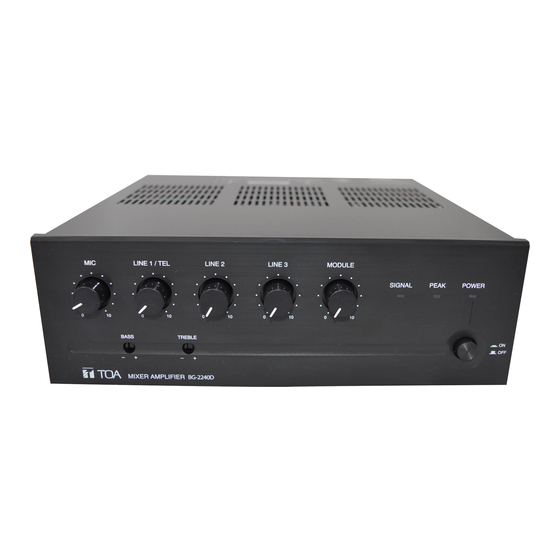
This figure represents the BG-2240D.
7.2. Automatic Mute .................................. 13
ATTACHMENT ......................................... 15
Accessories ............................................... 20
Optional Product ........................................ 20
Advertisement
Table of Contents

Related Manuals for Toa BG-2240D-AM


Summary of Contents for Toa BG-2240D-AM
-
Page 1: Table Of Contents
6.6. Remote Volume Control Connection .. 11 Optional Product ........20 7. MUTING FUNCTION 7.1. Manual Mute ........12 Thank you for purchasing TOA's Mixer Amplifier. Please carefully follow the instructions in this manual to ensure long, trouble-free use of your equipment. -
Page 2: Important Safety Instructions
1. IMPORTANT SAFETY INSTRUCTIONS • Read these instructions. • Keep these instructions. • Heed all warnings. • Follow all instructions. • Do not use this apparatus near water. • Clean only with dry cloth. • Do not block any ventilation openings. Install in accordance with the manufacturer's instructions. •... -
Page 3: Safety Precautions
• Should the following irregularity be found during use, immediately switch off the power, disconnect the power supply plug from the AC outlet and contact your nearest TOA dealer. Make no further attempt to operate the unit in this condition as this may cause fire or electric shock. - Page 4 Indicates a potentially hazardous situation which, if mishandled, could CAUTION result in moderate or minor personal injury, and/or property damage. When Installing the Unit • Never plug in nor remove the power supply plug with wet hands, as doing so may cause electric shock. •...
-
Page 5: General Description
ATTENTION L'appareil ne doit pas être exposé aux éclaboussures ou écoulements et tous objets remplis de liquide, tels que vases, ne doivent pas être sur l’appareil. 3. GENERAL DESCRIPTION The BG-2240D is 5-input mixer amplifiers for background music and general announcement.This unit is suited for use in bars, retail stores, and banquet rooms,and are equipped with the MOH output that permits 2-channel broadcast when used in conjunction with the optional booster amplifier BA-235 (35 W) or BA-260 (60 W). -
Page 6: Nomenclature And Functions
5. NOMENCLATURE AND FUNCTIONS [Front] BG-2240D This figure represents the BG-2240D. 1. Power switch Note Power is switched on and off with each This control is not active for the MOH output depression of this switch. terminal (25). 2. Power indicator 7. -
Page 7: Rear
[Rear] TOTAL IMPEDANCE 21 This figure represents the BG-2240D. 12. Line 3 input terminals • DIP switch 3 10 kΩ , –10 dB*, unbalanced, removable terminal Set to ON to place the MIC input in Mute Send block and RCA jacks. (Upper and lower RCA mode (audio signal-activated muting mode). - Page 8 17. Manual Mute terminals • DIP switch 7 Closing between (+) and (–) terminals mutes the Set to ON to output the LINE 1/TEL input to the input signal set for Mute Receive by the Function MOH output. switch B (24). •...
-
Page 9: Connections
6. CONNECTIONS 6.1. Removable Terminal Plug Connection Notes • Avoid soldering cable conductor, as contact resistance may increase when the cable is tightened and the solder is crushed, possibly resulting in an excessive rise in joint temperatures. • Use cables of AWG 12 – 24. [Cable end treatment] 2-core shielded cable Solid cable and stranded cable... -
Page 10: Plug-In Module Input Connection
Upper and lower RCA jacks are internally, passively mixed. 6.3. Plug-In Module Input Connection A single port for TOA plug-in modules is located on the unit's rear panel. Any 900 Series plug-in module can be inserted into this port. Notes •... -
Page 11: Manual Mute Terminal Connection
6.4.2. MOH output connection The MOH output is 0 dB*, 600 Ω, and balanced (transformer–isolated). * 0 dB = 1 V Note MOH OUT (ZONE2) MOH OUT (ZONE2) When connecting equpment with 600Ω 600Ω unbalanced input, short-circuit the “C” and “E” lines as shown at right. 6.4.3. -
Page 12: Muting Function
7. MUTING FUNCTION Manual mute and Automatic mute are available for the muting function. Manual mute is a function to mute the MIC, LINE 1/TEL, LINE 2, LINE 3 and/or MODULE input placed in Mute Receive mode when the manual mute terminal is short-circuited. Automatic mute is an audio-signal activated muting function to automatically mute the MIC, LINE 1/TEL, LINE 2, LINE 3 and/or MODULE input placed in Mute Receive mode when audio signals enter the MIC, LINE 1/TEL, or MODULE input placed in Mute Send mode. -
Page 13: Automatic Mute
7.2. Automatic Mute Step 1. Set the inputs to mute (Mute Send inputs) with the Function switch A. Shift the DIP switches 3 to 5 to ON position to place each corresponding input in Mute Send (muting) mode as follows. •... -
Page 14: Channel Broadcast
9. 2-CHANNEL BROADCAST Input signals set in Chapter 8 are output to the MOH output. 2-channel broadcast can be performed when the unit is used in conjunction with the optional BA-235 (35 W) or BA-260 (60 W). (Example) When MIC, LINE 1/TEL, LINE 2, LINE 3, and MODULE input signals are output to the Zone 1, and LINE 2 input signals to the Zone 2. -
Page 15: Operation
10. OPERATION After completing all connections, turn on the power switch, and check to confirm that the power indicator lights. Note When the heat sink temperature exceeds 85 °C (185 °F), the protection circuit begins to operate to disconnect the output from the circuit. The disconnected output is automatically restored as soon as the temperature returns to the normal operating range. -
Page 16: Volume Setting
13. VOLUME SETTING Output levels are adjustable with individual volume controls. For music play or announcement, adjust the corresponding volume control so that the signal indicator lights intermittently. Note that the sound quality is downgraded when the peak indicator remains lit. 14. -
Page 17: Block Diagram
15. BLOCK DIAGRAM... -
Page 18: Dimensional Diagram
16. DIMENSIONAL DIAGRAM Unit: mm (in) [Rear] [Front] 264 (10.39) [Side] 267.3 (10.52) 250 (9.84) -
Page 19: Specifications
17. SPECIFICATIONS 2240D Power Consumption Based on cULus standards 55 W – t, LPF 20kHz Input Sensitivity/ Microphone: –60 dB*, 600 Ω , electronically balanced, removable Impedance terminal block Line 1/TEL: –10 dB*/–20 dB*, 10 kΩ , electronically balanced, removable terminal block Line 2: –10 dB*, 10 kΩ... -
Page 20: Accessories
YA-920 Volume control cover ....5 Removable terminal plug (4P) ....1 Removable terminal plug (2P) ....4 Removable terminal plug (5P) ....1 Removable terminal plug (3P) ....2 • Optional Product Rack mounting bracket: MB-1000 URL: http://www.toa.jp/ 133020026800...