
Related Manuals for Extreme Networks PowerDrive Orbit

Summary of Contents for Extreme Networks PowerDrive Orbit
- Page 1 PowerDrive Orbit & X6 Quick Operations Guide Revision 1.4 6 March 2020 Extreme Equipment Rentals Page 1 of 35...
-
Page 2: Table Of Contents
PowerDrive Orbit & X6 Quick Operations Guide - rev1.4 This document should serve as a basic guide for Extreme Equipment Rental clients for planning and executing a successful PowerDrive Orbit or X6 job in North America. Contents JOB PLANNING ............................3 BHA D ............................ -
Page 3: Job Planning
PowerDrive Orbit & X6 Quick Operations Guide - rev1.4 Job Planning 1.1 BHA Design Stabilization 1.1.1 All PowerDrive BHA’s should have at least 2 stabilizers. The first stabilizer should be located on the PD control collar or directly behind it. The 2 should be 30-40 feet behind the first. -
Page 4: Hydraulics
PowerDrive Orbit & X6 Quick Operations Guide - rev1.4 1.2 Hydraulics Optimizing Hydraulics 1.2.1 The Bias Unit uses the mud flow to activate the steering pistons or pads, exerting a side force on the bit. This operational principle requires a pressure drop between the steering unit and the annulus, which can be achieved by a combination of bit nozzling and a flow restrictor inside the... -
Page 5: Flow Restrictor Use And Availability
PowerDrive Orbit & X6 Quick Operations Guide - rev1.4 Flow Restrictor Use and Availability 1.2.3 If the desired pad pressure cannot be achieved by nozzling the bit alone, a flow restrictor can be used. A PowerDrive Flow Restrictor provides additional pressure drop at the RSS tool to increase pad pressure and force without affecting the bit TFA. -
Page 6: Tool Preparation
PowerDrive Orbit & X6 Quick Operations Guide - rev1.4 Tool Preparation 2.1 Reviewing Tool Paperwork The Rotary Steerable Outgoing Systems Test (OST) paperwork is a valuable document for the Directional Driller. This paperwork will be provided by the Extreme Equipment Rental coordinator by the time tools arrive on location. - Page 7 PowerDrive Orbit & X6 Quick Operations Guide - rev1.4 PDCU-xx Tool Configuration Report 7. Tool Firmware Version – The tool firmware version is entered into the downlink timing sheet because different versions have different downlinks available. 8. Downlink Bit Period – The bit period the tool is initially configured to accept. Remember, the tool will always accept 60 second bit period regardless of whether it’s in 18 or 36 second mode.
- Page 8 PowerDrive Orbit & X6 Quick Operations Guide - rev1.4 13. Uplink Type – Use the following Compatibility Matrix to determine what MWD receiver the PowerDrive is compatible with. Uplink Type Receiver Notes ShortHop Confirm MWD is configured to receive &...
-
Page 9: Flow Loop Results
PowerDrive Orbit & X6 Quick Operations Guide - rev1.4 Flow Loop Results 2.1.2 Purpose The Flow Loop Analysis provides the critical flow rates for each specific tool and allows the DD to adjust these rates depending on mud weight as the run progresses. -
Page 10: Operating Envelope
PowerDrive Orbit & X6 Quick Operations Guide - rev1.4 Operating Envelope 2.1.3 The Flow Loop Analysis provides the critical flow rates for each specific tool and enables the DD to adjust these rates depending on mud weight as the run progresses. The operating envelop contained in the OST package is specific to that particular tool and is based on the torque measurements taken while flowing that tool in the shop. -
Page 11: Flow Restrictor Installation
PowerDrive Orbit & X6 Quick Operations Guide - rev1.4 2.2 Flow Restrictor Installation ◼ Green = Nozzle Assembly of the Flow Restrictor is ◼ Orange = Jam Nut dependent on the size of the body. ◼ Grey = Housing The 475 uses a threaded lock-nut to ◼... -
Page 12: Job Execution
PowerDrive Orbit & X6 Quick Operations Guide - rev1.4 Job Execution Tripping In / Filling Pipe There are no PowerDrive-Specific requirements on how frequently to fill pipe while tripping in. When filling pipe, it is advised to break circulation and pump at the tool’s Minimum Drill Flow for 5-10 minutes. -
Page 13: Casing Drillout
PowerDrive Orbit & X6 Quick Operations Guide - rev1.4 3.3 Casing Drillout When drilling out the shoe, keep in mind that Cement Plugs, Float Collar, Cement and Shoe Track are very different materials compared to the formation intended to drill. The bit is not designed to drill this material, especially when drilling in a soft rock environment where bits with low blade count and big cutters (aggressive design) are used. -
Page 14: Sending The Downlink
PowerDrive Orbit & X6 Quick Operations Guide - rev1.4 At any time, PowerDrive Orbit and X6 can detect the following downlinks: • Flow Downlink at 18 or 36 seconds. Verify the initial setting using the Tool Paperwork • Flow Downlink at 60 seconds •... -
Page 15: Kicking Off From Vertical
PowerDrive Orbit & X6 Quick Operations Guide - rev1.4 3.5 Kicking Off from Vertical PowerDrive tools can be used to kick off from any inclination with extensive experience in vertical kickoffs. The following points must be considered when kicking off from vertical: 1. -
Page 16: Hold Inclination And Azimuth (Hia)
PowerDrive Orbit & X6 Quick Operations Guide - rev1.4 Note: In Inclination Hold mode: • You cannot make small changes to the tool’s Steering Ratio or TF azimuth angle. • You can only steer the tool left or right by increasing or decreasing the SR in steps of 12.5%. -
Page 17: Rate Of Penetration Ranges
PowerDrive Orbit & X6 Quick Operations Guide - rev1.4 2. Stop the tool rotation 3. Cycle the pumps to take a survey. 4. If available, check for a good static survey by monitoring INCL_b and AZIM_b. If they deviate significantly from their acceptable values, then either continue in manual mode or do the survey again. -
Page 18: Powerv Lock/Unlock
PowerDrive Orbit & X6 Quick Operations Guide - rev1.4 3.7 PowerV Lock/Unlock PowerV mode is a vertical drilling mode using Gravity Tool Face (GTF) with a tool face of 180 degrees and a steering ratio of 100%. The result of this setting is that PowerDrive will continuously seek to drill vertical without further input from the directional driller at surface. -
Page 19: Sidetracking
PowerDrive Orbit & X6 Quick Operations Guide - rev1.4 1. After ensuring that the tool has been powered up and the correct quiet time has passed, as shown in the following chart, send command 2-29, PowerV Unlock/Engage to the tool. - Page 20 PowerDrive Orbit & X6 Quick Operations Guide - rev1.4 2. Allow the cement plug adequate time to harden. The cement plug must be of sufficient quality and quantity. Avoid plugging the bit nozzles by washing down with a minimal flow rate until the cement is tagged.
- Page 21 PowerDrive Orbit & X6 Quick Operations Guide - rev1.4 ream down to this mark over a 15 ft to 30 ft (5 m to 10 m) interval. The reaming ROP should be 5% to 10% of the drilled ROP in the parent wellbore, and RPM should be drilling RPM or 120 rpm to 150 rpm.
-
Page 22: Cleanup Cycles
PowerDrive Orbit & X6 Quick Operations Guide - rev1.4 • Start drilling with reduced WOB and RPM to minimize potential of localized shocks to the PowerDrive Tools (often not seen on the MWD). If high levels of shock and vibration are seen, stop drilling. -
Page 23: Re-Run Evaluation
Post Run(s) Information • Was the PowerDrive Orbit the reason for pulling out of the hole? If so then it should not be rerun. • While monitoring the real-time data was there any indication that the tool was having issues maintaining toolface? Was the tool operating as intended? •... -
Page 24: Troubleshooting
PowerDrive Orbit & X6 Quick Operations Guide - rev1.4 Troubleshooting 4.1 Low Dogleg Workflow Low doglegs can occur due to Insufficient pressure drop across the pads, insufficient pad force, high RPM, stick-slip, formation effects (Soft or unconsolidated formations or strong formation push), jamming, bit selection, BHA design or tool failure. -
Page 25: Shock & Vibration
PowerDrive Orbit & X6 Quick Operations Guide - rev1.4 4.3 Shock & Vibration Too much shock and vibration can be destructive to all BHA components and needs to be actively managed to avoid costly tool damage or, in extreme cases, parts left in hole. All well planning must include a plan to deal with high shocks and stick-slip. -
Page 26: Required End Of Run Data
PowerDrive Orbit & X6 Quick Operations Guide - rev1.4 Required End of Run Data After completion of the job the Directional Driller at the wellsite is required to send in his final deliverables to their Directional Drilling Coordinator. The Directional Drilling Coordinator is then responsible for sending the final deliverables to the XER Operations Coordinator. -
Page 27: Document Revision History
PowerDrive Orbit & X6 Quick Operations Guide - rev1.4 Document Revision History Revision Date Editor Comments 14-Nov-17 M. Oswald Initial Document Creation. Job Planning & Tool Preparation 31-Jan-18 M. Oswald Addition of Job Execution section 25-Mar-18 M. Oswald Addition of Fishing Diagrams 4-Dec-19 A. -
Page 28: Appendix 1 - Real-Time D-Points
PowerDrive Orbit & X6 Quick Operations Guide - rev1.4 Appendix 1 – Real-Time d-points: Unit Name Description INCL ° Inclination (continuous survey) AZIM ° Azimuth (continuous survey) Total G Total B (H) RTSTAT PD real time status word STEER Steering d-point TFDS °... -
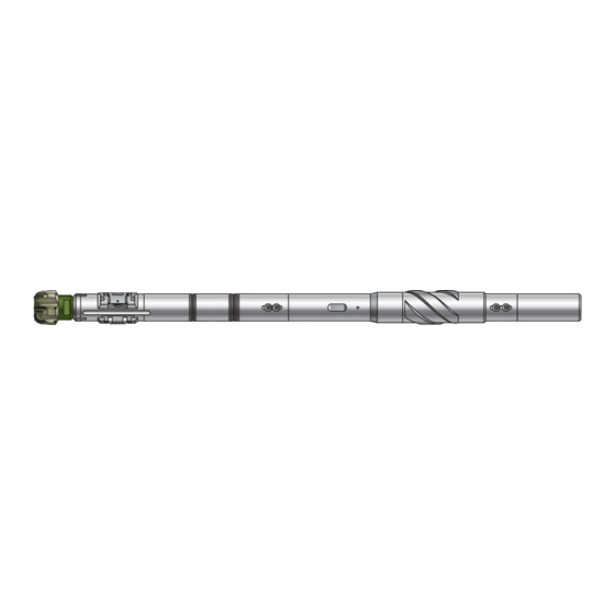
Page 29: Appendix 2 - Fishing Diagrams
PowerDrive Orbit & X6 Quick Operations Guide - rev1.4 Appendix 2 – Fishing Diagrams: 475 PowerDrive Orbit ** This Fishing Diagram is for reference only, based on iron that has not been recut. The actual component measurements for the tool configuration to be run in the hole should be taken by the DD on location. - Page 30 PowerDrive Orbit & X6 Quick Operations Guide - rev1.4 675 PowerDrive Orbit ** This Fishing Diagram is for reference only, based on iron that has not been recut. The actual component measurements for the tool configuration to be run in the hole should be taken by the DD on location.
- Page 31 PowerDrive Orbit & X6 Quick Operations Guide - rev1.4 475 PowerDrive X6 ** This Fishing Diagram is for reference only, based on iron that has not been recut. The actual component measurements for the tool configuration to be run in the hole should be taken by the DD on location.
- Page 32 PowerDrive Orbit & X6 Quick Operations Guide - rev1.4 675 PowerDrive X6 ** This Fishing Diagram is for reference only, based on iron that has not been recut. The actual component measurements for the tool configuration to be run in the hole should be taken by the DD on location.
- Page 33 PowerDrive Orbit & X6 Quick Operations Guide - rev1.4 825 PowerDrive X6 ** This Fishing Diagram is for reference only, based on iron that has not been recut. The actual component measurements for the tool configuration to be run in the hole should be taken by the DD on location.
- Page 34 PowerDrive Orbit & X6 Quick Operations Guide - rev1.4 900 PowerDrive X6 ** This Fishing Diagram is for reference only, based on iron that has not been recut. The actual component measurements for the tool configuration to be run in the hole should be taken by the DD on location.
- Page 35 PowerDrive Orbit & X6 Quick Operations Guide - rev1.4 1100 PowerDrive X6 ** This Fishing Diagram is for reference only, based on iron that has not been recut. The actual component measurements for the tool configuration to be run in the hole should be taken by the DD on location.