Table of Contents
Advertisement
Quick Links
Owner's Manual
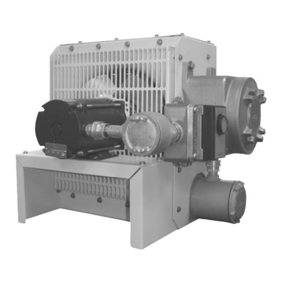
Hazardous Location Unit Heaters
DX-233 Series
This manual covers installation, maintenance and repair parts.
FM and CSA Approved for the following classified areas:
Class I, Divisions 1 & 2, Groups C & D
Class II, Divisions 1 & 2, Groups F & G
Operating Temperature Code T3C - 320°F (160°C)
or
Class I, Divisions 1 & 2, Groups C & D
Class II, Divisions 1 & 2, Groups E, F & G
Operating Temperature Code T3C - 320ºF (160ºC)
See Data Plate for Specific Area Classification
For details on the particular hazardous environments having the potential for explosion, refer to Articles 500 through 516 of the
National Electric Code, and/or Section 18 of the Canadian Electric Code, Part I.
7211390100R01
DX23-2199-83-1EF
Advertisement
Table of Contents

Related Manuals for Dimplex DX-233 Series


Summary of Contents for Dimplex DX-233 Series
- Page 1 Owner’s Manual Hazardous Location Unit Heaters DX-233 Series This manual covers installation, maintenance and repair parts. FM and CSA Approved for the following classified areas: Class I, Divisions 1 & 2, Groups C & D Class II, Divisions 1 & 2, Groups F & G Operating Temperature Code T3C - 320°F (160°C)
- Page 2 WARNINGS Installation and maintenance personnel should familiarize themselves with this manual and all the WARNINGS before installing or working on this heater to avoid potential hazardous conditions, severe property damage, personal injury or death. 1. To reduce the risk of ignition of hazardous atmospheres: 11.
-
Page 3: Installation
GENERAL 4. See figure below for minimum installation clearances: The air heaters are designed for comfort heating and should not be used in ambient temperatures exceeding 104ºF (40ºC). The units may be wall, pole or ceiling mounted. They utilize a hermetically sealed, liquid-to-air heat exchanger containing immersion type electric heating elements. -
Page 4: Operation
consistent with the temperature rating of the wire being 3. ‘Fan Only’ Switch: used. Use minimum 75°C rated wire. Refer to the electrical wiring diagram and follow these 7. Proper installation of the heater requires that an adequate steps: grounding conductor be connected to the ground terminal. a.) Do not attempt to install a “Fan Only”... -
Page 5: Maintenance
e.) Place the fan switch in the auto position. install gasket material of any type at these joints. A f.) The fan should go off. light coating of anti-seize compound is applied to the g.) Set the temperature control thermostat to a threads to prevent seizing. - Page 6 B. Replacing the Temperature High-Limit Cutouts: a. Disconnect the heater electrical power 1. Disconnect the heater electrical power supply supply. and remove the heater enclosure cover. b. Disconnect the motor supply wires from 2. Remove the wire barrier to expose the high the contactor in the wiring enclosure.
-
Page 7: Replacement Parts
REPLACEMENT PARTS 1. All replacements must be factory supplied to ensure safe heater operation. 2. Mark wires and refer to wiring diagram to ensure proper electrical connections. Reference heater catalog number and item number in figures below when contacting factory for replacement parts. Contact factory for items not shown. - Page 8 Ground Lug Disconnect Switch Track Transformer Main Contactor Transformer Fuse & Fuse Block Main Mounting Bridge Dimplex North America Limited 1367 Industrial Road Cambridge ON Canada N1R 7G8 1-888-346-7539 • www.dimplex.com © 2011 Dimplex North America Limited Page 8 of 25...
- Page 9 Supplemental Instructions for 233 Series Hazardous Location Unit Heater Heat Exchanger Removal & Replacement This document provides supplemental instructions to assist with the replacement of the heater core. Refer to owner’s manual for detailed installation, operation, and maintenance instructions, as well as cautions regarding installation and operation of explosion-proof equipment.
- Page 10 2. Rotate heater onto its side and remove cabinet bottom, heater enclosure cover, and the wiring enclosure cover. Also remove single heat exchanger mounting bolt on left side. Wiring Enclosure Heater Enclosure Heat Exchanger Mounting Bolt ...
- Page 11 3. Disconnect heater wires from the contactor and control wiring for the thermal cutout. Loosen locknut from conduit entering enclosure. Heater Wiring Grommet & locknut 4. Thread conduit into wiring enclosure to disengage heater enclosure. If unit has conduit union, loosen union and thread conduit into wiring enclosure. Conduit Union ...
- Page 12 5. Slide heat exchanger out of the bottom of the cabinet.
- Page 13 6. Locate tag on heat exchanger and verify replacement core matches original.
-
Page 14: Heat Exchanger Installation
Heat Exchanger Installation 1. To install, slide heat exchanger through the bottom of the cabinet while guiding the heater/control wires into the conduit. 2. Loosely install left side heat exchanger mounting bolt, temporarily rotate heat exchanger/cabinet and install right side heat exchanger mounting bolts. You may want to leave these three bolts loose until conduit has been fully threaded into heater enclosure.