Table of Contents
Advertisement
Quick Links
Advertisement
Table of Contents

Related Manuals for Neltronics DVR-4000HDQ

Summary of Contents for Neltronics DVR-4000HDQ
- Page 1 4CH HD DVR Operating Manual DVR-4000HDQ - 4CH HD DVR Thank you for using our Mobile DVR. Please read this User’s Manual carefully to ensure that you can use the device correctly and safely. The contents of this manual are subject to change without notice.
-
Page 2: Table Of Contents
Contents Specifications............................ 1 1 Main Features..........................3 2 Wiring Diagram..........................5 3 Connection - Front Panel......................5 3.1 SD card slot........................5 3.2 Electronic lock........................6 3.3 IR Receiver......................... 6 3.4 LED Indicators........................7 3.5 LCD monitor........................7 3.6 NO LCD monitor......................11 4 Connection - Front Panel......................11 4.1 Camera cable input...................... - Page 3 7.2 Camera name setting......................31 7.3 System Language setting....................32 7.4 Audio Out.......................... 32 7.5 OSD display setting......................33 7.6 Menu on..........................34 7.7 Speed..........................35 7.8 GPS............................36 7.9 Mirror..........................37 8 Network............................37 8.1 LAN port and server setting................... 38 8.2 WIFI network setup and server setup................39 8.3 3G/4G control and its network setup................41 8.4 Network Status.........................
-
Page 4: Specifications
Specifications 4CH HD DVR Operating system Linux Operating interface Graphical menu operation interface(OSD) System Video permission Administrator & user setting Video input Max 4 x 1080P analog high definition CVBS output 1CH 6pin aviation connector output PAL/NSTC HDMI output 1CH type-A connector output, 1080P Video Video display 1 or 4CH... - Page 5 1 channel RS232 1 channel Interface RS485 1 channel for communication NULL RJ45 1 channel USB2.0/USB3.0 USB3.0 x 1 3G/4G HSPDA/EVDO/FDD-LTE/TDD-LTE module optional Wireless WIFI optional WIFI hotspot/AP optional Internal or external GPS/GLONASS module, coordinate/speed can be encoded in video stream and upload to server by wireless communication G-Sensor Available...
-
Page 6: Main Features
1 Main Features Controlled by touch screen All settings and operations could be done through the monitor if connected with the suggested touch screen. The main function is specially needed in awkward occasions for using mouse, like in vehicles. Video and Audio 4 channels * 1080p, 4 video inputs with audio ... - Page 7 outputs Over-speed alarm and accelerated-speed alarm Motion detection alarm G-sensor alarm Video loss alarm Panic button alarm Charger 5V, 1.3A output from the USB interface to mobile devices, such as mobile phone. Security User password protection. The DVR can only be accessed with correct ...
-
Page 8: Wiring Diagram
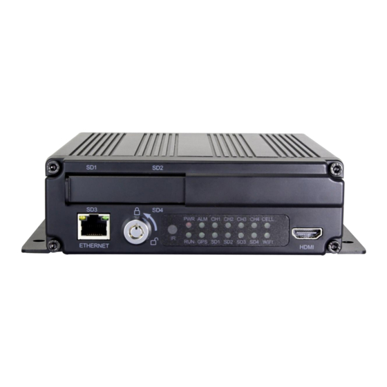
2 Wiring Diagram 3 Connection - Front Panel ① SD Card Slot ④ IR Receiver ② Ethernet(RJ45) ⑤ LED Indicators ③ Electronic lock ⑥ HDMI output 3.1 SD card slot SD card type: Each card Max. Capacity 128G Insert、remove SD card Step 1: Use the key to unlock and open front plate Step 2: Insert SD card to SD card slot Step 3: Close the front plate and use the key to lock... -
Page 9: Electronic Lock
3.2 Electronic lock Close the front cover and turn the groove by the key to the icon “off”, so as to prevent hard disk drive from moving out. Or turn to the icon “on” to open the front cover. Electronic Lock Function:DVR will stop recording and buzzer beeps when lock is ... -
Page 10: Led Indicators
3.4 LED Indicators PWR: Red LED, lights up when DVR is powered on, and goes out when power is cut off. RUN: Keeps on when DVR is being launched and flashes when DVR is running. ALM: Alarm indicator. It keeps on with the record when there is Alarm-in, G-sensor activation or motion detection or speed or panic button event alarm. - Page 11 ① HD monitor power button, LED red for standby mode, and green for working mode ② HDMI connector ③ HDMI cable ④ HD monitor 6pin aviation cable connector, with Power and Video/Audio pin.
- Page 12 The parameter list of 7/10 inches HD monitor 10 inches HD monitor 7 inches HD monitor Description HD 10.1"Color monitor HD 7"Color monitor Features used for HD DVR used for HD DVR Resolution 1024 x 600 (RGB) 1024 x 600 (RGB) Maximum Number of Cameras Audio input...
- Page 13 Monitor remote control How to connect the monitor Connect to high-definition LCD monitor (7/10 inches HD monitor) 1.By HDMI cable 2.By 6pin aviation cable Each of the method can display and touch control the DVR. Connect to standard LCD monitor (CVBS) 1.By 4pin AVOUT on the DB44 camera cable.
-
Page 14: Lcd Monitor
3.6 NO LCD monitor If the DVR is not connected to any monitors, it will remind the customer of the exception by Buzzer alarm . Buzzer warning functions are as follows: No matter what types of alarm event occur(including Alarm recording 1~8, Motion ... -
Page 15: Camera Cable Input
4.1 Camera cable input Camera connection on rear panel is 4CH aerial port. Pin-out: Camera Connection Four cameras can be directly, or via extension cable connected to the 4CH aerial ports on the DVR rear panel. 4.2 Wifi Connector Wifi antenna socket and wifi antenna, as shown in the picture. 4.3 Built-in GPS Connector Built-in GPS antenna socket and GPS antenna, as shown in the picture. -
Page 16: Cellular Connector, Tx/Rx
4.5 Cellular Connector, TX/RX Cellular antenna socket and Cellular antenna, as shown in the picture. 4.6 Power input (10-36V) Signals: 3. V+ (9~36V) 4. ACC 1. GND 2. GND Connection Method: Connect the ignition to ACC (the yellow wire of the power cable). Connect the “+” and “-” pole of battery to V+ (the red wire) and GND (the black wire) of the DVR. -
Page 17: Alarm-In & Alarm-Out
4.7 Alarm-In & Alarm-Out Alarm, speed sensor, temperature sensor connecting cable: Pin-1 Pin-3 Pin-5 Pin-7 Pin-9 Pin-11 Pin-13 Pin-15 Pin-17 Pin-19 Alarm1 Alarm2 Alarm3 Alarm4 Reverse Brake Left Right Speed Alarm Input 1~4 Reverse Brake Input Left Input Right Speed Input Input... - Page 18 3、If Alarm input 1 is active and combined with Alarm output 1, the Alarm output 1 will output a high-level voltage to trigger other device. 4、SPEED+&SPEED- These 2 cable is for speed detection and needs to connect to speed line on vehicle. Check the real-time vehicle speed with the vehicle speedometer: Wiring diagram: The vehicle speedometer is driven by the Speed sensor, see the right figure.
-
Page 19: Panic Button (Optional)
4.8 Panic button (Optional) Overview The LEDs are used to show the device’s working status. But when the device is installed in the vehicle,it is not easy to check the LED on the front panel.Each of the LED indicates the corresponding status. -
Page 20: The Menu
a. When pressed, will trigger a manual event b. When pressed, will temporarily illuminate the Event LED 5 The Menu The default setting can meet the requirement of most of users. Menu Introduction Press [MENU] on the remote or Touch the bottom area, the LOGIN page will be displayed on the LCD screen. -
Page 21: Manually Record
⑦ Cell Sign ⑧ WiFi Sign ⑨ Video Loss Sign ⑩ Menu Press [Area 10] to display MENU Sign ⑪ Channel Name Sign 5.1 Manually Record Click this icon to start or stop recording. Video files are saved in NORMAL list of Player menu. - Page 22 Normal: Normal recording list, including Normal Recording, Power on Recording, Schedule Recording Event: Alarm recording list, including alarm recording 1~8, Motion detection recording, G-force recording, Speed recording, Panic button recording Type Recording Time Control Mode View Position Normal recording Manual control Normal list Power on recording Manual control...
-
Page 23: Log
5.3 Log System memo checking, memo output 5.4 Display mode switching Mode switch button: click the button, preview interface will switch from the quad display to single display, CH1. -
Page 24: System
5.5 System System settings button: Click the button system will enter the setup menu.A prompt dialog will display "Unable to record in set-up mode! Continue?” Click OK to enter. -
Page 25: Disk
5.6 Disk Disk management button: click the disk management button, you can view the SD cards and USB status. ① Disk type ② ALL:The total capacity of disk,free:The residual capacity of disk If ALL shows 0.00MB, it means that DVR does not have access to this type of disk ③... -
Page 26: Volume
If the disk cannot be formatted, please check whether: 1. There is a disk in the slot 2. All recordings are turned off 3. The FTP button is turned off ⑤ It shows that the disk needs to be formatted before it can be used. Generally all new disks need to be formatted before they can be used 5.7 Volume Modulation:0 is the minimum volume, and 10 is the maximum volume... -
Page 27: Record Setup
6 Record Setup 6.1 Power On Rec Recording will start when power is on if set the 'Power On Rec’ ON. Default is ON. -
Page 28: Cyclic Rec
6.2 Cyclic Rec New video files will overwrite the previous ones when disk is full if setting the Continuous Rec ON. Recording will stop when disk is full if setting the Continuous Rec OFF. Overwriting will not cover event recording files. 6.3 Event Rec Event recording type includes motion detection triggered alarm, G-sensor triggered alarm, alarm 1 ~ 8 triggered... -
Page 29: Video Quality
6.4 Video Quality The major stream is used for video storage. The minor stream is used for video backup and network transmission. ① Resolution There are 4 kinds of optional resolution in Main stream menu, 1080P, 720P, D1 (PAL), D1 (NTSC), and 2 kinds of optional resolution in Sub stream menu,D1 (PAL), D1 (NTSC).The higher the resolution &... - Page 30 SSD/HDD/SD capacity Video Quality File length 8 * 1080P、4Mpbs ≈150h 8 * 720P、2Mpbs ≈300h ≈600h 8 * D1、1Mpbs ≈1200h 1 * 1080P、4Mpbs ≈2400h 1 * 720P、2Mpbs ≈4800h 1 * D1、1Mpbs ≈38h 8 * 1080P、4Mpbs ≈75h 8 * 720P、2Mpbs ≈150h 8 * D1、1Mpbs 4*128G ≈304h 1 * 1080P、4Mpbs...
-
Page 31: Record Channel
6.5 Record Channel After turn on recording (including all types) and select the recording channel, the corresponding channel will be recorded. If turning off the video channel, the corresponding channel will not be recorded even if the recording function is on. Note: The config is for normal record and NOT for event record. -
Page 32: Motion Sensitivity
6.8 Motion Sensitivity Motion detection recording and sensitivity level setting: When there is an object moving and its movement amplitude exceeds the preset motion detection sensitivity level, event recording will be triggered. For this kind of event record or alarm record, the pre-record time will be set as 15s and the post-event time is configured by Event Duration above. -
Page 33: Display
7 Display 7.1 Camera display setting Parameter setting for each corresponding camera channel: including brightness, contrast, saturation, hue. By default, all setting values are 50. Corresponding value can be changed by pressing and moving the bar to left or right. -
Page 34: Camera Name Setting
7.2 Camera name setting Camera name: Set channel name, the channel name then will be displayed at the bottom of that channel.Press the channel name on menu, there will be an keyboard menu pop up to input a new channel name. Each channel contains max. -
Page 35: System Language Setting
7.3 System Language setting 7.4 Audio Out Audio out: choose the audio output channel in split mode... -
Page 36: Osd Display Setting
7.5 OSD display setting OSD configuration, select whether to display time, channel name, license plate in video (if yes, all these information will be written in video and can be seen in playback) -
Page 37: Menu On
7.6 Menu on Set duration of menu display User permissions list User Name admin guest Password Modification yes Initial Password Enter Permissions Enter the menu of Playback menus DVR has two kinds of permissions: admin permissions and guest permissions ... -
Page 38: Speed
When the status of Menu Lock is On, username admin and password are needed to enter menus like Record,Playback, Log, System and Disk.Only the Playback menu can be entered when user name guest and its password are entered 7.7 Speed There are two speed source, one is from GPS and the other from vehicle speedometer, as described above about DB26 cable. -
Page 39: Gps
7.8 GPS When GPS is set as on, latitude, longitude and speed will be recorded into video files.The menu provides GPS information of latitude / longitude, detectable satellites, accessible satellite etc. Mode:GPS status,it will be shown as below: connected disconnected Connecting... -
Page 40: Mirror
7.9 Mirror ON: Turn on Mirror function OFF: Turn off Mirror function 8 Network... -
Page 41: Lan Port And Server Setting
8.1 LAN port and server setting DHCP: Dynamic Host Configuration Protocol, when it is on, it is dynamic IP, when it is off, it is static IP, you need to input IP address, sub-net mask and gateway manually. MAC address can be auto assigned or revised OK:Press OK to save setting and exit Cancel:Press cancel to exit menu without saving settings... -
Page 42: Wifi Network Setup And Server Setup
8.2 WIFI network setup and server setup WIFI: WIFI on/off DHCP: DHCP means Dynamic IP switch. When DHCP is on, that is dynamic IP. If DHCP is off, that is static IP. Static IP requests to manual input IP address, mask and gateway. Mac address can be automatically assigned or revised. - Page 43 Step 4:Click SSID sub-menu and the WIFI hot spot shows up. Select which hots pot to connect and enter the password. Step 5:Click OK and quit the WIFI setup interface. Step 6:Input WIFI Server IP and Port in “Network-Server Setup” page. Step 7:WIFI network status is “CONNECT SUCCESS”...
-
Page 44: 4G Control And Its Network Setup
8.3 3G/4G control and its network setup Cellular: Cellular is on, meaning that 3G/4G is on. Network Standard: WCDMA by default. APN &Access Number: Normally, user don’t need to enter user name and password for APN and Access number. The default setting is available. If it can’t communicate with the network under the default setting, please consult your local network carrier. - Page 45 step 5:Input the APN and Access Number correctly. Access Number can be skipped. step 6:Click “OK” to exit CELL setup menu. step 7: Input 3G/4G Server IP and Port in “Network-Server Setup” page. step 8: Cellular network status is “Success” and server status is “Online”...
-
Page 46: Network Status
8.4 Network Status The user can check information such as LAN IP address、MAC address、WIFI network status、WIFI IP address、WIFI signal strength、3G/4G network status、3G/4G signal strength, and Server status. Additionally, users can verify whether network connection is successful or not. LAN IP:Refers to the static IP set on Network-LAN page or the dynamic IP which is obtained automatically. - Page 47 Cellular : The on/off status of cellular acquired from Network-cellular page Wireless RSSI:3G/4G signal strength icon Module type:Display the types of 3G/4G module, the parameters and the corresponding types shown are as follows 3G:3G module 4G:4G module Wireless Status: Value and corresponding meanings 1:Module initialization 2:Module exception 3:No SIMcard...
-
Page 48: Server
8.5 Server 8.6 FTP... -
Page 49: System
9 System... -
Page 50: Log In Setup
9.1 Log in setup Set user name and password for boot up License plate number setup Set license plate number and IP number... -
Page 51: System Time Setup
9.3 System time setup 9.4 Scheduled Recording Enable:Set scheduled recording ON/OFF. Start:Set start time of scheduled recording. End:Set end time of scheduled recording. -
Page 52: Exception
Week-day:Set scheduled recording by weekdays. Select the weekdays to set preset. Scheduled Recording: * Supports up to four appointed tasks, the recording duration is counted in minutes. * Recording time can overlap. * The start time of scheduled recording must be set ahead of the end time. 9.5 Exception... -
Page 53: Acc Settings
9.6 ACC settings Current vol.: Voltage of the working DVR Shutdown vol.: Shutdown voltage function will take effect after DVR starts working for 10mins. DVR would shut down automatically if current voltage is lower than shutdown voltage, it would reboot only when the voltage is above the value. ACC Delay: DVR will continue recording for a few seconds after ACC is disconnected. - Page 54 Alarm1~Alarm4: Customized alarm recording Reverse:Reversing alarm recording, parking line cursor will display when reverse alarm is triggered. Brake:Brake alarm recording, brake sign will display when brake alarm is triggered. Left:Turning- left alarm recording, turn-left cursor will display when turn left alarm is triggered. Right:Turning- right alarm recording, turn-right cursor will display when turn right alarm is triggered.
- Page 55 Trigger Level:There are 3 options of Trigger Level , the options “Low” and ” High” are used for turning on alarm function. “Low” is generally used for debugging while “High” will be selected to turn on alarm function for on road use.
-
Page 56: Update
being triggered, B will then record. However, if B is no longer being triggered now, it will not record. If alarm B is triggered and at the process of recording. However, alarm A, whose priority is higher than B, is triggered then, B will stop recording at once, and A will start to record 9.8 Update ... - Page 57 Step 3:When “Updated success!” shows on the DVR monitor, DVR will auto reboot. Step 4:After reboot, please check if the version is the same as the one you copy to USB disk or SD card. Please go to Menu -> System -> Info to check. ...
- Page 58 “dv425_upgrade_never_rename” Step 2: Copy the package to USB disk or SD card root directory, and insert it to DVR. Step 3:Power off the DVR and reboot it, then it will auto upgrade. Or in the menu Menu -> System -> Update, click OK to confirm to upgrade. Both method can start the upgrade process.
- Page 59 Note: Use “dv425_upgrade_never_rename” package to upgrade, when “update success!” shows on the screen, we must unplug the USB disk or SD card, or else the DVR will go into infinite loop for upgrade and will not boot up. SOLUTION: Unplug the USB disk or SD card with upgrade package. DVR will stop the upgrade process and boot up successfully.
-
Page 60: Configuration
Note: remote upgrade package can’t named “dv425_upgrade_never_rename”. 9.9 Configuration Configuration Import: Import the configuration information from USB memory flash devices. Configuration Export: Export Log to USB memory flash devices. Factory Default: Click RESET to restore factory setting. -
Page 61: System Info
9.10 System Info System Info:Software version number. -
Page 62: Faq
10 FAQ 1) The system can’t start? Usually this problem results from the incorrect power connection. Please follow the steps below to check the power connection: 1. Check the input power, whether the power wire is connected correctly, whether the ground wire is connected to the battery, and whether the fuse on the power wire is in good condition. -
Page 63: Appendix
11 APPENDIX APPENDIXⅠ:Abbreviation & Description Rec. Record Hard Disk Drive G-sensor Accelerometer sensor Secure Digital Memory Card Global Positioning System Universal Serial Bus WIFI WIreless-FIdelity Alarm Camera VLOSS Video Loss Audio Video Interleaved COMM Communication On-Screen Display Error Access Point Name Memory DHCP Dynamic Host Configuration... -
Page 64: Appendixⅱ:accessories
APPENDIXⅡ:Accessories Accessories Quantity Description Accessories Quantity Description Remote Power Cable Control 4CH HD DVR Key GPS Antenna optional WIFI Antenna optional Alarm, speed sensor, temperature sensor connecting cable 6p to 4p conversion cable, supplied... -
Page 65: Appendixⅲ:compatibility Storage List
APPENDIXⅢ:Compatibility Storage List SD Card Typical Typical Test Test Brand Card Read Write Capacity Read Write Model Name Interface Remarks Name Type Speed Speed (GB) Plug Speed Speed (MB/s) (MB/s) (MB/s) (MB/s) Test Read/Write, Lexar 128G SDXC Standard Lexar Update software, 633X UHS-I...