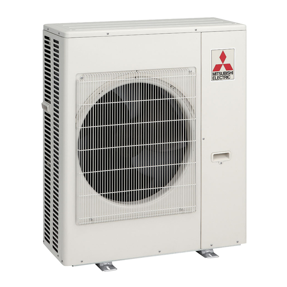
Summary of Contents for Mitsubishi Electric MXZ-6E120VAD2
- Page 1 Split-type Air-Conditioner MXZ-6E120VAD2 For INSTALLER Installation Manual English • This manual only describes the installation of outdoor unit. When installing the indoor unit, refer to the installation manual of indoor unit.
-
Page 2: Table Of Contents
/ for difference *9 for multi system A *10 multi-system 3-core 4-core MXZ-6E120VAD2 230 V 50 Hz 32 A 25 m / 80 m 15 m 25 / 80 20 g/m 4.0 mm 1.0 / 1.5 mm *1 Connect to the power switch which has a gap of 3 mm or more when open *6 Refrigerant pipe bending radius must be 100 mm or more. - Page 3 1-3. SELECTING OPTIONAL DIFFERENT-DIAMETER JOINTS If the diameter of connection pipe does not match the port size of outdoor unit, use optional different-diameter joints according to the following table. (Unit: mm (inch)) Optional different-diameter joints (port size of outdoor unit → diameter of connection pipe) Port size of outdoor unit 6.35 (1/4) →...
- Page 4 1-5. INSTALLATION DIAGRAM After the leak test, apply insulat- ing material tightly so that there ACCESSORIES is no gap. Check the following parts before installation. (1) Drain socket When the piping is to be attached to a wall containing metals (tin plated) (2) Drain cap or metal netting, use a chemically treated wooden piece 20 mm or...
-
Page 5: Outdoor Unit Installation
2. OUTDOOR UNIT INSTALLATION 2-1. INSTALLING THE UNIT • Be sure to fix the unit’s legs with bolts when installing it. • Be sure to install the unit firmly to ensure that it does not fall by an earthquake or a gust. • Refer to the figure in the right for concrete foundation. • Do not use the drain socket and the drain caps in the cold region. Drain may freeze and it makes the fan stop. • Remove the tape on the panel when opening the package. (DO NOT remove the LABELS on the panel.) Fix here with Anchor leg M10 bolts. -
Page 6: Flaring Work And Pipe Connection
3. FLARING WORK AND PIPE CONNECTION 3-1. FLARING WORK 1) Cut the copper pipe correctly with pipe cutter. (Fig. 1, 2) 2) Completely remove all burrs from the cut cross section of pipe. (Fig. 3) No good Good • Aim the copper pipe downward while removing burrs to prevent burrs Copper from dropping in the pipe. - Page 7 4-2. GAS CHARGE Stop valve Perform gas charge to unit. 1) Connect gas cylinder to the service port of stop valve. Liquid Union pipe 2) Perform air purge of the pipe (or hose) coming from refrigerant gas cylinder. 3) Replenish specified amount of the refrigerant, while operating the air conditioner Union for cooling.
-
Page 8: Pumping Down
4-5. TEST RUN • Test runs of the indoor units should be performed individually. See the installation manual coming with the indoor unit, and make sure all the units operate properly. • If the test run with all the units is performed at once, possible erroneous connections of the refrigerant pipes and the indoor/outdoor unit connecting wires cannot be detected. - Page 12 HEAD OFFICE: TOKYO BUILDING, 2-7-3, MARUNOUCHI, CHIYODA-KU, TOKYO 100-8310, JAPAN VH79B003H01...


