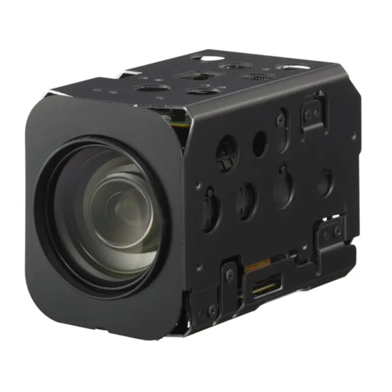
Sony FCB-EH6300 Technical Manual
Color camera module
Hide thumbs
Also See for FCB-EH6300:
- Brochure (4 pages) ,
- Brochure (4 pages) ,
- Specification sheet (4 pages)

Related Manuals for Sony FCB-EH6300


Summary of Contents for Sony FCB-EH6300
- Page 1 A-E23-100-12(1) Color Camera Module Technical Manual FCB-EH6300 2011 Sony Corporation...
-
Page 2: Table Of Contents
Table of Contents Features ................3 Precautions ............... 4 Locations of Controls ............5 Basic Functions ..............6 Overview of Functions ..............6 Eclipse ....................21 Spectral Sensitivity Characteristics .......... 21 Vibration Specifications ............... 21 Initial Settings, Custom Preset and Backup ......22 Mode Condition ................ -
Page 3: Features
Overview Features • This camera uses a 1/2.8" Exmor CMOS image sensor • A title composed of up to 11 lines can be set for (approx. 3.27 million effective pixels) that supports displaying on the screen. 20 characters can be used on FULL HD (high definition) to produce high-quality one line. images. • Adjustable AE response speed • Using progressive scan, images with a wide dynamic range can be obtained with the newly developed image signal processor (Wide Dynamic Range With consideration given environmental protection, function). Furthermore, it is possible to automatically this module is designed to operate with low power switch to this Wide Dynamic Range function, which consumption and also incorporates lead-free and enables you to obtain optimal images ranging from halogen-free circuit boards. the dark areas of a subject to the light areas. • The camera is equipped with a bright zoom lens with 20× optical zoom and F1.6 aperture (optical zoom + digital zoom = 240×). • Low-noise images can be obtained even in low-light environments using the Noise Reduction function. • Video signals can be output as digital and analog Y/Pb/Pr outputs. Depending on register settings, you can select from a variety of digital output methods: 1080p/30, 1080p/29.97, 1080p/25, 1080i/60 (Frame out: 30PsF), 1080i/59.94 (Frame out: 29.97PsF), 1080i/50 (Frame out: 25PsF), 720p/60, 720p/59.94, 720p/50, 720p/30, 720p/29.97, 720p/25. • An infrared (IR) Cut-Filter can be disengaged from the image path for increased sensitivity in low light environments. The ICR will automatically engage depending on the ambient light, allowing the camera to be effective in day/night environment. • VISCA is a communications protocol, which enables the camera to be controlled remotely from a host computer/controller. -
Page 4: Precautions
Overview Precautions In case of abnormal operation, contact your authorized Software Sony dealer or the store where you purchased the product. Use of the demonstration software developed by Sony Corporation or use of the software with customer developed application software may damage hardware, Phenomena specific to CMOS image sensors the application program or the camera. Sony Corporation is not liable for any damages under these The following phenomena that may appear in images conditions. are specific to CMOS (complementary metal-oxide semiconductor) image sensors. They do not indicate malfunctions. Operation Rolling shutter Start the camera control software on your computer As CMOS image sensors use shutters that capture after you turn on the camera and the image is images line-by-line, there is a slight time difference displayed. between the top and bottom of an image. As a result, images may appear skewed if the camera is moved. Operation and storage locations White flecks Do not shoot images that are extremely bright (e.g., Although the CMOS image sensors are produced with light sources, the sun, etc.) for long periods of time. Do... -
Page 5: Locations Of Controls
Locations of Controls Locations of Controls Front Back Bottom Lens CN501 jack CN601 jack Tripod screw hole When a tripod is used, please use 7 mm ( in.) or less screw to attach it to the camera. Also, please be sure to attach the tripod securely. -
Page 6: Basic Functions
Basic Functions Basic Functions Overview of Functions In general • Power On/Off VISCA commands are the basis of camera control. Powers the camera on and off. When the power is off, the camera is able to accept only the lowest level of Timing Chart VISCA Commands; the display and other features are turned off. As VISCA Command processing can only be carried out one time in a Vertical cycle, it takes the maximum • I/F Clear 1V cycle time for an ACK/Completion to be returned. Clears the Command buffer of the FCB camera. If the Command ACK/Completion communication Clearing the buffer can also be carried out from the time can be cut shorter than the 1V cycle time, then control application software when the power is on. every 1V cycle can receive a Command. • Address Set VISCA is a protocol, which normally supports a daisy General Commands chain of up to seven connected cameras via RS-232C interface. In such cases, the address set command can be used to assign addresses from 1 to 7 to each of the seven cameras, allowing you to control the seven cameras with the same personal computer. - Page 7 Basic Functions Zoom Focus The FCB camera employs a 20× optical zoom lens Focus has the following modes, all of which can be set combined with a digital zoom function; this camera using VISCA Commands. allows you to zoom up to 240×. • Auto Focus Mode The minimum focus distance is 10 mm at the optical • Optical 20×, f = 4.7 mm to 94.0 mm (F 1.6 to F 3.5) wide end and 1000 mm at the optical tele end, and is independent of the digital zoom. The horizontal angle of view (1080i mode) is The Auto Focus (AF) function automatically adjusts approximately 55.4 degrees (wide end) to 2.9 degrees the focus position to maximise the high frequency (tele end). content of the picture in a center measurement area, Digital Zoom enlarges the center of the subject by taking into consideration the high luminance and expanding each image in both the vertical and strong contrast components.
- Page 8 Basic Functions Priority, Iris Priority, Bright, Spot Exposure and White Balance Manual in the AE mode. Use this setting when image signal-to-noise ratio is particularly important. White Balance has the following modes, all of which can be set using VISCA Commands. • Shutter Priority Variable Shutter Speed, Auto Iris and Gain • Auto White Balance (1/1 to 1/10,000 sec., 16 high-speed shutter speeds This mode computes the white balance value output plus 6 low-speed shutter speeds) using color information from the entire screen. It outputs the proper value using the color temperature 1) Flicker can be eliminated by setting shutter to 1 /100s for NTSC models used in countries with a 50 Hz radiating from a black subject based on a range of power supply frequency values from 3000 to 7500K. 1 /120s for PAL models used in countries with a 60 Hz power This mode is the factory setting. supply frequency • ATW • Iris Priority Auto Tracing White balance (2000 to 10000K) Variable Iris (F1.6 to Close, 14 steps), Auto Gain and •...
- Page 9 Basic Functions AE – Iris priority Data Iris Gain Data Iris Gain The iris can be set freely by the user to 14 steps F1.6 28 dB F1.6 0 dB between F1.6 and Close. F1.6 26 dB 0 dB The gain and shutter speed are set automatically, F1.6 24 dB F2.4 0 dB according to the brightness of the subject. F1.6 22 dB F2.8 0 dB F1.6 20 dB F3.4 0 dB Data Setting value Data Setting value F1.6 18 dB 0 dB...
- Page 10 Basic Functions Exposure Compensation Aperture Control Exposure compensation is a function which offsets the Aperture control is a function which adjusts the internal reference brightness level used in the AE enhancement of the edges of objects in the picture. mode, by steps of 1.5 dB. There are 16 levels of adjustment, starting from “no enhancement. ” When shooting text, this control may help by making them sharper. Data Step Setting value +10.5 dB +9 dB Back Light Compensation +7.5 dB +6 dB When the background of the subject is too bright, or +4.5 dB when the subject is too dark due to shooting in the AE +3 dB mode, back light compensation will make the subject +1.5 dB appear clearer. 0 dB −1 −1.5 dB −2 −3 dB Wide Dynamic Range Mode (WD) −3 −4.5 dB −4...
- Page 11 Basic Functions The wide dynamic range mode includes the following Noise Reduction operation modes. The NR (Noise Reduction) function removes noise • WD Mode (both random and non-random) to provide clearer This mode corrects blocked-up shadows and blown- images. out highlights in accordance with the intensity This function has six steps: levels 1 to 5, plus off. difference. The NR effect is applied in levels based on the gain, • WD Auto ON/OFF Mode and this setting value determines the limit of the effect. In bright conditions, changing the NR level will not This mode switches WD ON/OFF automatically in have an effect. accordance with the intensity difference of the subject. Configure the sensitivity for when WD is switched from OFF to ON with the detection sensitivity High Sensitivity Mode parameter. In this mode, higher sensitivity gain is applied as • Exposure Ratio Mode standard gain increases, reaching a gain level at MAX This mode fixes the shutter speed of a long exposure. gain of up to 4x the standard gain. In such cases, Configure the shutter speed of a short exposure by however, there will be a high volume noise in the...
- Page 12 Basic Functions Threshold values Custom Color Gain • You can set the threshold value that determines high or low intensity. You can customize and configure the color gain. Use • The minimum threshold value is 1h (decimal: 1), and this setting when bright color is particularly important. the maximum threshold value is FE1h (decimal: The initial setting 100% (4h) can be set to range from 4065). approx. 60% (Oh) to 200% (Eh) with 15 stages. • The default setting for the threshold value is 200h Custom Color Phase (decimal: 512). You can customize and configure the color phase. The initial setting 0 degrees (7h) is adjustable between Grayscale image (256 levels) approx. 14 degrees (0h) and +14 degrees (Eh), in − 15 increments. Color image Auto ICR Mode Auto ICR Mode automatically switches the settings Binarization Assign any needed for attaching or removing the IR Cut Filter.
- Page 13 Basic Functions Custom Preset Camera ID As with the position preset function, the camera The ID can be set up to 65,536 (0000 to FFFF). As this shooting conditions can be stored and recalled. The settings are recalled when the power is turned on. will be memorized in the nonvolatile memory inside, For setting items, see the “Initial Settings, Custom Preset data will be saved regardless of whether it has been and Backup” section on page 22. backed up. User Memory Area Effect A user area of 16 bytes allows you to write data, such as an ID for each customer, data for each system, and so It consists of the following functions. on, freely. • Neg. Art: Negative/Positive Reversal • Black White: Monochrome Image Note Rewriting of memory is not unlimited. Be careful to avoid using the memory area for such as unnecessary tasks as rewriting the...
- Page 14 Basic Functions FocusTrace: 54 When you want to prioritize zoom speed, set À È Ì Ò Ù Á É Í FocusTrace to OFF to minimize the transition time between Wide and Tele zoom (although the image Ó Ú Â Ê Ô Æ Ã may be blurred because focus is not tracked). For example, the focus transition time from Wide to Õ Ñ Ç ß Ä Ï Ö Ü Tele ends, which typically takes 2.3 seconds, can be reduced to 1.6 seconds. Å ¥ £ ¿ ¡ FocusOffset: 55 Placing a dome cover in front of the camera may cause the focal distance of the camera to change.
- Page 15 Basic Functions Privacy Zone Masking Function Privacy Zone masking protects private objects and areas such as house windows, entrances, and exits which are within the camera’s range of vision but not subject to surveillance. Privacy zone masking can be masked on the monitor to protect privacy. Features • Mask can be set on up to 24 places according to Pan/ Tilt positions. • Mask can be displayed on 8 places per screen simultaneously. • Privacy Zones are displayed according to priority in alphabetical order. • Individual on/off zone masking settings. • Two colors can be individually set for each of 24 privacy zones. • Interlocking control with zooming. • Interlocking control with Pan/Tilt. • Non-interlocking control with Pan/Tilt.
- Page 16 Basic Functions Privacy Zone Setting Command List Command Set Command Command Packet Comments CAM_PrivacyZone SetMask 8x 01 04 76 mm nn Setting Mask(Size) 0r 0r 0s 0s FF See “mm: Mask setting list”, “nn: Setting”, and “rr: w, ss: h” in “Parameters” on page 17. Display 8x 01 04 77 pp pp pp pp FF Setting Mask Display On/Off...
- Page 17 Basic Functions Parameters nn:Setting mm: Mask setting list Setting Resetting the zone size (the value of w,h) Mask Name mm (Hex) Mask Name mm (Hex) for the existing mask. Mask_A Mask_M Setting newly the zone size (the value of w,h). Mask_B Mask_N Mask_C Mask_O pp: x, qq: y, rr: w, ss: h Mask_D Mask_P Mask_E Mask_Q Mask_F Mask_R Mask_G Mask_S Mask_H...
- Page 18 Basic Functions Two colors can be individually set for each of Details of Setting Commands 24 privacy zones. Set Mask If the bit of parameter (pp pp pp pp) is set to “0”, Command: 8x 01 04 76 mm nn 0r 0r 0s 0s FF mask color will be “qq” color (Color code). If the Parameters: bit of parameter (pp pp pp pp) is set to “1”, the mask color will be “rr” color (Color code). Setting Mask See “mm: Mask setting list” in “Parameters” on page 17. Example: 8x 01 04 78 00 00 00 03 00 07 FF Selects new setting or resetting for the zone. See “nn: The mask color of Mask_A and Mask_B is White Setting” in “Parameters” on page 17. (color code 07h), and the mask color of the other Sets the half value “w” of the Mask Width. Mask (C to X) is Black (color code 00h). Sets the half value “h” of the Mask Height. See “pp: x, qq: y, rr: w, ss: h” in “Parameters” on page 17. Set Pan Tilt Angle Command: 8x 01 04 79 0p 0p 0p 0q 0q 0q FF Comments: To set the mask, first display the object at Parameter: the center of the screen. When “nn” is set to 1, the current Pan/Tilt/Zoom position is recorded in Pan Angle internal memory. Tilt Angle When “nn” is set to 0, the Pan/Tilt/Zoom position See “Setting pan/tilt angle” in “Parameters” on in memory is not changed.
- Page 19 Basic Functions Motion Detection Function Non Interlock Mask Command: 8x 01 04 6F mm 0p 0p 0q 0q 0r 0r 0s 0s This function instructs the camera to detect movement Parameters: within the monitoring area and then send an alarm Setting Mask signal automatically. See “mm: Mask setting list” in “Parameters” on page 17. The Detect signal goes out through the serial command Sets the center position “x” of the Mask on screen. (VISCA) communication line. Sets the center position “y” of the Mask on screen. Sets the half value “w” of the Mask Width. Features Sets the half value “h” of the Mask Height. See “pp: x, qq: y, rr: w, ss: h” in “Parameters” on page 17. • You can set a frame for the detection range of Commands: Mask does not interlock with pan/tilt. 16 (horizontally) × 8 (vertically) blocks. The limitations of parameters are as follows. • You can set up to four frames. (hexadecimal representation) • When the motion is detected in the set frame, the x: ±50h Alarm Replay VISCA command is sent. w: ±50h • The threshold level for detection can be set (common y: ±2Dh to four frames). h: ±2Dh • The interval of alarm detection can be set up to 255 seconds in units of one second.
- Page 20 Basic Functions • When multiple motions are detected or motion is Sending Alarms detected in another frame within the set interval following the original time the alarm was issued, • When motion is detected, the Alarm Replay another alarm command is not issued. command is issued via the serial command (VISCA) • When motion is detected after the interval time communication line. elapsed, the alarm is issued again. Alarm issue Alarm issue Alarm issue Alarm issue Interval Interval Interval Alarm interval Motion is Motion is Motion is Motion is Motion is Motion is Motion is Motion is detected in detected in...
-
Page 21: Eclipse
Basic Functions Eclipse Vibration Specifications When designing the housing, refer to the dimensional Test Method (Random vibration) allowance as shown in the figure below. • Fix the camera at the four fixation points of the base using M2 screws. • Perform the random vibration test under the following conditions in the X, Y and Z directions for 20 minutes in each direction. • The camera vibration specification is to have no malfunction after this test. Power spectrum density 5 Hz to 50 Hz 4.14 m {0.043 G /Hz} 50 Hz to 100 Hz –36 dB/oct Effective overall value 14.3 m/s {1.46 G} Test time 20 minutes 19.5 Spectral Sensitivity Characteristics Use the graph as a reference value. (We can not guarantee these values.) This data is measured when the IR cut filter is removed and the characteristics of the lens and optical source characteristics are ignored. -
Page 22: Initial Settings, Custom Preset And Backup
Basic Functions Initial Settings, Custom Preset and Backup Initial settings for the various functions of the FCB camera are indicated in the “Initial settings” column. The “Custom preset” column indicates whether the custom preset function can be used to store the settings. The function enables the stored settings to be recalled automatically when the camera is turned on. The “Back up at standby” column indicates whether the data is preserved even when the camera is powered OFF. Custom Back up Mode/Position setting Initial settings preset at standby Zoom Position Wide end D-Zoom On/Off D-Zoom Separate/Combine Combine D-Zoom Position ... - Page 23 Basic Functions Custom Back up Mode/Position setting Initial settings preset at standby Camera Memory Same as the initial value setting Display On/Off Mute On/Off WD Alarm On/Off Auto ICR Alarm On/Off NR Level Gain Limit — Color Enhancement On/Off Color Enhancement Threshold Level 200h ...
-
Page 24: Mode Condition
Basic Functions... - Page 25 Basic Functions...
- Page 26 Basic Functions...
-
Page 27: Command List
Command List Command List Overview of VISCA VISCA /RS-232C Commands In VISCA, the device outputting commands, for example, a computer, is called the controller. The device receiving the commands, an FCB camera is This Manual outlines an RS-232 control protocol and called the peripheral device. In VISCA, up to seven command list for certain Sony cameras from which peripheral devices like the FCB camera can be control software can be developed. connected to one controller using communication THIS CONTROL PROTOCOL AND COMMAND conforming to the RS-232C standard. The parameters LIST IS PROVIDED BY SONY ON AN “AS-IS BASIS” of RS-232C are as follows. WITHOUT WARRANTY OF ANY KIND. SONY C ommunication speed: 9.6 kbps/19.2 kbps/ DOES NOT WARRANT ANY PARTICULAR RESULT 38.4 kbps FROM THE USE OF THIS CONTROL PROTOCOL Data bits : 8 AND COMMAND LIST AND DISCLAIMS AND Start bit : 1 EXCLUDES ALL WARRANTIES. EXPRESS OR Stop bit : 1 IMPLIED, WITH RESPECT TO THAT CONTROL ... - Page 28 Command List VISCA Communication assigned address 2 is 82H. In the command list, as the header is 8X, input the address of the camera at X. The Specifications header of the reply packet from the camera assigned address 1 is 90H. The packet from the camera assigned VISCA packet structure address 2 is A0H. Some of the commands for setting cameras can be sent The basic unit of VISCA communication is called a to all devices at one time (broadcast). In the case of packet. The first byte of the packet is called the header broadcast, the header should be hexadecimal 88H. and comprises the sender’s and receiver’s addresses. For When the terminator is FFH, it signifies the end of the example, the header of the packet sent to the FCB packet. camera assigned address 1 from the controller (address 0) is hexadecimal 81H. The packet sent to the camera Packet (3 to 16 bytes) Header Message (1 to 14 bytes) Terminator Byte 1 Byte 2 Byte 3 Sender’s address...
- Page 29 Command List Responses for commands and inquiries Command execution cancel A CK message To cancel a command which has already been sent, Returned by the FCB camera when it receives a send the Cancel command as the next command. To command. No ACK message is returned for cancel one of any two commands which have been inquiries. sent, use the cancel message. C ompletion message Cancel Packet Note Returned by the FCB camera when execution of Cancel 8X 2Y FF Y = socket number X = 1 to 7: FCB camera address, Y = socket number commands or inquiries is completed. In the case of inquiry commands, it will contain reply data for the An error message will be returned for this command,...
- Page 30 8X 09 00 02 FF Y0 50 GG GG HH HH JJ JJ KK FF GGGG = Vender ID (0020: Sony) HHHH = Model ID 045F: FCB-EH6300 JJJJ = ROM revision KK = Maximum socket #(02) X = 1 to 7: FCB camera address (For inquiry packet)
- Page 31 Command List VISCA Command/ACK Protocol Command Command Message Reply Message Comments General Command 81 01 04 38 02 FF 90 41 FF (ACK)+90 51 FF Returns ACK when a command has been accepted, and (Example) (Completion) Completion when a command has been executed. 90 42 FF 90 52 FF 81 01 04 38 FF 90 60 02 FF (Syntax Error) Accepted a command which is not supported or a command (Example) lacking parameters. 81 01 04 38 02 FF 90 60 03 FF There are two commands currently being executed, and the (Example) (Command Buffer Full) command could not be accepted. 81 01 04 08 02 FF 90 61 41 FF Could not execute the command in the current mode. (Example) (Command Not Executable) 90 62 41 FF Inquiry Command 81 09 04 38 FF 90 50 02 FF (Completion) ACK is not returned for the inquiry command. (Example) 81 09 05 38 FF 90 60 02 FF (Syntax Error)
- Page 32 Command List VISCA Camera-Issued Messages ACK/Completion Messages Command Messages Comments z0 4y FF Returned when the command is accepted. (y:Socket No.) Completion z0 5y FF Returned when the command has been executed. (y:Socket No.) z = Device address + 8 Error Messages Command Messages Comments Syntax Error z0 60 02 FF Returned when the command format is different or when a command with illegal command parameters is accepted. Command Buffer Full z0 60 03 FF Indicates that two sockets are already being used (executing two commands) and the command could not be accepted when received. Command Canceled z0 6y 04 FF Returned when a command which is being executed in a socket specified by the cancel (y:Socket No.) command is canceled. The completion message for the command is not returned. No Socket z0 6y 05 FF Returned when no command is executed in a socket specified by the cancel command, (y:Socket No.) or when an invalid socket number is specified.
-
Page 33: Fcb Camera Commands
Command List FCB Camera Commands Command List (1/5) Command Set Command Command Packet Comments AddressSet Broadcast 88 30 01 FF Address setting IF_Clear Broadcast 88 01 00 01 FF I/F Clesr CommandCancel – 8x 2p FF p: Socket No. (=1 or 2) CAM_Power 8x 01 04 00 02 FF Power ON/OFF Off (Standby) 8x 01 04 00 03 FF CAM_Zoom Stop 8x 01 04 07 00 FF Tele (Standard) 8x 01 04 07 02 FF Wide (Standard) 8x 01 04 07 03 FF Tele (Variable) 8x 01 04 07 2p FF p=0 (Low) to 7 (High) Wide (Variable) 8x 01 04 07 3p FF... - Page 34 Command List Command List (2/5) Command Set Command Command Packet Comments CAM_WB Auto 8x 01 04 35 00 FF Normal Auto Indoor 8x 01 04 35 01 FF Indoor mode Outdoor 8x 01 04 35 02 FF Outdoor mode One Push WB 8x 01 04 35 03 FF One Push WB mode 8x 01 04 35 04 FF Auto Tracing White Balance Manual 8x 01 04 35 05 FF Manual Control mode One Push Trigger 8x 01 04 10 05 FF One Push WB Trigger Outdoor Auto 8x 01 04 35 06 FF Outdoor auto Sodium Lamp Auto 8x 01 04 35 07 FF Auto including sodium lamp source Sodium Lamp 8x 01 04 35 08 FF Sodium lamp source fixed mode CAM_RGain Reset...
- Page 35 Command List Command List (3/5) Command Set Command Command Packet Comments CAM_ExpComp 8x 01 04 3E 02 FF Exposure Compensation ON/OFF Off 8x 01 04 3E 03 FF Reset 8x 01 04 0E 00 FF Exposure Compensation Amount Setting 8x 01 04 0E 02 FF Down 8x 01 04 0E 03 FF Direct 8x 01 04 4E 00 00 0p 0q FF pq: ExpComp Position CAM_BackLight 8x 01 04 33 02 FF Back Light Compensation ON/OFF 8x 01 04 33 03 FF CAM_SpotAE 8x 01 04 59 02 FF Spot Automatic Exposure Setting 8x 01 04 59 03 FF Position 8x 01 04 29 0p 0q 0r 0s FF pq: X (0 to F), rs: Y (0 to F) CAM_AE_Response Direct 8x 01 04 5D pp FF pp: Automatic Exposure Response Setting (01 to 30), default value: 01 CAM_WD 8x 01 04 3D 02 FF...
- Page 36 Command List Command List (4/5) Command Set Command Command Packet Comments CAM_AutoICR 8x 01 04 51 02 FF Auto dark-field mode On/Off Off 8x 01 04 51 03 FF Threshold 8x 01 04 21 00 00 0p 0q FF pq: ICR ON OFF Threshold Level CAM 8x 01 04 31 02 FF Auto ICR switching Alarm ON/OFF _AutoICRAlarmReply 8x 01 04 31 03 FF (Reply) y0 07 04 31 02 FF ICR OFF ON y0 07 04 31 03 FF ICR ON OFF CAM_Memory Reset 8x 01 04 3F 00 0p FF p: Memory Number (=0 to 5) 8x 01 04 3F 01 0p FF Recall 8x 01 04 3F 02 0p FF CAM_CUSTOM Reset 8x 01 04 3F 00 7F FF Starts up in this mode when the power is turned on. 8x 01 04 3F 01 7F FF Recall 8x 01 04 3F 02 7F FF...
- Page 37 Command List Command List (5/5) Command Set Command Command Packet Comments CAM_IDWrite — 8x 01 04 22 0p 0q 0r 0s FF pqrs: Camera ID (=0000 to FFFF) CAM_Alarm 8x 01 04 6B 02 FF Alarm ON/OFF 8x 01 04 6B 03 FF SetMode 8x 01 04 6C pp FF pp: Mode setting 00 Focus change detection (reference value is not updated) 01 Focus change detection (reference value is updated) 02 AE change detection (reference value is not updated) 03 AE change detection (reference value is updated) SetDayNighLevel 8x 01 04 6D 0p 0p 0p 0q 0q 0q FF ppp: Day judgement level setting qqq: Night judgement level setting Alarm(Reply) y0 07 04 6B 01 FF Detection level “Low” “High” y0 07 04 6B 00 FF Detection level “High” “Low” CAM_MD 8x 01 04 1B 02 FF Motion Detection On/Off 8x 01 04 1B 03 FF Function Set 8x 01 04 1C 0m 0n 0p 0q 0r 0s FF m: Display mode...
- Page 38 Command List Inquiry Command List (1/3) Inquiry Command Command Packet Inquiry Packet Comments CAM_PowerInq 8x 09 04 00 FF y0 50 02 FF y0 50 03 FF Off (Standby) CAM_ZoomPosInq 8x 09 04 47 FF y0 50 0p 0q 0r 0s FF pqrs: Zoom Position CAM_DZoomModeInq 8x 09 04 06 FF y0 50 02 FF D-Zoom On y0 50 03 FF D-Zoom Off CAM_DZoomC/SModeInq 8x 09 04 36 FF y0 50 00 FF Combine Mode y0 50 01 FF Separate Mode CAM_DZoomPosInq 8x 09 04 46 FF y0 50 00 00 0p 0q FF pq: D-Zoom Position CAM_FocusModeInq 8x 09 04 38 FF y0 50 02 FF Auto Focus y0 50 03 FF...
- Page 39 Command List Inquiry Command List (2/3) Inquiry Command Command Packet Inquiry Packet Comments CAM_SpotAEModeInq 8x 09 04 59 FF y0 50 02 FF y0 50 03 FF CAM_SpotAEPosInq 8x 09 04 29 FF y0 50 0p 0q 0r 0s FF pq: X position, rs: Y position CAM_AE_ResponseInq 8x 09 04 5D FF y0 50 pp FF pp: 01 to 20 (hex) CAM_WDModeInq 8x 09 04 3D FF y0 50 02 FF On Wide-D y0 50 03 FF y0 50 00 FF AutoOnOff y0 50 01 FF On (RatioFix) y0 50 04 FF On (Dver operation) CAM_WDParameterInq 8x 09 04 2D FF y0 50 0p 0q 0r 0s 0t 0u 00 00 FF p: Screen display q: Detection sensitivity r: Blocked-up shadow correction level s: Blown-out highlight correction level...
- Page 40 Command List Inquiry Command List (3/3) Inquiry Command Command Packet Inquiry Packet Comments CAM_MuteModeInq 8x 09 04 75 FF y0 50 02 FF y0 50 03 FF CAM_PrivacyDisplayInq 8x 09 04 77 FF y0 50 pp pp pp pp FF pp pp pp pp: Mask Display (0: OFF, 1: ON) CAM_PrivacyPanTiltInq 8x 09 04 79 FF y0 50 0p 0p 0p 0q 0q 0q FF ppp: Pan qqq: Tilt CAM_PrivacyPTZInq 8x 09 04 7B mm FF y0 50 0p 0p 0p 0q 0q 0q 0r 0r 0r 0r mm: Mask Settings ppp: Pan qqq: Tilt rrr: Zoom CAM_PrivacyMonitorInq 8x 09 04 6F FF y0 50 pp pp pp pp FF pp pp pp pp: Mask is displayed now. CAM_KeyLockInq 8x 09 04 17 FF y0 50 00 FF y0 50 02 FF CAM_IDInq 8x 09 04 22 FF...
- Page 41 Command List Block Inquiry Command List Lens Control System Inquiry Commands ..... Command Packet 8x 09 7E 7E 00 FF Byte Comments Byte Comments Byte Comments Destination Address Source Address Focus Near Limit (H) 0 Completion Message (50h) DZoomMode 0: Combine 1: Separate 0: Normal 1: Interval 2: Zoom Trigger Focus Near Limit (L) AF Sensitivity 0: Slow 1: Normal Digital Zoom 1: On 0: Off Focus Mode 0: Manual 1: Auto Zoom Position (HH) Focus Position (HH) Low Contrast Detection 1: Yes 0: No...
- Page 42 Command List Camera Control System Inquiry Commands ....Command Packet 8x 09 7E 7E 01 FF Byte Comments Byte Comments Byte Comments Destination Address Source Address WB Mode Gain Position 0 Completion Message (50h) Bright Position Aperture Gain Exposure Mode R Gain (H) Exposure Comp. Position 1 Terminator (FFh) High-Resolution 1: On 0: Off Wide-D (1: Other than Off, 0: Off) Spot AE 1: On 0: Off R Gain (L) Back Light 1: On 0: Off Exposure Comp. 1: On 0: Off Slow Shutter 1: Auto 0: Manual B Gain (H) Shutter Position...
- Page 43 Command List Other Inquiry Commands ..........Command Packet 8x 09 7E 7E 02 FF Byte Comments Byte Comments Byte Comments Destination Address Memory 1: Provided 0: Not provided Source Address ICR 1: Provided 0: Not provided 0 Completion Message (50h) 1: 1/50, 1/25 0: 1/60, 1/30 Auto ICR Alarm (1: On, 0: Off) Auto ICR 1: On 0: Off Camera ID (HH) Power 1: On 0: Off 1 Terminator (FFh) ICR 1: On 0: Off Freeze 1: On 0: Off LR Reverse 1: On 0: Off Camera ID (HL) Privacy Zone 1: On 0: Off Mute 1: On 0: Off Title Display 1: On 0: Off Display 1: On 0: Off Camera ID (LH) Picture Effect Mode...
- Page 44 Command List Enlargement Function1 Query Command ....Command Packet 8x 09 7E 7E 03 FF Byte Comments Byte Comments Byte Comments Destination Address Color Gain (0h (60%) to Eh (200%)) Advanced Privacy Source Address AF Interval Time (H) (1: Provided, 0: Not provided) Alarm (1: Provided, 0: Not provided) 0 Completion Message (50h) Picture flip (1: Provided, 0: Not provided) AF Interval Time (L) AE Response Gamma Digital Zoom Position (H) SpotAE Position (X) High Sensitivity mode (1: ON, 0: OFF) NR Level Digital Zoom Position (L) SpotAE Position (Y)
- Page 45 Command List Enlargement Function2 Query Command ....Command Packet 8x 09 7E 7E 04 FF Byte Comments Byte Comments Byte Comments Destination Address WideD short exposure Source Address Exposure ratio (L) 0 Completion Message (50h) WideD mode (0: OFF, 1: ON, 2: Auto ON/OFF, 3: ON (RatioFIx), 4: ON (Dver)) WideD screen display 0: Combined image 2: Long-time 3: Short-time WideD detection sensitivity 0: L 1: M 2: H 1 Terminator (FFh) WideD blocked-up shadow correction level 0: L 1: M 2: H 3: S WideD blown-out highlight correction level 0: L 1: M 2: H WideD short exposure Exposure ratio (H)
- Page 46 Command List Enlargement Function3 Query Command ....Command Packet 8x 09 7E 7E 05 FF Byte Comments Byte Comments Byte Comments Destination Address Reserved Reserved Source Address 0 Completion Message (50h) Reserved Reserved Reserved Reserved Color Hue (0h(− 14 degrees) to Eh(+ 14 degrees)) Reserved Reserved Reserved 1 Terminator (FFh) Reserved Reserved Reserved...
- Page 47 Command List VISCA Command Setting Values Gain Exposure control (1/2) +28 dB +26 dB 60/30 mode 50/25 mode +24 dB Shutter Speed 1/10000 1/10000 +22 dB 1/6000 1/6000 +20 dB 1/4000 1/3500 +18 dB 1/3000 1/2500 +16 dB 1/2000 1/1750 +14 dB 1/1500 1/1250 +12 dB 1/1000 1/1000 +10 dB 1/725 1/600 +8 dB 1/500...
- Page 48 Command List Exposure control (2/2) Zoom Ratio and Zoom Position (for reference) IRIS GAIN Bright Zoom Ratio Optical Zoom F1.6 +28 dB ×36 Lens Positon Data F1.6 +26 dB ×1 0000 F1.6 +24 dB ×2 1851 F1.6 +22 dB ×3 22BE F1.6 +20 dB ×4 28F6 ×5 2D45...
- Page 49 Command List Digital Zoom Combine mode Lens control 0000 to 4000 to 7AC0 Digital Zoom Digital Zoom Zoom Position Wide end Optical Digital Ratio Position Data Tele end Tele end ×1 4000 1000 to C000 ×2 6000 Focus Position Far end Near end ×3 6A80 1000: Over Inf ×4 7000 2000: 25 m ×5 7300 3000: 11 m ×6 7540 4000: 7 m ×7 76C0 ×8 7800 5000: 4.9 m...
- Page 50 Command List Title setting Register Setting The register settings are enabled when the power is Line number 00 to 0A turned off and then back on again. After turning the H-position 00 to 1F power back on again, verify that the mode settings have 00: Dose not blink been changed. Blink 01: Blinks White Register No. Value Yellow VISCA 9600 bps Baud Rate (Default value) Violet Color 19200 bps 38400 bps Cyan Monitoring 1080i/60 Green Mode (Default value) (Frame out: 30PsF) Blue 1080i/59.94 (Frame out: 29.97PsF) NTSC Analog Output (Stop Digital Output)
- Page 51 Command List Register No. Value FocusTrace @ZoomDirect (Default value: 01) FocusOffset 00-FF 00: None to @DomeCover (Default value: 00) FF: Max. SAV/EAV (Default value: 00) • Angle of View in 720p Mode. An image is cropped both in 720p/60 and 720p/30 modes. In this mode, angle of view at wide end will narrow. Others AF Active Time AF Interval Time Spot AE X position Spot AE Y position R Gain B Gain Aperture Level AE Response AutoICR ON OFF Threshold Level MD Threshold Level MD Interval Time MD Set Horizontal Position MD Set Vertical Position Color Enhancement threshold value Color Enhancement high-intensity color specification Color Enhancement low-intensity color specification Chroma Suppress setting level Color Gain setting level Color Hue setting level Unit: One second...
-
Page 52: Specifications
Specifications Specifications Imager 1/2.8 Type Exmor CMOS Sensor Recommended illumination Picture elements 3270K pixels 100 lx to 100,000 lx Lens 20× zoom S/N ratio 50 dB (Weight ON) F= 4.7 mm (WIDE) to 94.0 mm Back light compensation (TELE), F1.6 to F3.5 ON/OFF Zoom movement speed Electronic shutter speed Optical WIDE – Optical TELE 60/30 mode: 1/1 sec to 1/10000 sec 2.3 sec (Focus Tracking ON) (22 steps) 1.6 sec (Focus Tracking OFF) 50/25 mode: 1/1 sec to 1/10000 sec Optical WIDE – Digital TELE (22 steps) 4.3 sec (30p/60p mode) White balance AUTO, ATW, Indoor, Outdoor, One 4.9 sec (25p/50p mode) Push WB, Manual WB, Outdoor Digital WIDE – Digital TELE Auto, Sodium Vapor Lamp (Fix/ 2.1 sec (30p/60p mode) Auto) 2.6 sec (25p/50p mode) Gain Auto/Manual (–3 dB to +28 dB, Focus Movement time 16 steps) ∞ to Near 0.8 sec Max. Gain Limit (6 dB to 28 dB,... - Page 53 Specifications Interface FCB-EH6300 THC63LVD104C LVDC (THine Electronics, Inc.) 5 pairs (10 pin) 8 bits x 2 8 bits x 2 Digital Digital LVDS Cb/Cr Cb/Cr Parallel Video Video Sync LVDS Parallel Sync Signal Signal 74MHz 30 Coaxcial cable USL00-30L-C (KEL Cop.)
- Page 54 Specifications LVDS receiver circuit example • When using the circuit example, use 1-N crossover cables. (The pin numbers of the unit are reversed in the circuit example.) • SW selects whether to input at the rising edge or falling edge of the signal.
- Page 55 Specifications LVDS receiver IC (example: THC63LVD104C) Pin assignment LVDS input - CMOS/TTL output Pin No. Description Signal Pin No. Description Signal GND1 TEST VCC3 GND4 VCC4 RA− RXIN0− RXIN0+ RB− RXIN1− RXIN1+ LVCC RC− RXIN2− VCC2 RXIN2+ PCLK− RXCLKIN− PCLK+ RXCLKIN+ LGND RD−...
- Page 56 Specifications DIGITAL Image Output Y, Cb, Cr 4:2:2 FORMAT Color coding complies with BT709.
- Page 57 Specifications Timing Chart 1080i/60 Output Timing Chart Data 1080i/50 Output Timing Chart...
- Page 58 Specifications 1080p/30 Output Timing Chart 1080p/25 Output Timing Chart...
- Page 59 Specifications 720p/60 Output Timing Chart 720p/50 Output Timing Chart...
- Page 60 Specifications 720p/30 Output Timing Chart 720p/25 Output Timing Chart...
- Page 61 Specifications Digital output timing chart of Syncronized codes Active Video Area or Non-active Video Area XX for SAV XX for EAV Active Video Area First Field Non-active Video Area Active Video Area Second Field Non-active Video Area...
- Page 62 Specifications Digital output timing chart of Syncronized codes Interlace system (Comparable to SMPTE 274 M) Blanking Non-active Video Area Active Video Area First Field Blanking Blanking Non-active Video Area Non-active Video Area Blanking ...
- Page 63 Specifications Digital output timing chart of Syncronized codes Progressive system (Comparable to SMPTE 274 M, 296 M) Blanking Non-active Video Area Blanking Active Video Area Blanking Non-active Video Area SAV for Active Video Area ...
- Page 64 Specifications Dimensions Front Right side 87.8 48.3 Within a depth of ±0.1 2.5 mm ( in.) or less (25) form the side ±0.1 87.9 3-M2 Within a depth of 3 mm ( in.) or less form the side Left side 2-M2 Within a depth of 3 mm ( in.) or...
- Page 65 Specifications CN501 Pin assignment Kyocera-elco 046240024006800+ Pin No. Name Level CMOS 5 V (Low: Max 0.1 V, High: min 4.4 V) CMOS 5 V (Low: MAX 0.8 V, High: min 2.0 V) RESET Reset: Low (GND), Normal: Open (1.8V) VBS-OUT Y-OUT HD Analog Component CN601 KEL Cop. USL00-30L-C Pb-OUT HD Analog Component Pin No. Name Level Pr-OUT HD Analog Component TXOUT3+ TXOUT3− Power 6 to 12 V DC TXCLKOUT+ Power 6 to 12 V DC TXCLKOUT− Power 6 to 12 V DC TXOUT2+ Power 6 to 12 V DC TXOUT2−...