Table of Contents
Advertisement
Advertisement
Table of Contents

Related Manuals for Harbor Freight Tools ZR8S OBD2

Summary of Contents for Harbor Freight Tools ZR8S OBD2
- Page 1 ZR8S OBD2 Code Reader Professional Diagnostics for the Master Technician...
-
Page 2: Table Of Contents
Table of Contents TABLE OF CONTENTS SAFETY PRECAUTIONS SAFETY PRECAUTIONS ABOUT THE SCAN TOOL SAFETY FIRST! ............... IMPORTANT SAFETY INFORMATION ......IMPORTANT SAFETY INFORMATION ........CONTROLS AND INDICATORS ..........SCAN TOOL CONTROLS SCAN TOOL CONTROLS DISPLAY FUNCTIONS ............CONTROLS AND INDICATORS ......... CONTROLS AND INDICATORS .......... - Page 3 About the Scan Tool IMPORTANT SAFETY INFORMATION IMPORTANT SAFETY INFORMATION TITLE SAFETY FIRST ):?N!?@@!C?O:9P!Q?8=>=RC!?=N!?@@!>=C98B;9>7=CM! $?>@B8:!97!O7@@7Q!9<:!Q?8=>=RC!?=N!>=C98B;9>7=C!S?P!8:CB@9!>=!:@:;98>;! C<7;TD!O>8:!?=NU78!C:8>7BC!>=VB8PM! "?W:!?@@!Q?8=>=RC!?=N!>=C98B;9>7=C!O78!OB9B8:!8:O:8:=;:M! 1. %B?EHCWKX! H! Y?ZWAL?! WKFDDE=! 0()! O"11! -%4! ")! #")4',*.! ,KXWK? ?@ZH[=C!ADKCHWK=!AHE\DK!]DKD@WF?.!'ZW=!W=!H!BDW=DK!MD[!AHKKDC!=?? DE!=]?LL.!),8,&!DB?EHC?!Y?ZWAL?!WK=WF?!H!ZD]?!DE!XHEHX?V!,8,)!"+ FDDE=!HKF!^WKFD^=!HE?!DB?K.!!%KLM![=?!%4'*"2,!HKF!_HE!H^HM!_ED] ^WKFD^=V!FDDE=V!HKF!Y?KC=. 2. $?DBL?!^WCZ!BHA?]H`?E=!=ZD[LF!ADK=[LC!CZ?WE!BZM=WAWHK>=J!\?_DE?![=?. ,L?ACED]HXK?CWA! _W?LF=! WK! ALD=?! BED@W]WCM! CD! Z?HEC! BHA?]H`?E! AD[LF AH[=?! BHA?]H`?E! WKC?E_?E?KA?! DE! BHA?]H`?E! _HWL[E?.! 0H[CWDK! W= K?A?==HEM!^Z?K!K?HE!ADWLV!=BHE`!BL[X!AH\L?=V!DE!FW=CEW\[CDE!D_!E[KKWKX ?KXWK?.!,KXWK?!=ZD[LF!\?!D__!F[EWKX!FW=CEW\[CDE!HFa[=C]?KC.
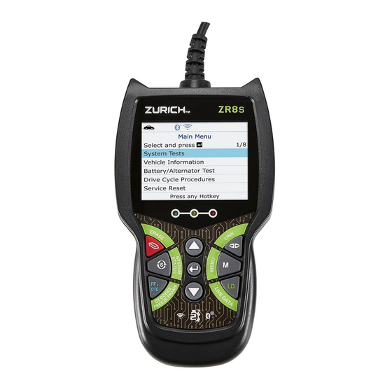
- Page 4 Scan Tool Controls CONTROLS AND INDICATORS CONTROLS AND INDICATORS CONTROLS AND INDICATORS Figure 1. Controls and Indicators See Figure 1 for the locations of items 1 through 14, below. ERASE button - Erases Diagnostic Trouble Codes (DTCs), and “Freeze Frame” data from your vehicle’s computer, and resets Monitor status.
- Page 5 Scan Tool Controls DISPLAY FUNCTIONS DISPLAY FUNCTIONS 5. M button – When pressed, displays the Main Menu. 6. LD button – When pressed while linked to a vehicle, places the Scan Tool in Live Data mode. UP button – When in MENU mode, scrolls UP through the menu options.
- Page 6 Scan Tool Controls DISPLAY FUNCTIONS DISPLAY FUNCTIONS 1. I/M MONITOR STATUS field - Identifies the I/M Monitor status area. 2. Monitor icons - Indicate which Monitors are supported by the vehicle under test, and whether or not the associated Monitor has run its diagnostic testing (Monitor status).
- Page 7 Scan Tool Controls INITIAL ADJUSTMENTS INITIAL ADJUSTMENTS 13. Severity - Indicates the level of severity for the priority code (code number “1”), as follows: 1 - Service should be scheduled and repairs made when convenient. This DTC typically has no immediate threat to essential system components in the short term.
- Page 8 Using the Scan Tool CODE RETRIEVAL PROCEDURE CODE RETRIEVAL PROCEDURE CODE RETRIEVAL PROCEDURE Retrieving and using Diagnostic Trouble Codes (DTCs) for troubleshooting vehicle operation is only one part of an overall diagnostic strategy. Never replace a part based only on the DTC definition. Each DTC has a set of testing procedures, instructions and flow charts that must be followed to confirm the location of the problem.
- Page 9 Using the Scan Tool CODE RETRIEVAL PROCEDURE CODE RETRIEVAL PROCEDURE 6. The Scan Tool automatically starts a check of the vehicle’s computer to determine which type of communication protocol it is using. When the Scan Tool identifies the computer’s communication protocol, a communication link is established.
- Page 10 Using the Scan Tool CODE RETRIEVAL PROCEDURE CODE RETRIEVAL PROCEDURE To select a new vehicle, select New Vehicle, then press ENTER Proceed to step 9. 9. When New Vehicle is chosen from the Select Vehicle screen, the Select Year screen displays. Select the desired vehicle model year, then press ENTER continue.
- Page 11 Using the Scan Tool CODE RETRIEVAL PROCEDURE CODE RETRIEVAL PROCEDURE 11. Refer to DISPLAY FUNCTIONS on page 3 for a description of display elements. In the case of long code definitions, a small arrow is shown in the upper/lower right-hand corner of the Scan Tool display area to indicate presence additional...
- Page 12 Using the Scan Tool CODE RETRIEVAL PROCEDURE CODE RETRIEVAL PROCEDURE Red LED – Indicates there is a problem with one or more of the vehicle’s systems. The red LED is also used to indicate that DTC(s) are present. In this case, the Malfunction Indicator (Check Engine) lamp on the vehicle’s instrument panel will be illuminated.
- Page 13 Using the Scan Tool SYSTEM MENU - ENHANCED DTCs THE SYSTEM MENU - VIEWING OEM ENHANCED DTCs (except Ford/Mazda) THE SYSTEM MENU The System Menu provides the ability to retrieve “enhanced” DTCs, Anti- Lock Brake System (ABS) and Supplemental Restraint System (SRS) DTCs for most BMW, Chrysler/Jeep, Ford/Mazda, GM/Isuzu, Honda/Acura, Hyundai, Mercedes Benz, Nissan, Toyota/Lexus, Volkswagen and Volvo vehicles.
- Page 14 Using the Scan Tool ENHANCED DTCs (FORD / MAZDA ONLY) VIEWING OEM ENHANCED DTCs (Ford/Mazda only) 2. Refer to DISPLAY FUNCTIONS on page 2 for a description of LCD display elements. If the definition for the currently displayed code is not available, an advisory message shows.
- Page 15 Using the Scan Tool ENHANCED DTCs (FORD / MAZDA ONLY) VIEWING OEM ENHANCED DTCs (Ford/Mazda only) Turn the ignition OFF, then back ON. Press ENTER Proceed to step 3. 3. A “One moment please” message displays while the test is in progress. If the Scan Tool fails to link to the vehicle’s computer, a “Communication Error”...
- Page 16 Using the Scan Tool ABS DTCs VIEWING ABS DTCs If no codes are present, a “System Pass” message is displays. Press any Hotkey. 6. If more than one code was retrieved press DTC/FF to display additional codes one at a time. 7.
- Page 17 Using the Scan Tool SRS DTCs VIEWING SRS DTCs If the definition for the currently displayed code is not available, an advisory message shows. I/M MONITOR STATUS icons displayed when viewing ABS DTCs. In the case of long code definitions, a small arrow is shown in the upper/lower right-hand corner of the code display area to indicate the presence of additional information.
- Page 18 Using the Scan Tool NETWORK TEST NETWORK TEST If the Scan Tool cannot link to the vehicle’s computer after three attempts, the message “Contact Technical Support” displays. - Press SYSTEM MENU to return to the System Menu. - Turn the ignition off, and disconnect the Scan Tool. - Contact Technical Support for assistance.
- Page 19 Using the Scan Tool NETWORK TEST NETWORK TEST DTCs recorded for each available module. 2. Select the module for which you wish to view DTCs, then press ENTER . A “One moment please” message displays while the requested DTCs are retrieved. If the Scan Tool fails to link to the selected module, a “Communication Error”...
- Page 20 Using the Scan Tool NETWORK TEST NETWORK TEST To scan a selected module: 1. Choose Select Modules from the System Menu, then press ENTER If the Select Group screen displays, select the group (Drive, Chassis, Body, etc.) containing the module you wish to scan, then press ENTER .
- Page 21 Using the Scan Tool ERASING DIAGNOSTIC TROUBLE CODES (DTCs) ERASING DIAGNOSTIC TROUBLE CODES (DTCs) 5. If more than one code was retrieved press DTC/FF to display additional codes one at a time. Whenever the Scroll function is used, the Scan Tool’s communication link with the vehicle’s computer disconnects.
- Page 22 Using the Scan Tool ABOUT REPAIRSOLUTIONS® ABOUT REPAIRSOLUTIONS® If you do not want to proceed, select No, then press ENTER to cancel the erase procedure. 4. If you chose to erase DTCs, a “One moment please…” message displays while the erase function is in progress. If the vehicle’s engine is running, an advisory message shows.
-
Page 23: Limited 90 Day Warranty
Using the Scan Tool CONNECTING TO BLUETOOTH / WIFI CONNECTING TO BLUETOOTH / WIFI Video Tutorials – Watch repair video tutorials for valuable repair tips. Technical Service Bulletins – Research known problems reported by vehicle manufacturers. Safety Recalls – Research known safety concerns applicable to a vehicle. - Page 24 Using the Scan Tool CONNECTING TO BLUETOOTH / WIFI CONNECTING TO BLUETOOTH / WIFI You can automatically connect to the network your Smart Device is currently connected to, or you can manually connect to another available network. Note that only 2.4GHz networks are supported. If you do not wish to connect to a WiFi network at this time, tap SKIP.
- Page 25 Live Data Mode LIVE DATA MODE - VIEWING LIVE DATA VIEWING LIVE DATA The Scan Tool lets you view and/or "capture" (record) "real-time" Live Data. This information includes values (volts, rpm, temperature, speed etc.) and system status information (open loop, closed loop, fuel system status, etc.) generated by the various vehicle sensors, switches and actuators.
-
Page 26: Customizing Live Data (Pids)
Live Data Mode CUSTOMIZING LIVE DATA (PIDs) CUSTOMIZING LIVE DATA (PIDs) If communication with the vehicle is lost while viewing Live Data, a Communication Lost" message shows on the Scan Tool's display. 5. Press and release ENTER to view the currently selected PID in “graph” mode. Press and release ENTER again to return to the PID list. -
Page 27: Recording (Capturing) Live Data
Live Data Mode RECORDING (CAPTURING) LIVE DATA RECORDING (CAPTURING) LIVE DATA If Live Data is not supported by the vehicle under test, an advisory message displays. Press SYSTEM MENU to return to the System Menu. If custom Live Data was previously configured, the Select PIDs to Use screen displays. - Page 28 Live Data Mode RECORDING (CAPTURING) LIVE DATA RECORDING (CAPTURING) LIVE DATA Record by DTC Trigger This function automatically records Live Data information when a DTC sets and saves it in the Scan Tool’s memory. The recorded data can be a valuable troubleshooting aid, particularly if you are experiencing a fault that is causing a DTC to set.
- Page 29 Live Data Mode RECORDING (CAPTURING) LIVE DATA RECORDING (CAPTURING) LIVE DATA - To retry the erase process, verify that the Scan Tool is properly connected to the vehicle’s DLC and that the ignition is on. Select Erase, then press ENTER - To exit the record function, select Back, then press ENTER to return to the Record Live Data menu.
-
Page 30: Live Data Playback
Live Data Mode LIVE DATA PLAYBACK LIVE DATA PLAYBACK The Select PIDs to Record screen displays. 4. Press UP and DOWN to scroll through the available PIDs. When a PID you wish to record is highlighted, press ENTER (a “checkmark” shows to confirm your selection). - Page 31 Live Data Mode LIVE DATA PLAYBACK LIVE DATA PLAYBACK When you select Yes from the Record Live Data confirmation screen, the Scan Tool enters the "Live Data Playback" mode, and the Playback Live Data menu displays. 3. Select Continuous Playback or Frame by Frame, as desired, then press ENTER The display shows the recorded Live...
- Page 32 Additional Tests ADDITIONAL TESTS - SYSTEM TEST MENU SYSTEM TEST MENU In addition to retrieving Diagnostic Trouble Codes (DTCs), you can use the Scan Tool to perform additional diagnostic tests, to view diagnostic and vehicle information stored in your vehicle's on-board computer, and to configure the Scan Tool for your particular needs.
-
Page 33: System Test Menu
Additional Tests SYSTEM TEST MENU SYSTEM TEST MENU The Main Menu displays. 2. Select System Tests, then press ENTER The System Test menu displays. If System Tests is not shown on the Main Menu, the System Tests functions available for your vehicle. O2 Sensor Test OBD2 regulations require that applicable vehicles monitor and test operation of the oxygen (O2) sensors to identify problems that can affect fuel... - Page 34 Additional Tests SYSTEM TEST MENU SYSTEM TEST MENU 6. When you have finished viewing test data for all desired sensors, select Back, then press ENTER to return to the System Test menu; or, press M to return to the Main Menu. OBD Monitor Test The OBD Monitor Test function retrieves and displays test results for emission-related powertrain components and systems that are not...
-
Page 35: Resetting The Oil Maintenance Light
Additional Tests RESETTING OIL MAINTENANCE LIGHT RESETTING THE OIL MAINTENANCE LIGHT EVAP Test The EVAP Test function lets you initiate a leak test for the vehicle's EVAP system. The Scan Tool does not perform the leak test, but signals to vehicle's on-board computer to initiate the test. -
Page 36: Battery Reset
Additional Tests BATTERY RESET BATTERY RESET If the Scan Tool cannot reset the Oil Maintenance Light, an “instructional” dialog displays, showing the manual procedures for resetting the indicator light. When finished viewing the instructions, press M to return to the Main Menu. 4. - Page 37 Additional Tests BATTERY RESET BATTERY RESET If battery reset procedures are not available for your vehicle, an advisory message shows. Press M to return to the Main Menu. 4. Select the procedure you wish to view, then press ENTER The selected procedure displays. 5.
-
Page 38: Performing A Service Check
Additional Tests SERVICE CHECK - BATTERY/ALTERNATOR TEST PERFORMING A SERVICE CHECK - BATTERY/ALTERNATOR TEST PERFORMING A SERVICE CHECK The Service Check function lets you check the current oil level and oil life. 1. While linked to the vehicle, press M. The Main Menu displays. - Page 39 Additional Tests BATTERY/ALTERNATOR TEST BATTERY/ALTERNATOR TEST Turn the ignition on. DO NOT start the engine. 5. Press ENTER to begin the battery check. If the engine is running, an advisory message shows. Turn the engine off, then turn the ignition on. DO NOT start the engine.
- Page 40 Additional Tests BATTERY/ALTERNATOR TEST BATTERY/ALTERNATOR TEST 3. Select Alternator Test, then press ENTER An “instructional” message shows. 4. Start and warm the engine to normal operating temperature. Turn on the headlights. Press ENTER to continue. An “instructional” message shows. 5. Press the accelerator pedal to raise engine speed to 2000 RPM, and maintain the engine speed.
-
Page 41: Viewing Drive Cycle Procedures
Additional Tests VIEWING DRIVE CYCLE PROCEDURES VIEWING TRIP CYCLE PROCEDURES If the vehicle supports battery Live Data, the Battery Live Data screen displays. The screen shows the state of charge, battery pack voltage and sum of cell voltages for the battery pack. -
Page 42: Using Dlc Locator
Additional Tests USING DLC LOCATOR USING THE DLC LOCATOR 5. Select the Monitor for which you wish to view Drive Cycle Procedures, then press ENTER A “One moment please…” message displays while the Scan Tool retrieves the requested Drive Cycle Procedure. The Drive Cycle Procedures screen for the Monitor displays when the procedure has been retrieved. -
Page 43: Viewing Vehicle Information
Additional Tests VIEWING VEHICLE INFORMATION VIEWING VEHICLE INFORMATION VIEWING VEHICLE INFORMATION The Vehicle Information function offers three options retrieving reference information for the vehicle under test; Vehicle ID, Available Modules and IPT (In-Use Performance Tracking). Retrieving Vehicle ID Information The Vehicle ID function is applicable to model year 2000 and newer OBD2-compliant vehicles. -
Page 44: Viewing The Firmware Version
Additional Tests VIEWING FIRMWARE VERSION THE TOOL LIBRARY 2. Select Vehicle Information, then press ENTER Vehicle Information menu displays. 3. Select Available Modules, then press ENTER 4. When the retrieval process is completed, a complete list of modules supported by the vehicle under test displays. -
Page 45: The Tool Library
Additional Tests TOOL LIBRARY THE TOOL LIBRARY The Firmware Version screen displays for four seconds. The screen shows the Scan Tool’s current firmware version, bootloader version and database version. 2. The display returns to the Main Menu. THE TOOL LIBRARY The Tool Library contains valuable reference information for the Scan Tool. - Page 46 Additional Tests TOOL LIBRARY THE TOOL LIBRARY Using the DTC Library 1. From the Tool Library menu, select DTC Library, then press ENTER The Select Library screen displays. 2. Select OBD2 Library, then press ENTER The Select Manufacturer screen displays. 3.
-
Page 47: Adjustments And Settings
Additional Tests ADJUSTMENTS AND SETTINGS ADJUSTMENTS AND SETTINGS The screen provides a description of the meanings of the green, yellow and red SYSTEM STATUS LEDs. 2. When you have finished viewing the LED meanings, press M to return to the Main Menu. ADJUSTMENTS AND SETTINGS The Scan Tool lets you make several adjustments and settings to configure the Scan Tool to your particular needs. - Page 48 Additional Tests ADJUSTMENTS AND SETTINGS ADJUSTMENTS AND SETTINGS Enabling/Disabling the Audible Tone 1. Select Audible Tone in the Tool Settings menu, then press ENTER The Audible Tone screen displays. 2. Select On or Off as desired, then press ENTER to save your changes. To return to the Tool Settings menu without making changes, press M.
- Page 49 Additional Tests ADJUSTMENTS AND SETTINGS ADJUSTMENTS AND SETTINGS Setting the Unit of Measurement 1. Select Unit of Measurement in the Tool Settings menu, then press ENTER The Unit of Measurement screen displays. 2. Select the desired unit of measurement, Save then choose save...
- Page 50 Notes Notes TITLE NOTES Record Product’s Serial Number Here: Note: If product has no serial number, record month and year of purchase instead. Note: Replacement parts, other than cable, are not available. Reference UPC 193175420848. For technical questions, please call 1-888-866-5797...
-
Page 51: Warranty And Servicing
Warranty and Servicing WARRANTY AND SERVICE PROCEDURES TITLE , ,&% ! ! # ! #))#.& ! HE\DE!+E?WXZC!'DDL=!0D.!]H`?=!?Y?EM!?__DEC!CD!H==[E?!CZHC!WC=!BEDF[AC=! ]??C!ZWXZ!b[HLWCM!HKF!F[EH\WLWCM!=CHKFHEF=V!HKF!^HEEHKC=!CD!CZ?!DEWXWKHL! B[EAZH=?E! CZHC! CZW=! BEDF[AC! W=! _E??! _ED]! F?_?AC=! WK! ]HC?EWHL=! HKF! ^DE`]HK=ZWB!_DE!CZ?!B?EWDF!D_! !FHM=!_ED]!CZ?!FHC?!D_!B[EAZH=?.!'ZW=! ^HEEHKCM!FD?=!KDC!HBBLM!CD!FH]HX?!F[?!FWE?ACLM!DE!WKFWE?ACLMV!CD!]W=[=?V! H\[=?V!K?XLWX?KA?!DE!HAAWF?KC=V!E?BHWE=!DE!HLC?EHCWDK=!D[C=WF?!D[E!_HAWLWCW?=V! AEW]WKHL!HACWYWCMV!W]BEDB?E!WK=CHLLHCWDKV!KDE]HL!^?HE!HKF!C?HEV!DE!CD!LHA`!D_! ]HWKC?KHKA?.!;?!=ZHLL!WK!KD!?Y?KC!\?!LWH\L?!_DE!F?HCZV!WKa[EW?=!CD!B?E=DK=! DE! BEDB?ECMV! DE! _DE! WKAWF?KCHLV! ADKCWKX?KCV! =B?AWHL! DE! ADK=?b[?KCWHL! FH]HX?=!HEW=WKX!_ED]!CZ?![=?!D_!D[E!BEDF[AC.!*D]?!=CHC?=!FD!KDC!HLLD^! CZ?!?@AL[=WDK!DE!LW]WCHCWDK!D_!WKAWF?KCHL!DE!ADK=?b[?KCWHL!FH]HX?=V!=D!CZ?! H\DY?!LW]WCHCWDK!D_!?@AL[=WDK!]HM!KDC!HBBLM!CD!MD[.!' "*!;(&&()'-!"*! - Page 52 Distributed by Harbor Freight Tools, Calabasas, CA 57667 Copyright © 2021. All rights reserved.