Table of Contents
Advertisement
Quick Links
MOBILEMESH HANDHELD DOCUMENTATION
LAST UPDATE 11/6/21
INTRODUCTION
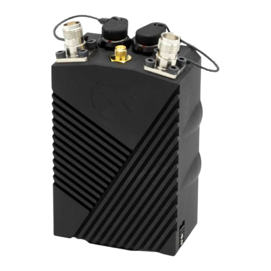
The MobileMesh Radio by Horizon31 is a rugged mobile radio node utilizing the Doodle Labs™ meshing Smart
Radio module. Based on 2×2 MIMO technology, the MobileMesh Radio can achieve a range of 20 km and
throughput of up to 100 Mbps. The MobileMesh radio is ideally suited as the ground control station radio in
unmanned systems applications. It can be connected to a computing device using USB-A, USB-C or Ethernet and
will provide high-bandwidth IP interconnectivity and advanced ad-hoc meshing.
Unique in its class, the MobileMesh radio includes an optional Real-Time Kinematic (RTK) GPS and can be used as
an RTK base station, providing up to centimeter-level positional accuracy.
Advertisement
Table of Contents

Summary of Contents for Horizon Fitness MobileMesh
- Page 1 Radio module. Based on 2×2 MIMO technology, the MobileMesh Radio can achieve a range of 20 km and throughput of up to 100 Mbps. The MobileMesh radio is ideally suited as the ground control station radio in unmanned systems applications. It can be connected to a computing device using USB-A, USB-C or Ethernet and will provide high-bandwidth IP interconnectivity and advanced ad-hoc meshing.
- Page 2 COMPLIANCE AND ORIGIN The MobileMesh radio is designed, manufactured and supported in the United States. The radio technology used inside the radio is developed by Doodle Labs, who has a presence in the United States and Singapore. There is no network connectivity or data storage located outside the United States, or administered by any entity domiciled in an adversary country.
- Page 3 We do not recommend powering the MobileMesh without antennas attached. 3. Power on the MobileMesh Radio: Momentarily depress the power switch on the side of the MobileMesh. The Battery and Status LEDS should come on to let you know power is on.
-
Page 4: Powering On And Off
The power on, momentary depress the power button To power off, push and hold the power button for several seconds until you see both LEDs turn off. LED INDICATORS The MobileMesh radio has two LED indicators, Battery (BATT) and STATUS. The function of each is explained below:... -
Page 5: Internal Gps
To enable Tactical mode, Using the web UI, enable Advanced Settings, then System > LED Control set “LED Tactical Mode” on (checked) to enable this feature. INTERNAL GPS Some models of the MobileMesh include an RTK GPS module inside. If included, the user can access this GPS in three ways: Via the host computer Using cables H31-MM-CAB-USBA-MALE or H31-MM-CAB-USBC-MALE, the uBlox NEO-M8P GPS will enumerate as a USB device when either of these cables are plugged into the host device. -
Page 6: Using Peripherals
USING PERIPHERALS The MobileMesh radio’s Auxiliary connector is typically used as a passthrough USB device. When primary USB cables H31-MM-CAB-USBA-MALE or H31-MM-CAB-USBC-MALE are used, pins 1-4 on the auxiliary connector provide an additional USB passthrough from the host device. This can be beneficial to organize wiring, or remove the need for an external USB hub in cases where the host device may only have a single USB port (e.g., phones or... - Page 7 Figure 1. Primary pinout (Pin side) Pin Number Function Direction Notes USB_CC Only used for USB-C ETH_RX- 100 Mbps Ethernet ETH_RX+ 100 Mbps Ethernet ETH_TX+ 100 Mbps Ethernet GPIO...
- Page 8 Pin Number Function Direction Notes VBUS USB D- BIDIR USB D+ BIDIR ETH_TX- 100 Mbps Ethernet TIMEPULSE Custom cables are available, or blunt-cut cables ( ) can be ordered for custom H31-MM-CAB-PRI-BLUNT connectivity options. AUXILLARY CONNECTOR The connector is ODU G81YAR-P08UF00-000L The mating connector is ODU S11YAR-P08XFG0-0000...
- Page 9 Figure 2. Auxiliary Pinout (Pin side) Pin Number Function Direction Notes VBUS Passthrough USB from host device This USB connection is a downstream port USB D- BIDIR of a hub, connected to the host computer connected Via the Primary ODU USD interface. This USB connection is a downstream port USB D+ BIDIR...
-
Page 10: Updating The Firmware
UPDATING THE FIRMWARE The MobileMesh radio uses stock Doodle Labs firmware, and you can update it as needed using firmware provided by Doodle Labs. However, we do overlay additional scripts and files to support the “status” LED functions and to share RSSI data with a connected ground control system. -
Page 11: Factory Reset
10.223.x.y where x.y is the last four hexadecimal digits of the wireless MAC address converted to decimal. For example, a MobileMesh with MAC 0x00:30:1A:4E:7A:B0 has the last four HEX digits 7AB0 and so x.y is equal to 122.176 since 0x7A=122 and 0xB0=176. This full IP address in this case would be 10.223.122.176. - Page 12 LED status for battery level Mechanical: 4.1 x 2.8 x 1.6 in (excluding battery) 14.5 oz (excluding battery/antenna) STEP file available upon request/NDA Environmental: Temperature: -40°C to +85°C Humidity 0-95% non-condensing IP67 (pending formal testing) Security: AES-256 FIPS-Level 2 Compliant NSA Suite B Available Interfaces: Primary: USB or Ethernet, ODU AMC Connector...