
Related Manuals for Omega FDT-25W


Summary of Contents for Omega FDT-25W
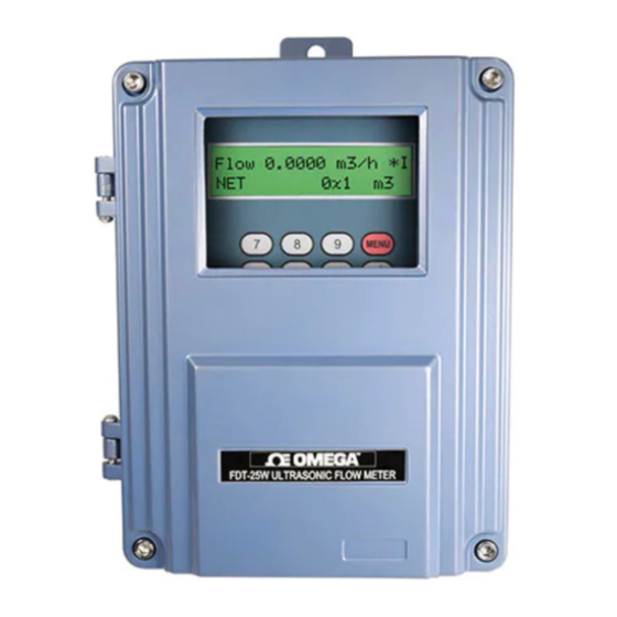
- Page 1 User’s Guide Shop online at omega.com e-mail: info@omega.com For latest product manuals: omega.com/en-us/pdf-manuals omega.com/en-us/pdf-manuals FDT- - - 2 2 2 5 5 5 W W W Wall Mounter Ultrasonic Flowmeter...
- Page 2 Engineering Service: 1-800-872-9436 (USA & Canada only) Tel: (203) 359-1660 Fax: (203) 359-7700 e-mail: info@omega.com The information contained in this document is believed to be correct, but OMEGA accepts no liability for any errors it contains, and reserves the right to alter specifications without notice.
-
Page 3: Table Of Contents
FDT-25W Wall Mounter Ultrasonic Flowmeter Wall Mounter Ultrasonic Flow Meter User Manual Contents 1. Introduction................................3 1.1 Preface................................3 1.2 Features..............................3 1.3 Flow measurement principle........................3 1.4 Optional transducer..........................4 1.5 Typical application............................ 4 1.6 Product Identification..........................5 1.7 Specifications.............................5 2. Installation and Measurement...........................6 2.1 Dimension.............................. - Page 4 FDT-25W Wall Mounter Ultrasonic Flowmeter 4.19 How to use the OCT output........................ 30 4.20 How to modify the built-in calendar....................30 4.21 How to view the Date Totalizers......................30 4.22 How to use the Working Timer......................30 4.23 How to use the manual totalizer......................30 4.24 How to know how long the battery will last..................
-
Page 5: Introduction
◆ 1.3 Flow measurement principle The FDT-25W ultrasonic flow meter is designed to measure the fluid velocity of liquid within a closed conduit. The transducers are a non-contacting, clamp-on type, which will provide benefits of non-fouling operation and easy installation. -
Page 6: Optional Transducer
FDT-25W Wall Mounter Ultrasonic Flowmeter Downstream transducer flow Tdown down θ Upstream transducer spacing Where θ is the include angle to the flow direction M is the travel times of the ultrasonic beam D is the pipe diameter... -
Page 7: Product Identification
FDT-25W Wall Mounter Ultrasonic Flowmeter 1.6 Product Identification Each set of the flow meter has a unique product identification number or ESN (electronic serial number) written into software that only be modified with a special tool by the manufacturer. In case of any hardware failure, please provide this number which is located on menu window M61 when contacting the manufacturer. -
Page 8: Installation And Measurement
FDT-25W Wall Mounter Ultrasonic Flowmeter Transducer: standard is IP65, IP68(optional) Twisted Pair Line, standard length of 20m, can be extended to 500m Cable (not recommended); Contact the manufacturer for longer cable requirement. RS-485 interface, transmission distance up to 1000m Power Supply AC220V or DC24V Power Less than 1.5W... -
Page 9: Wiring
FDT-25W Wall Mounter Ultrasonic Flowmeter 2.2 Wiring 2.3 Keypad The keypad for the operation of the flow meter is as shown by the right picture. Keys are keys to enter numbers Key ▲/+ is the going UP key, when the user wants to go to the upper menu window. -
Page 10: Menu Windows
FDT-25W Wall Mounter Ultrasonic Flowmeter Key ▼/- is the going DOWN key, when the user wants to go down-sided menu window. It also works as the “–” key when entering numbers. ◄ is backspace key, when the user wants go left or wants backspace the left character that is located to the left of the cursor. -
Page 11: Steps To Configure The Parameters
FDT-25W Wall Mounter Ultrasonic Flowmeter Generally, the ENT key must be pressed to enter a modification mode. If the “Locked M47 Open’ message is indicated on the lowest line of the LCD display, it means the modification operations is locked out. In such cases, the user should go to M47 to have the instrument unlocked first before any further modification can be made. -
Page 12: Transducers Mounting Allocation
FDT-25W Wall Mounter Ultrasonic Flowmeter (11) Press MENU to check up signal strength and quality, the bigger of the value the better. Generally the signal strength should be better than 60.0, and signal quality should be better than 50.0. (12) Press MENU to check up time ratio, the ratio value should be in the range of 100±3%... -
Page 13: Transducers Installation
2.7 Transducers Installation The transducers used by the FDT-25W series ultrasonic flow meter are made of piezoelectric crystals both for transmitting and receiving ultrasonic signals through the wall of liquid piping system. The measurement is realized by measuring the traveling time difference of the ultrasonic signals. Since the difference is very small, the spacing and the alignment of the transducers are critical factors to the accuracy of the measurement and the performance of the system. - Page 14 FDT-25W Wall Mounter Ultrasonic Flowmeter 2.7.1 Wiring diagram of transducer 2.7.2 Transducers Spacing The spacing value shown on menu window M25 refers to the distance of inner spacing between the two transducers. The actual transducers spacing should be as close as possible to the spacing value.
- Page 15 FDT-25W Wall Mounter Ultrasonic Flowmeter 2.7.4 Z-method Installation Z-method is commonly used when the pipe diameter is above 200mm. 2.7.5 W-method Installation W-method is usually used on pipes with a diameter from 15mm to 50mm.
-
Page 16: Installation Checkup
FDT-25W Wall Mounter Ultrasonic Flowmeter 2.7.6 N-method Installation Rarely used method. 2.8 Installation Checkup Through the checkup of the installation, one can: check the receiving signal strength, the signal quality Q value, the traveling time difference of the signals, the estimated liquid speed, the measured traveling time of the signals and the calculated traveling time ratio. -
Page 17: Menu Window Details
FDT-25W Wall Mounter Ultrasonic Flowmeter 2.8.2 Signal quality Signal quality is indicated as the Q value in the instrument. A higher Q value would mean a higher Signal and Noise Ratio (short for SNR), and accordingly a higher degree of accuracy would be achieved. -
Page 18: Menu Window Details
FDT-25W Wall Mounter Ultrasonic Flowmeter window for viewing date totalizer. M90~M94 are diagnostic windows for a more accurate measurement. M97~M99 are not windows but commands for the outputting of display copying and pipe parameter setups. M+0~M+8 are windows for some additional functions, including a scientific calculator, viewer on records such as total working hours, turn-on and turn-off times, dates and times when the flow meter has been turned on or turned off. - Page 19 FDT-25W Wall Mounter Ultrasonic Flowmeter Window for entering pipe wall thickness You may skip the menu and enter inner diameter in M13 instead. Window for entering the inner diameter of the pipe If pipe outer diameter and wall thickness are enter correctly, the inner diameter will be...
- Page 20 FDT-25W Wall Mounter Ultrasonic Flowmeter regarded as empty pipe, and the flow meter will not totalize flow. This is based on the fact that, for most occasions, when pipe is empty, the transducer would still receive signal, just smaller than normal, As a result, The flow meter would show normal operation, which is not correct.
- Page 21 FDT-25W Wall Mounter Ultrasonic Flowmeter Flow rate scale factor. The default value is ‘1’. Keep this value as ‘1’, when no calibration has been made. Networks address identification number. Any integer can be entered except 13(0DH, carriage return), 10 (0AH, line feeding), 42 (2AH), 38, 65535.
- Page 22 FDT-25W Wall Mounter Ultrasonic Flowmeter Check if the current loop is calibrated correctly. Display the present output current of current loop circuit. Setup system date and time. Press ENT for modification. Use the dot key to skip the digits that need no modification.
- Page 23 FDT-25W Wall Mounter Ultrasonic Flowmeter Window to setup the lower limit of flow rate for Alarm#2. Window to setup the upper limit of flow rate for Alarm#2. Buzzer setup. If a proper input source is selected, the buzzer will beep when the trigger event occurs. The available trigger sources are: 0.
- Page 24 FDT-25W Wall Mounter Ultrasonic Flowmeter The RELAY is of SPST(Single pole, single throw) type. It is rated for 110VAC max and have a current rating of 0.5A resistive load. It highly recommended that a salve relay to be utilized whenever a large resistive load or inductive load is to be controlled.
- Page 25 FDT-25W Wall Mounter Ultrasonic Flowmeter the one after going on line. Set the thermal energy unit: 0. GJ 1. KC 2.KWh 3. BTU Select temperature sources from T1,T2 (factory default) from AI3,AI4 Select the Specific Heat Value. Factory default is ‘GB’. Under this setting, the flow meter will calculate the enthalpy of water based on the international standard.
- Page 26 FDT-25W Wall Mounter Ultrasonic Flowmeter When the backup battery is removed, the total working time will be reset to zero. Displays the last power-off date and time Displays the last power-off flow rate Displays how many times of has been powered on and powered off.
-
Page 27: How To
FDT-25W Wall Mounter Ultrasonic Flowmeter 4. How To 4.1 How to judge if the instrument works properly Enter into M08, if ‘R’ is displayed on the screen, the instrument is working properly, If 'E' is displayed, the current loop output is over-ranged. Increasing the range setting in M57 will make the 'E' letter disappear. -
Page 28: How To Use The Totalizer Multiplier
FDT-25W Wall Mounter Ultrasonic Flowmeter 4.5 How to use the totalizer multiplier Use window M33 to select a proper totalizer. Make sure that the totalizer pulse is appropriately speeded. It should not be too fast and neither too slow. A speed of producing a pulse in several seconds or minutes is preferable. -
Page 29: How To Setup A Zero Point
FDT-25W Wall Mounter Ultrasonic Flowmeter Generally the default value is 0.03m/s The low-cutoff value does not affect the flow measurement when the actual flow is absolutely greater than the low-cutoff value. 4.11 How to setup a zero point There exists a ‘Zero Point’ with certain installation which means the flow meter will display a non-zero value when the flow is absolutely stopped. -
Page 30: How To Use The Frequency Output
The present current loop output is displayed in Window M59. It changes along with flow rate change. 4.15 How to use the Frequency Output There is a Frequency Output in all FDT-25W series flow meters. This frequency output signal, which represents the flow rate, is intended to connect with other instruments. -
Page 31: How To Produce An Alarm Signal
FDT-25W Wall Mounter Ultrasonic Flowmeter The totalizer output will produce a pulse output with every unit flow of the totalizer. The totalizer pulse output can only be realized by mapping the pulse output to the OCT or BUZZER hardware devices. -
Page 32: How To Use The Built-In Buzzer
FDT-25W Wall Mounter Ultrasonic Flowmeter (3) Enter flow rate lower limit 600 in M75 (4) Enter flow rate lower limit 1000 in M76 (5) Select item '6. Alarm #1' in M78 (6) Select item '6. Alarm #1' in M79. 4.18 How to use the built-in Buzzer The built-in buzzer is user-configurable. -
Page 33: How To Know How Long The Battery Will Last
4.25 How to check the ESN and other minor details Every set of the FDT-25W flow meter utilizes a unique ESN to identify the meter. The ESN is an 8-digit number that provides the information of version and manufacturing date. -
Page 34: How To Use Automatic Amending Function For Offline Compensation
4.33 How to solidify the parameters There are three kinds of parameters for the new generation FDT-25W: 1) Current parameters, the parameters are stored in the RAM. They will be lost when one cut the power or remove the reserve battery. -
Page 35: How To Use The Circular Display Function
FDT-25W Wall Mounter Ultrasonic Flowmeter user-type-wedge parameters that describe the user transducers. If the PI-type transducer is selected, you need enter additional 4 PI-type transducer parameters that describe the PI-type transducers. 4.35 How to use the circular display function When entering menu window 95, the circular display function will be started automatically. The following windows will be displayed one by one, each window will stay for 8 seconds: M95>>M00>>M01>>M02>>M02>>... -
Page 36: How To Save / Restore Frequently-Used Pipe Parameters
5. Troubleshooting 5.1 Power-on Error Displays and Counter-Measures The FDT-25W ultrasonic flow meter provides an automatic power-on diagnosis for the hardware problems. When any message (with the power on) in the following table displays, counter-measures should be taken. -
Page 37: Error Code And Counter-Measures
5.2 Error Code and Counter-Measures The FDT-25W ultrasonic flow meter will show Error Code in the lower right corner with a single letter like I, R etc. on menu windows M00, M01, M02, M03, M90 and M08. When any abnormal Error Code shows, counter-measures should be taken. -
Page 38: Other Problems And Solutions
FDT-25W Wall Mounter Ultrasonic Flowmeter 5.3 Other Problems and Solutions 1. When the actual flow inside the pipe is not standstill, but the instrument displays 0.0000 for the flow rate, and ‘R’ displaying signal strength and the signal quality Q (value) has a satisfactory value? The problems are likely caused by the user who has used the ‘Set Zero’... - Page 39 Department will issue an Authorized Return (AR) number immediately upon phone or written request. Upon examination by OMEGA, if the unit is found to be defective, it will be repaired or replaced at no charge. OMEGA’s WARRANTY does not apply to defects resulting from any action of the purchaser, including but not limited to mishandling, improper interfacing, operation outside of design limits, improper repair, or unauthorized modification.
- Page 40 Where Do I Find Everything I Need for Process Measurement and Control? OMEGA…Of Course! Shop online at omega.com TEMPERATURE M U Thermocouple, RTD & Thermistor Probes, Connectors, Panels & Assemblies M U Wire: Thermocouple, RTD & Thermistor M U Calibrators & Ice Point References M U Recorders, Controllers &...