Advertisement
Quick Links
WHAT IS THE Honeywell OmniProx™ READER?
The
Reader is an RFID proximity card reader to
OmniProx
be installed for use with access control systems.
These installation instructions contain the following
information:
•
Mounting Instructions
•
Connecting the reader to the host
•
Testing and operation of the reader
Visit www.omniprox.com for the latest information and
technical support.
HOW TO MOUNT THE READER
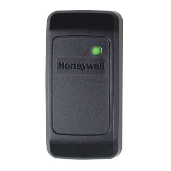
Figure 1 shows the front view of the OmniProx. When
mounting models OP10/20/30/40/45, the snap-off cover
must be removed to access the screw holes.
®
The model OP90 uses a security screw on the bottom of the
reader to secure the cover. Remove this security screw
using the supplied tool. Then slide the back plate down
slightly and then lift it up from the bottom. Select the
desired mounting holes and drill them out.
Mount the reader with the appropriate screws (not
supplied) as indicated on the template.
To surface mount the reader, perform the following:
1.
Determine an appropriate mounting position for the
reader.
2.
Peel off the back of the self-stick mounting label
template included with the unit and place at the
desired mounting position. (Additional templates can
be downloaded from www.omniprox.com.)
3.
Using the template as a guide, drill two holes (hole size
is indicated on mounting template) for mounting the
reader to the surface.
4.
Drill a 1/2" (13 mm) hole for the cable. If mounting on
metal, place a grommet or electrical tape around the
edge of the hole.
5.
Route the interface cable from the reader and/or power
supply to the host. A linear type power supply is
recommended.
Installation Instructions
Figure 1
SNAP ON/OFF TOP COVERS:
Hides mounting screws
and protects the reader
Model Series OP10/20/30/40/45/90
Check all electrical codes for proper installation.
Card Reader Models OP10/20/30/40/45/90 are to be
U L
used with control panels whose power supply is UL
listed Class 2 or equivalent.
HOW TO CONNECT THE READER TO THE HOST
The OmniProx Reader is supplied with an 18-inch pigtail,
having a 6-conductor cable. To connect the reader to the
host, perform the following steps:
1.
If there is a connector on the end of the cable (used
during manufacture for testing purposes), cut it off.
Prepare both the reader cable and host cables by
cutting the cable jacket back 1¼ inches and strip the
wires
inch.
½
2. Splice the reader pigtail wires to the corresponding
host wires and cover each connection (see Figure 2).
3. If the tamper output is being utilized, connect the
purple wire to the correct input on the host.
4.
Trim and cover all conductors that are not used.
Figure 2 below shows how you should wire the reader to the
host.
Wiring Notes:
1.
The individual wires coming out of the reader are color
coded according to the recommended Wiegand standard.
2.
If either 5 or 12 volts are available, use 12 volts for better
performance.
3.
When using a separate power supply for the reader, the
reader, power supply and host must have a common ground.
4.
The recommended cable depends on the distance from
the reader to the host. See Table 1 on the next page for
the correct wire gage based upon distance. Larger wire
gauges are acceptable. The wire must be stranded with
an overall shield, either foil or braided. If the tamper is not
being used, 5 conductor cable is required; otherwise 6
conductor cable is required.
5.
The cable shield wire on the reader should be attached to
an Earth ground (best) or signal ground connection at the
panel or power supply end of the cable. This configuration
is best for shielding the reader cable from external
interference.
-1-
OmniProx™ Reader
K5336 Rev. 9, 11-Sep-2003
Figure 2
Advertisement

Summary of Contents for Honeywell OmniTek OmniProx OP10 Series
- Page 1 OmniProx™ Reader Installation Instructions Model Series OP10/20/30/40/45/90 K5336 Rev. 9, 11-Sep-2003 WHAT IS THE Honeywell OmniProx™ READER? Reader is an RFID proximity card reader to OmniProx be installed for use with access control systems. Check all electrical codes for proper installation.
- Page 2 TABLE 1: WIRE GAGE SPECIFICATIONS SPECIFICATIONS Electrical Characteristics: Distance Gage 5 Conductor 6 Conductor Power Supply Type: Linear type Recommended ≤ 200 ft. (61m) Alpha 1295C Alpha 1296C Operating Voltage Range: ≤300 ft. (91m) Alpha 58126 Alpha 58126 5.0 – 16 VDC (Operational down to 4.25 VDC) ≤...
- Page 3 Access Control Proximity Reader Model numbers OP10, OP20, OP30, OP40, OP45, and OP90 File No. BP9666 Acknowledgements: OmniProx is a registered trademark of Honeywell International. Wiegand is a licensed trademark of HID Corp. HID is a licensed trademark of HID Corp.
- Page 4 ADEMCO Limited Warranty Alarm Device Manufacturing Company, a Division of Pittway Corporation, and its divisions, subsidiaries and affiliates ("Seller"), 165 Eileen Way, Syosset, New York 11791, warrants OmniProx products to be in conformance with its own plans and specifications and to be free from defects in materials and workmanship under normal use and service for the life of the product.


