Table of Contents
Advertisement
Quick Links
Advertisement
Table of Contents

Related Manuals for Mitsubishi Electric CC-Link IE TSN FR-A8NCG


Summary of Contents for Mitsubishi Electric CC-Link IE TSN FR-A8NCG
- Page 1 PRE-OPERATION INSTRUCTIONS INVERTER INSTALLATION Plug-in option FR-A8NCG WIRING INSTRUCTION MANUAL CC-LINK IE TSN CONFIGURATION INVERTER SETTING Class B communication function FUNCTION OVERVIEW I/O SIGNAL PROGRAMMING EXAMPLES PROTECTIVE FUNCTIONS...
- Page 2 Thank you for choosing this Mitsubishi Electric inverter plug-in option. This Instruction Manual provides handling information and precautions for use of this product. Incorrect handling might cause an unexpected fault. Before using this product, read all relevant instruction manuals carefully to ensure proper use.
- Page 3 Additional instructions The following instructions must be also followed. If this product is handled incorrectly, it may cause unexpected fault, an injury, or an electric shock. CAUTION Transportation and installation Do not stand or place heavy objects on this product. ...
- Page 4 General instruction For clarity, illustrations in this Instruction Manual may be drawn with covers or safety guards removed. Ensure all covers and safety guards are properly installed prior to starting operation.
-
Page 5: Table Of Contents
─ CONTENTS ─ 1 PRE-OPERATION INSTRUCTIONS Unpacking and product confirmation..........................7 1.1.1 Product confirmation ................................7 1.1.2 Model name ..................................8 1.1.3 SERIAL number check................................8 Parts....................................10 CC-Link IE TSN communication specifications......................12 2 INSTALLATION Pre-installation instructions ............................13 Installation procedure ..............................14 3 WIRING System configuration example.............................18 Network configuration..............................19 Network components ..............................22... - Page 6 List of parameters for the CC-Link IE TSN communication function ...............35 Operation mode setting ..............................36 5.3.1 Operation mode switching and communication startup mode (Pr.79, Pr.340)..............36 Operation at communication error occurrence ......................39 5.4.1 Operation selection at communication error occurrence (Pr.500 to Pr.502, Pr.779) ............39 5.4.2 Fault and measures ................................
- Page 7 7.3.4 Monitor codes ..................................83 Torque command / torque limit through CC-Link IE TSN communication (only for the FR-A800 series) ....84 8 PROGRAMMING EXAMPLES Programming example for reading the inverter status ....................91 Programming example for setting the operation mode .....................92 Programming example for setting the operation commands..................93 Programming example for monitoring the output frequency..................94 Programming example for parameter reading......................95...
-
Page 8: Pre-Operation Instructions
PRE-OPERATION INSTRUCTIONS Unpacking and product confirmation Take the product out of the package, check the product name, and confirm that the product is as you ordered and intact. This product is a plug-in option made for the FR-A800/F800 series. 1.1.1 Product confirmation Check the enclosed items. -
Page 9: Model Name
1.1.2 Model name FR-A8NCG- Symbol Circuit board coating∗1 Without None With Conforming to IEC 60721-3-3 3C2/3S2 1.1.3 SERIAL number check The FR-A8NCG can be used with the following models of inverters which have the following SERIAL number. Check the SERIAL number printed on the rating plate or on the package of the inverter. - Page 10 FR-F800 series Model Country of origin indication SERIAL number FR-F820-00046(0.75K) to 04750(110K) MADE in Japan 96 or later FR-F840-00023(0.75K) to 06830(315K) FR-F842-07700(355K) to 12120(560K) MADE in China 97 or later FR-F846-00023(0.75K) to 03610(160K) PRE-OPERATION INSTRUCTIONS...
-
Page 11: Parts
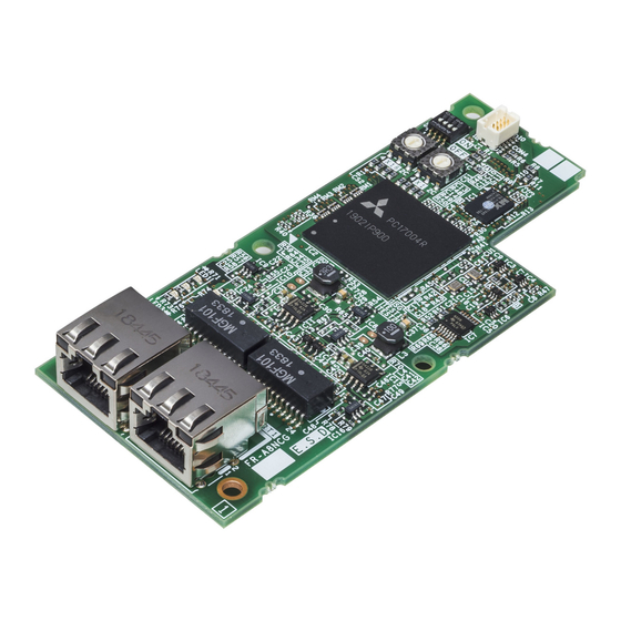
Parts Front view Rear view X16 X1 LINK1 LINK2 L.ERR Refer Symbol Name Description to page Used to fix this product to the inverter by inserting a mounting Mounting hole screw or a spacer. Connector for communication (PORT 1) For an Ethernet cable which connects to the network. Connector for communication (PORT 2) For an Ethernet cable which connects to the network. - Page 12 Operation status LEDs LINK1 LINK2 L.ERR Description Blinking name Normal operation (normal Operation status Hardware failure 5 V internal voltage) Connector for communication (PORT1) LINK1 Link-up Data transmission in progress Link-down status Connector for communication (PORT2) LINK2 Link-up Data transmission in progress Link-down status...
-
Page 13: Cc-Link Ie Tsn Communication Specifications
CC-Link IE TSN communication specifications The communication specification varies depending on the specification of the master. Item Description Transmission speed 1 Gbps/100 Mbps Minimum synchronization cycle 125.00 μs CC-Link IE TSN authentication class Communication method Time sharing method Synchronization function Compliant with IEEE 802.1AS and IEEE 1588v2 Maximum number of connected units 121 units (sum of master and slave stations) -
Page 14: Installation
INSTALLATION Pre-installation instructions Check that the inverter's input power and the control circuit power are both OFF. CAUTION Do not install or remove this product while the inverter power is ON. Doing so may damage the inverter or this product. To avoid damage due to static electricity, static electricity in your body must be discharged before you touch this product. -
Page 15: Installation Procedure
Installation procedure Installing the communication option LED display cover (1) Remove the inverter front cover. (Refer to Chapter 2 of the Instruction Manual (Detailed) of the inverter for instructions for removing the front cover.) Follow instructions for mounting the communication option LED display cover to the inverter front cover. (2) Cut off the tabs on the rear of the inverter front cover with nipper, etc. - Page 16 Installing the option (1) Insert three spacers into the mounting holes that will not be filled with mounting screws (see the diagrams on the next page to identify the holes). (2) Fit the board mounted option connector on this product to Spacer the guide of the option connector on the inverter and Option connector...
- Page 17 Spacer Connector 3 Do not attach the plug-in option to connector 2 or 3. Mounting screw Spacer Connector 2 Connector 1 Spacer Mounting screw Mounting screw Earth plate Insertion positions for screws and spacers INSTALLATION...
- Page 18 NOTE • When installing/removing the plug-in option, hold the sides of the option. Do not press on the parts on the option circuit board. Stress applied to the parts by pressing, etc. may cause a failure. • Be careful not to drop mounting screws during the installation or removal of the plug-in option. •...
-
Page 19: Wiring
WIRING System configuration example (1) Programmable controller side Mount the "RJ71GN11-T2" type CC-Link IE TSN master/local module on the main or extension base unit having the programmable controller CPU used as the master station. (2) Inverter side Mount the option (FR-A8NCG) on the inverter. (3) Connect the CC-Link IE TSN programmable controller (master station) to FR-A8NCG with an Ethernet cable. -
Page 20: Network Configuration
Network configuration Network topology The network can be wired into star topology, line topology, and ring topology. A network can consist of a combination of star and line topologies, but the ring topology cannot be combined with star or line topology. Item Description Modules are configured into a star using a switching hub and Ethernet cables. - Page 21 Combination with the master station CC-Link IE TSN authentication classes of slave stations A: FR-E800 B: FR-A800 and FR-F800 (with FR-A8NCG installed), FR-A800-GN, and AC servo • When the communication speed of the master is set to 1 Gbps and no AC servo is connected Slave station Master station Class B devices only...
- Page 22 • When AC servos are connected Slave station Master station Class B devices only Mixture of class B and class A devices Combination of line topology and star topology (Line topology only or star topology only is not supported.) MELSEC iQ-R series Motion module Line topology only (Star topology is not Connection sequence: Master station →...
-
Page 23: Network Components
• ANSI/TIA/EIA-568-B (Category 5e) • Recommended products (as of April 2019) Model Manufacturer SC-E5EW series Mitsubishi Electric System & Service Co., Ltd. SC-E5EW cable is for in-enclosure and indoor uses. SC-E5EW-L cable is for outdoor use. NOTE • For CC-Link IE TSN wiring, use the recommended wiring components by CC-Link Partner Association. -
Page 24: Wiring
Wiring This section describes the cable wiring and precautions. For network configuration, cables, and hubs used for the wiring, refer page 19 and subsequent pages. 3.4.1 Ethernet cable connection Connecting the cable (1) Turn OFF the inverter power supply. (2) Remove the front cover. - Page 25 NOTE • PORT1 and PORT2 do not need to be distinguished. • When only one connector is used in star topology, either PORT1 or PORT2 is applicable. • When using two connectors for line topology and ring topology, an Ethernet cable can be connected to the connectors in any combination.
-
Page 26: Precautions
3.4.2 Precautions This section describes wiring precautions. Handling of the Ethernet cable • Do not touch the core of the cable-side or module-side connector, and protect it from dirt or dust. If oil from your hand, dirt or dust is attached to the core, it can increase transmission loss, arising a problem in data link. •... - Page 27 Connecting/disconnecting a cable and powering ON/OFF a device When the operations listed below are performed, all stations on the network may be reconnected. At that time, a data link error may momentarily occur in all the stations, and the communication error E.OP1 may occur in the connected inverters. Network configuration Operation •...
- Page 28 NOTE • When wiring cables to the inverter's RS-485 terminals with a plug-in option mounted, take caution not to let the cables touch the circuit board of the option or of the inverter. Otherwise, electromagnetic noises may cause malfunctions. Caution ...
-
Page 29: Cc-Link Ie Tsn Configuration
CC-LINK IE TSN CONFIGURATION Procedure Before communication Connect each unit with an Ethernet cable. (Refer to page 18.) Set the station number using the station number switches on the circuit board of the FR-A8NCG. (Refer to page 48.) Example: 1 (H01) Clear all parameters, then turn the inverter power OFF and ON again. - Page 30 Detecting an Inverter In the "Navigation" window, select [Parameter] → [Module Information] then select the module name. Select [Basic Settings] in the "Setting Item List" window. CC-LINK IE TSN CONFIGURATION...
- Page 31 In the "Setting Item" window, go to [Network Configuration Settings] then click " " next to the [Detailed Setting] field. Click [Connected/Disconnected Module Detection] in the "CC-Link IE TSN Configuration" window. Read the cautions in the "Connected/Disconnected Module Detection" window and click [Execute].
- Page 32 The FR-A800-GN will appear on the screen once it is detected. Click [Close with Reflecting the Setting] to close the window. (The FR-A800 will appear as the FR-A800-GN when it has the FR- A8NCG installed.) Checking communication The following table shows the status of the LEDs when communication is established between the programmable controller and the inverter.
- Page 33 NOTE • If the FR-A800-GN cannot be detected, on the menu bar select [Diagnostics (D)] → [CC Link IE TSN / CC Link IE Field Diagnostics]. The "CC Link IE TSN / CC Link IE Field Diagnostics" window will be displayed. Broken or disconnected wires can be detected.
-
Page 34: Inverter Setting
INVERTER SETTING List of related parameters The following parameters are used for the plug-in option (FR-A8NCG). Set the values according to need. For the parameter details, which depend on the applicable model of the inverter, refer to the Instruction Manual (Detailed) of the inverter. Minimum Refer Initial... - Page 35 Minimum Refer Initial Name Setting range setting group value increments page Communication error execution N011 0 to 999.8 s 0.1 s waiting time Communication error occurrence N012 count display Stop mode selection at communication N013 0 to 4, 11, 12 error N100 Frequency command sign selection...
-
Page 36: List Of Parameters For The Cc-Link Ie Tsn Communication Function
List of parameters for the CC-Link IE TSN communication function The following parameters for the CC-Link IE TSN communication function are displayed when the FR-A8NCG is installed. Change the settings as required. Minimum Refer Initial Name Setting range setting group value increments page... -
Page 37: Operation Mode Setting
Operation mode setting 5.3.1 Operation mode switching and communication startup mode (Pr.79, Pr.340) Operation mode switching conditions Check the following before switching the operation mode. • The inverter is at a stop; • Both the STF and STR signals are off; and •... - Page 38 Pr.340 Pr.79 Operation mode at power ON or power Operation mode switchover setting setting restoration 0 (initial Switching among the External, PU, and NET operation External operation mode value) mode is enabled. PU operation mode PU operation mode fixed Switching between the External and Net operation mode is External operation mode enabled.
- Page 39 Pr.340 Pr.79 Operation mode at power ON or power Operation mode switchover setting setting restoration Switching between the PU and NET operation mode is NET operation mode enabled. PU operation mode Same as when Pr.340 = "0" NET operation mode NET operation mode fixed 10, 12 ...
-
Page 40: Operation At Communication Error Occurrence
Operation at communication error occurrence 5.4.1 Operation selection at communication error occurrence (Pr.500 to Pr.502, Pr.779) You can select operations at communication error occurrences by setting Pr.500 to Pr.502, Pr.779 under network operation. Waiting time for the communication line error output after a communication error Waiting time for the communication error output after a communication line error occurrence can be set. - Page 41 Displaying and clearing the communication error count The cumulative count of communication error occurrences can be displayed. Write "0" to clear this cumulative count. Minimum setting Name Setting range Initial value increments Communication error occurrence count display Normal Error Normal Error Count timing depending on...
- Page 42 About setting • Operation at an error occurrence Fault description Pr.502 setting Operation Indication Fault output 1, 11 Communication line 2, 12 Continued Normal Not output 0, 3 Output shutoff " " Provided E. 1 Output to decelerate and Communication option 1, 2, 11, 12 "...
- Page 43 • Operation at error removal Fault description Pr.502 setting Operation Indication Fault output Output stop status " " E.OP1 kept Kept provided continues. 1, 11 Communication line 2, 12 Restart Normal Not output Normal 0, 3 Output stop status "...
- Page 44 NOTE • The protective function [E.OP1 (fault data: HA1)] is activated at error occurrences on the communication line. The protective function [E.1 (fault data: HF1)] is activated at error occurrences in the communication circuit inside the option. • Fault output indicates the fault (ALM) signal and fault bit output. •...
-
Page 45: Fault And Measures
5.4.2 Fault and measures Inverter operation in each operation mode at error occurrences Operation mode Location Status Network operation External operation PU operation Inverter operation Output shutoff Output shutoff Output shutoff Inverter Data communication Continued Continued Continued Inverter operation Output shutoff Continued Continued... -
Page 46: Inverter Reset
Inverter reset Operation conditions of inverter reset Which resetting method is allowed or not allowed in each operation mode is described below. Operation mode Resetting method Network External PU operation operation operation Inverter reset (Refer to page 79.) Allowed Disallowed Disallowed ... - Page 47 NOTE • When a communication line error has occurred, reset cannot be made from the network. • The inverter is set to the External operation mode if it has been reset in Network operation mode in the initial status. To resume the network operation, the inverter must be switched to the Network operation mode again. Set a value other than "0"...
- Page 48 Error reset operation selection at inverter fault An error reset command from communication option can be invalid in the External operation mode or PU operation mode. Use RY3A for an error reset command from network. (Refer to page 55.) Initial Setting Name...
-
Page 49: Cc-Link Ie Tsn Communication Function Setting
CC-Link IE TSN communication function setting 5.6.1 IP address setting For CC-Link IE TSN communication, the IP address of the inverter is set using the station number switches on the circuit board of the FR-A8NCG or inverter parameters. Note that the station number switch setting has a higher priority than the parameter setting (when the station number switch settings are "1 to 254"). - Page 50 NOTE • Set the station number switches before turning ON the inverter. Do not change the setting while the power is ON. Doing so may cause an electric shock. • Set the switch exactly onto one of the numbers. Otherwise normal data communication cannot be established. Good example example...
- Page 51 Network number setting (Pr.436) Set the inverter network number in Pr.436. Name Initial value Setting range IP address 3 0 (50 0 to 255 The initial value after all parameters have been cleared with the FR-A8NCG installed. ...
-
Page 52: Subnet Mask Setting (Pr.438 To Pr.441)
5.6.2 Subnet mask setting (Pr.438 to Pr.441) When the inverter station number is specified using the station number switches on the circuit board of the FR-A8NCG, the setting in the master is used for the subnet mask setting. (The settings from Pr.438 to Pr.441 are invalid.) When the station number switches are set to "0 (H00) or 255 (HFF)", enter the subnet mask of the network to which the inverter belongs in Pr.438 to Pr.441. -
Page 53: Ip Filtering Function (Ethernet) (Pr.1442 To Pr.1448)
5.6.4 IP filtering function (Ethernet) (Pr.1442 to Pr.1448) • Set the IP address range for connectable network devices (Pr.1442 to Pr.1448) to limit the connectable devices. The IP address setting range depends on the settings in Pr.1443 and Pr.1446, Pr.1444 and Pr.1447, and Pr.1445 and Pr.1448. (Either of the settings can be larger than the other in Pr.1443 and Pr.1446, Pr.1444 and Pr.1447, and Pr.1445 and Pr.1448.) [Setting example 1] Pr.1442... -
Page 54: Frequency Command With Sign (Pr. 541)
CAUTION The IP filtering function (Ethernet) (Pr.1442 to Pr.1448) is provided as a means to prevent unauthorized access, DoS attacks, computer viruses, or other cyberattacks from external devices, but the function does not prevent such access completely. In order to protect the inverter and the system against unauthorized access by external systems, take additional security measures. - Page 55 • Relationship between the start command and sign (Pr. 541 = "1") Start command Sign of the frequency command Actual run command Forward rotation Forward rotation Reverse rotation Reverse rotation Reverse rotation Forward rotation NOTE • When Pr. 541 = 1 (with sign) •...
-
Page 56: Time Synchronization (Pr.1459)
5.6.6 Time synchronization (Pr.1459) The internal clocks of connected devices on the CC-Link IE TSN Network can be synchronized (real time clock function). The clock source will change depending on the setting of Pr.1459 Clock source selection and whether the FR-LU08 is installed or not. -
Page 57: Function Overview
FUNCTION OVERVIEW Output from the inverter through the network Main items which can be output from the inverter to the master and their descriptions are explained below. Item Description Refer to page Inverter status monitor The output terminal status of the inverter can be monitored. Output frequency monitor The output frequency can be monitored. -
Page 58: Input To The Inverter Through The Network
Input to the inverter through the network Main commands which can be input from the master to the inverter and their descriptions are explained below. Item Description Refer to page Forward rotation command Give the forward rotation command. Reverse rotation command Give the reverse rotation command. -
Page 59: Cyclic Transmission
NOTE • Refer to the Instruction Manual (Detailed) of the inverter for functions controllable through the network in each operation mode. • The system configuration affects the time period from when the power of the inverter is turned ON until when the communication between the inverter and the master station is established and either "LINK1"... - Page 60 Station No.0 Station No.1 Station No.2 Master Slave station Slave station module station Device RX, RWr RX, RWr Station Station No.1 No.1 RX, RWr Sequence scan Station Link refresh Station No.2 No.2 Link scan Device RY, RWw RY, RWw Station Station No.1 No.1 RY, RWw...
- Page 61 • Output from the master station (1) The device of the CPU module turns ON. (2) The device status data of the CPU module are stored in the link devices (RY and RWw) of the master station by link refresh. (3) The status data of the link devices (RY and RWw) of the master station are stored in the link devices (RY and RWw) of each slave station by link scan.
-
Page 62: O Signal
I/O SIGNAL I/O SIGNAL LIST 7.1.1 Remote I/O (64 points fixed) Refer Refer Device Device Signal Signal page page RYn0 Forward rotation command RXn0 Forward running RYn1 Reverse rotation command RXn1 Reverse running High-speed operation command RYn2 RXn2 Running (terminal RUN function) - Page 63 Refer Refer Device Device Signal Signal page page Output stop RYn9 (terminal MRS function) Start self-holding selection RXn9 to RYnA Reserved — (terminal STOP function) RXnF RYnB Reset (terminal RES function) RYnC to RYnF RX(n+1)0 Pr.313 assignment function (DO0) ...
- Page 64 Refer Refer Device Device Signal Signal page page RX(n+3)B Remote station ready RY(n+3)B to RX(n+3)C Reserved — RY(n+3)F Reserved — RX(n+3)F These signals are set in the initial values. Using Pr. 180 to Pr. 189, you can change input signal functions. Refer to the Instruction Manual (Detailed) of the inverter for details of Pr.
-
Page 65: Remote Register (128 Words Fixed)
7.1.2 Remote register (128 words fixed) Refer Refer Description Description Address Address Upper 8 bits Lower 8 bits Upper 8 bits Lower 8 bits page page RWwn Set frequency (0.01 Hz increments) RWrn Reply code RWwn+1 Reserved — RWrn+1 Reserved —... - Page 66 Refer Refer Description Description Address Address Upper 8 bits Lower 8 bits Upper 8 bits Lower 8 bits page page Link parameter RWwn+18 Instruction code RWrn+18 Reply code extended setting RWwn+19 Write data RWrn+19 Read data Link parameter RWwn+1A Instruction code...
- Page 67 Description Refer Description Refer Address Address Upper 8 bits Lower 8 bits Upper 8 bits Lower 8 bits page page RWwn+2E Monitor code 9 RWrn+2E Ninth monitor value RWwn+2F Monitor code 10 RWrn+2F Tenth monitor value RWrn+30 Output frequency RWrn+31 Reserved —...
- Page 68 Refer Refer Description Description Address Address Upper 8 bits Lower 8 bits Upper 8 bits Lower 8 bits page page RWrn+41 Load meter RWrn+42 Motor excitation current RWrn+43 Position pulse RWrn+44 Cumulative energization time RWrn+45 Reserved — RWrn+46 Orientation status ...
- Page 69 Description Refer Description Refer Address Address Upper 8 bits Lower 8 bits Upper 8 bits Lower 8 bits page page RWrn+54 Reserved — RWrn+55 RWrn+56 Trace status RWrn+57 Reserved — RWrn+58 PLC function user monitor 1 RWrn+59 PLC function user monitor 2 RWrn+5A PLC function user monitor 3 RWrn+5B...
- Page 70 Refer Refer Description Description Address Address Upper 8 bits Lower 8 bits Upper 8 bits Lower 8 bits page page RWrn+6D Motor thermal load factor RWrn+6E Inverter thermal load factor RWrn+6F Reserved — RWrn+70 PTC thermistor value RWrn+71 Reserved —...
-
Page 71: Details Of Remote Input And Output Signals
Details of remote input and output signals The following device No. are those for station 1. For stations 2 and later, the device No. are different. (Refer to the master module manual for correspondence between the device No. and station number) 7.2.1 Output signals (master module to inverter (FR-A8NCG)) The output signals from the master module are indicated. - Page 72 Device Signal Description When "1" is set in the monitor command (RY20), the monitored value is set in the remote register RWr26 to RY20 Monitor command RWr2F, and "1" is set in the monitoring (RX20). While "1" is set in the monitor command (RY20), the monitored data is always updated.
-
Page 73: Input Signals (Inverter (Fr-A8Ncg) To Master Module)
7.2.2 Input signals (inverter (FR-A8NCG) to master module) The input signals to the master module are indicated. (Output signals from inverter) Device Signal Description 0 : Other than forward running (during stop or reverse rotation) Forward running 1 : Forward running 0 : Other than reverse running (during stop or forward rotation) Reverse running 1 : Reverse running... - Page 74 Device Signal Description After "1" is set in the monitor command (RY20), and the monitored value is set RX20 Monitoring in the remote register RWr26 to RWr2F, "1" is set in this signal. When "0" is set in the monitor command (RY20), "0" is set in this signal. After "1"...
-
Page 75: Details Of Remote Register
Details of remote register 7.3.1 Remote register (master module to inverter (FR-A8NCG)) Remote register definition Device No. Signal Description • Specify the set frequency or rotations per minute (machine speed). At this time, whether to write to RAM or EEPROM is decided with the RY21 and RY22 settings. After setting the set frequency in Set frequency RWw0 this register, set "1"... - Page 76 Device No. Signal Description RWw11, Set the data specified by the instruction code of RWw10, 12, 14, 16, 18 and 1A (when required). RWw13, RWw10, 12, 14, 16, 18, and 1A correspond to RWw11 13, 15, 17, 19, and 1B, respectively. RWw15, Write data Set "1"...
-
Page 77: Remote Register (Inverter (Fr-A8Ncg) To Master Module)
7.3.2 Remote register (inverter (FR-A8NCG) to master module) Remote register definition Device Signal Description When "1" is set in RY21 or RY22, the following reply codes are set for the frequency setting command. The setting value "0" is set normally, and a value other than "0" is set at an error. Value Description RWr0... - Page 78 Device Signal Description When "1" is set in RY25, the following reply codes corresponding to the instruction code RWw10, 12, 14, 16, 18, and 1A are set. The setting value "0" is set normally, and a value other than "0" is set at an error.
- Page 79 Device Signal Description Fault record RWr25 Energization time of the fault history No. specified in RWw21 is stored. (energization time) RWr26 First monitor value Second monitor RWr27 value RWr28 Third monitor value Fourth monitor RWr29 value When "1" is set in RY20, the monitored data specified by the monitor code RWw26 to RWw2F is RWr2A Fifth monitor value saved.
-
Page 80: Instruction Codes
7.3.3 Instruction codes Instruction code definition Set the instruction code using a remote register (RWw) (refer to page 74). The definition read by the instruction code is stored in the remote register (RWr) (refer to page 76). Read/ Code Item Description write... - Page 81 Read/ Code Item Description write number H0000 to HFFFF: Last two fault records b8 b7 For instruction code H74, read data H30A0 Second latest fault Latest fault b8 b7 Fourth latest fault Third latest fault 1 0 0 0 0 Sixth latest fault Fifth latest fault H74 to...
- Page 82 Read/ Code Item Description write number • Refer to the instruction code in the Instruction Manual (Detailed) of the inverter to read H00 to and write as required. Read Write to Pr.77 and Pr.79 is disabled. When setting Pr.100 and later, set link parameter extended setting. Parameter •...
- Page 83 Read/ Code Item Description write number Read or write of bias and gain parameters (instruction codes H5E to H61 and HDE to Read HE1 with the link parameter extended setting = "1", H11 to H23 and H91 to HA3 with the link parameter extended setting = "9").
-
Page 84: Monitor Codes
7.3.4 Monitor codes Information about the inverter can be monitored by setting the special monitor selection No. of the instruction code and monitor code using the remote registers, RWw26 to 2F. NOTE • The monitor codes (monitor items) are the same as those of the RS-485 communication dedicated monitor. For the details of the monitor code and monitor description, refer to the section of the monitor display in the Instruction Manual (Detailed) of the inverter. -
Page 85: Torque Command / Torque Limit Through Cc-Link Ie Tsn Communication (Only For The Fr-A800 Series)
Torque command / torque limit through CC-Link IE TSN communication (only for the FR-A800 series) Torque commands can be given or the torque can be limited via CC-Link IE TSN under Real sensorless vector control, vector control, or PM sensorless vector control. The value is used to limit the torque during speed control or position control, and to give a torque command during torque control. - Page 86 RWw2 function according to the parameter settings and the control mode Set the torque command value or the torque limit value in RWw2. The RWw2 function is switched according to the Pr.804 and Pr.810 settings and the control mode. RWw2 function Pr.804 setting Pr.810 setting...
-
Page 87: Programming Examples
PROGRAMMING EXAMPLES This chapter provides programming examples which control the inverter with sequence programs. Item Program example Refer to page Reading the inverter status Reading the inverter status from the buffer memory of the master station Setting the operation mode Selecting the Network operation mode Setting the operation commands Commanding the forward rotation and middle speed signals... - Page 88 System configuration for programming example Power Master station Input unit Output unit supply RJ71GN11-T2 RX10 RY10R2 R04CPU R61P (X/Y00 to 1F) (X20 to X2F) (Y30 to Y3F) Station 1 Station 2 Inverter Inverter FR-A8NCG FR-A8NCG Pr.436 = 1 Pr.436 = 1 Pr.437 = 1 Pr.437 = 2 ...
- Page 89 • Network configuration (assignment method: start/end) Setting condition Item Module 1 Module 2 Station number Station type Remote device station Remote device station Start 0000 0040 RX/RY setting 003F 007F Start 0000 0080 RWw/RWr setting 007F 00FF Reserved station/error invalid station No setting No setting •...
- Page 90 Schematic diagram of remote I/O and remote register • The remote I/O (RX, RY) transmitted between the programmable controller CPU and remote device stations Remote device station Programmable controller CPU (Station 1) X103F to X1000 RX3F to RX00 X107F to X1040 RY3F to RY00 Remote device station (Station 2)
- Page 91 • The remote registers (RWw, RWr) transmitted between the programmable controller CPU and remote device stations Remote device station Programmable controller CPU (Station 1) For writing W100 RWw0 W101 RWw1 W17E RWw7E W17F RWw7F W180 RWr0 W181 RWr1 W1FE RWr7E W1FF RWr7F Remote device station...
-
Page 92: Programming Example For Reading The Inverter Status
Programming example for reading the inverter status The following program turns ON Y00 of the output unit when station 1 inverter is running. SB49 SW0B0.0 Check the data link status of the station 1 X1002 Turn on the output unit (Y00) Inverter running (RX02) X101F X1000... -
Page 93: Programming Example For Setting The Operation Mode
Programming example for setting the operation mode The following explains a program to write various data to the inverter. The following explains a program to change the operation mode of station 1 inverter to network operation. • Operation mode write code: HFB (hexadecimal) •... -
Page 94: Programming Example For Setting The Operation Commands
Programming example for setting the operation commands The following program gives a forward command and middle speed command to station 1 inverter SB49 SW0B0.0 Check the data link status of the station 1 Y1000 Forward rotation command (RY00) Y1003 Middle speed operation command (RY03) Y100F Y1000 One station... -
Page 95: Programming Example For Monitoring The Output Frequency
Programming example for monitoring the output frequency The following explains a program to read monitor functions of the inverter. The following program reads the output frequency of station 1 inverter to D1. Output frequency read code: H0001 (hexadecimal) For the monitor codes, refer to page (Example) The output frequency of 60 Hz is indicated as H1770 (6000). -
Page 96: Programming Example For Parameter Reading
Programming example for parameter reading The following program reads Pr.7 Acceleration time of station 1 inverter to D1. • Pr.7 Acceleration time reading instruction code: H07 (hexadecimal) • Refer to the Instruction Manual (Detailed) of the inverter for details of the parameter instruction code. •... -
Page 97: Programming Example For Parameter Writing
Programming example for parameter writing The following program changes the setting of Pr.7 Acceleration time of inverter to 3.0 s. • Acceleration time writing instruction code: H87 (hexadecimal) • Acceleration time set data: K30 (decimal) For the parameter instruction code, refer to the Instruction Manual (Detailed) of the inverter. The reply code at the time of instruction code execution is set to D2. -
Page 98: Programming Example For Setting The Running Frequency
Programming example for setting the running frequency The following program example changes the running frequency of station 1 inverter to 50.00 Set frequency: K5000 decimal The reply code at the time of instruction code execution is set to D2. (RWr0: Refer to page SB49 SW0B0.0... - Page 99 To continuously change the running frequency from the programmable controller After the frequency setting complete (for example, X1021) turns ON, check that the reply code from the remote register is H0000, then change the setting data (for example, W100) continuously. ...
-
Page 100: Programming Example For Fault Record Reading
Programming example for fault record reading The following program reads fault records of station 1 inverter to D1. • Fault history No. 1, No. 2 reading instruction code: H74 (hexadecimal) For the error code, refer to the Instruction Manual (Detailed) of the inverter. The reply code at the time of instruction code execution is set to D2. -
Page 101: Programming Example For Resetting The Inverter At Inverter Error
Programming example for resetting the inverter at inverter error The following is a program example for resetting station 1 inverter at inverter error. SB49 SW0B0.0 Check the data link status of the station 1 M0 X103A X20 Turn on the error reset request flag (RY3A) Y103A Turn off the error reset request flag (RY3A) Error status flag... -
Page 102: 8.10 Instructions
8.10 Instructions Programming instructions • Since the buffer memory data of the master station is kept transferred (refreshed) to/from the inverters, the TO instruction need not be executed every scan in response to data write or read requests. The execution of the TO instruction every scan does not pose any problem. •... - Page 103 Troubleshooting Description Check point Check that the option unit (FR-A8NCG) and Ethernet cables are fitted properly. (Check for contact fault, break in the cable, etc.) Check if Pr.436 IP address 3 and Pr.437 IP address 4 are correctly set. (Check that their settings match with the program, that the network number is set within the range, that no overlapping stations Operation mode does not switch to exist, and that the station number is set within the range.)
-
Page 104: Protective Functions
PROTECTIVE FUNCTIONS The causes of warnings and faults and corrective actions to be taken are as follows. Warning When the protective function is activated, the inverter does not shut off the output. Operation panel FR-LU08 Duplicate IP address indication Name Duplicate IP address Description... -
Page 105: Appendix
CE marking. • The authorized representative in the EU The authorized representative in the EU is shown below. Name: Mitsubishi Electric Europe B.V. Address: Mitsubishi-Electric-Platz 1, 40882 Ratingen, Germany EMC Directive We declare that this product conforms with the EMC Directive when installed in a compatible inverter, and affix the CE marking on the packaging plate. -
Page 106: Appendix2 Instructions For Eac
• Authorized sales representative (importer) in the CU area The authorized sales representative (importer) in the CU area is shown below. LINK1 LINK2 L.ERR Name: Mitsubishi Electric (Russia) LLC SERIAL Address: 52, bld 1 Kosmodamianskaya Nab 115054, Moscow, Russia Phone: +7 (495) 721-2070... -
Page 107: Appendix3 Restricted Use Of Hazardous Substances In Electronic And Electrical Products
Appendix3 Restricted Use of Hazardous Substances in Electronic and Electrical Products The mark of restricted use of hazardous substances in electronic and electrical products is applied to the product as follows based on the “Management Methods for the Restriction of the Use of Hazardous Substances in Electrical and Electronic Products”... -
Page 108: Appendix4 Referenced Standard (Requirement Of Chinese Standardized Law)
Appendix4 Referenced Standard (Requirement of Chinese standardized law) This Product is designed and manufactured accordance with following Chinese standards. EMC: GB/T 12668.3 Appendix5 How to check specification changes Check the SERIAL number indicated on the inverter rating plate or packaging. For how to read the SERIAL number, refer to the Instruction Manual of the inverter. - Page 109 Functions/specifications available for the FR-A8NCG manufactured in September 2020 or later • Ring topology (Available for inverters supporting the FR-A8NCG regardless of their SERIALs.) • Transmission speed of 100 Mbps • Backup/restore function (For details, refer to the Instruction Manual (Detailed) of the inverter.) Use the FR-A8NCG in the inverters which have the following SERIAL.
- Page 110 MEMO...
- Page 111 REVISIONS *The manual number is given on the bottom left of the back cover. Revision Date *Manual Number Revision Apr. 2019 IB(NA)-0600837ENG-A First edition Added Aug. 2020 IB(NA)-0600837ENG-B • Ring topology • Transmission speed of 100 Mbps IB(NA)-0600837ENG-B...
- Page 112 INVERTER HEAD OFFICE: TOKYO BUILDING 2-7-3, MARUNOUCHI, CHIYODA-KU, TOKYO 100-8310, JAPAN IB(NA)-0600837ENG-B(2008) MEE Printed in Japan Specifications subject to change without notice.