Riello RLS 28 Installation, Use And Maintenance Instructions
Dual fuel light oil/ gas burners
Hide thumbs
Also See for RLS 28:
- Installation, use and maintenance instructions (64 pages) ,
- Installation, use and maintenance manual (26 pages) ,
- Installation, use and maintenance instructions (48 pages)
Table of Contents
Advertisement
Quick Links
Advertisement
Table of Contents

Related Manuals for Riello RLS 28


Summary of Contents for Riello RLS 28
- Page 1 Installation, use and maintenance instructions Dual fuel light oil/ gas burners Two stage operation CODE MODEL TYPE 20147897 RLS 28 684 T1 20148815 RLS 28 684 T1 20147803 RLS 38 685 T1 20148817 RLS 38 685 T1 20147805 RLS 50...
- Page 2 Translation of the original instructions...
-
Page 3: Table Of Contents
Contents Declarations....................................3 Information and general warnings............................4 Information about the instruction manual ........................4 2.1.1 Introduction.................................. 4 2.1.2 General dangers................................4 2.1.3 Other symbols ................................4 2.1.4 Delivery of the system and the instruction manual...................... 5 Guarantee and responsibility............................5 Safety and prevention................................ - Page 4 Contents 5.13 Electrical connections ..............................28 5.13.1 Supply cables and external connections passage .....................28 5.14 Calibration of the thermal relay ..........................29 5.15 Motor rotation ................................29 Start-up, calibration and operation of the burner ........................30 Notes on safety for the first start-up ...........................30 Adjustments prior to ignition (light oil) ........................30 6.2.1 Nozzle ..................................30...
-
Page 5: Declarations
Max. CO: 9 mg/kWh Max. CO: 10 mg/kWh Max. NOx: 128 mg/kWh Max. NOx: 104 mg/kWh Legnago, 21.04.2018 General Manager Research and Development Director RIELLO S.p.A. - Burners Department RIELLO S.p.A. - Burners Department Eng. U. Ferretti Eng. F. Comencini 20148646... -
Page 6: Information And General Warnings
Information and general warnings Information and general warnings Information about the instruction manual 2.1.1 Introduction DANGER: EXPLOSION The instruction manual supplied with the burner: This symbol signals places where an explosive at- is an integral and essential part of the product and must not mosphere may be present. -
Page 7: Delivery Of The System And The Instruction Manual
Information and general warnings 2.1.4 Delivery of the system and the instruction The system supplier must carefully inform the user about: – the use of the system; manual – any further tests that may be required before activating the When the system is delivered, it is important that: system;... -
Page 8: Safety And Prevention
Safety and prevention Safety and prevention Introduction The burners have been designed and built in compliance with the type and pressure of the fuel, the voltage and frequency of the current regulations and directives, applying the known safety electrical power supply, the minimum and maximum deliveries for technical rules and envisaging all the potential danger situations. -
Page 9: Technical Description Of The Burner
Voltage of auxiliaries: 230/50/60 230V / 50-60Hz 110/50/60 110V / 50-60Hz 1/230/50 230/50/60 BASIC DESIGNATION EXTENDED DESIGNATION Models available Designation Voltage Start-up Code RLS 28 1/230/50 Direct 20147897 RLS 28 1/230/50 Direct 20148815 RLS 38 1/230/50 Direct 20147803 RLS 38 1/230/50... -
Page 10: Burner Categories - Countries Of Destination
SE - FI - AT - GR - DK - ES - GB - IT - IE - PT - IS - CH - NO 2ELL (43.46 ÷ 45.3 MJ/m (0°C)) 2L - 2E - 2E(R)B LU - PL Technical data Model RLS 28 RLS 38 RLS 50 Type 684 T1 685 T1 686 T1 Power 100/163 ÷ 325 116/232 ÷ 442 145/290 ÷... -
Page 11: Electrical Data
Technical description of the burner Electrical data Model RLS 28 RLS 38 RLS 50 Electrical power supply V/Ph/Hz 230/1/50 230-400/3/50 Fan motor 2750 2800 2850 230 - 400 2.4 - 1.7 Fan motor capacitor µF 12.5 Pump motor 0.75 Pump motor capacitor µF... -
Page 12: Maximum Dimensions
Screws to fix the burner flange to the boiler: M 8 x 25 ..No. 4 Cable grommets for electrical wiring (RLS 28 and RLS 38 single-phase) ......No. 5 Cable grommets for electrical wiring (RLS 50 three-phase). -
Page 13: Firing Rates
Technical description of the burner Firing rates The burners RLS 28 - 38 - 50 can work in two ways: one-stage or The firing rate value (Fig. 2) has been obtained two-stage. considering an ambient temperature of 20 °C, an The MAXIMUM OUTPUT is chosen within area A (and B for RLS atmospheric pressure of 1013 mbar (approx. -
Page 14: Test Boiler
Technical description of the burner Test boiler The burner/boiler combination does not pose any problems if the In Fig. 3 you can see the diameter and length of the test combus- boiler is EC approved and its combustion chamber dimensions tion chamber. -
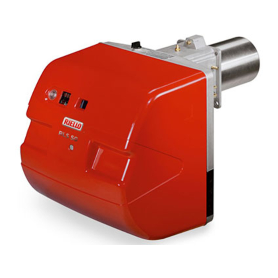
Page 15: Burner Description
Technical description of the burner 4.10 Burner description 23 20 10 20166791 D1118 20166770 Fig. 4 Combustion head 17 Gas input pipework Ignition electrodes 18 Boiler mounting flange Screw for combustion head adjustment 19 Flame stability disk Sleeve 20 Flame inspection window Minimum air pressure switch (differential operating type) 21 Control box with lock-out pilot light and lock-out reset button Air pressure test point... -
Page 16: Electrical Panel Description
Fig. 5 One switch for "burner on - off” one switch for “1st - 2nd stage" Fan motor contactor and thermal relay with reset button (RLS 50) Motor capacitor (RLS 28) Flame sensor LED panel Control box base 4-pole socket... -
Page 17: Control Box Rfgo-A22
Technical description of the burner 4.12 Control box RFGO-A22 Important notes To avoid accidents, material or environmental damage, observe the following instructions! The control box is a safety device! Avoid opening ATTENTION or modifying it, or forcing its operation. The Manufacturer cannot assume any responsibility for damage resulting from unauthorised work! ... -
Page 18: Servomotor (Lks 210
Technical description of the burner 4.13 Servomotor (LKS 210 ...) Important notes To avoid accidents, material or environmental damage, observe the following instructions! Avoid opening, modifying forcing ATTENTION actuators. All interventions (assembly and installation operations, assistance, etc.) must be carried out by qualified personnel. ... -
Page 19: Installation
Installation Installation Notes on safety for the installation After carefully cleaning all around the area where the burner is to The installation of the burner must be carried out be installed, and arranging for the environment to be illuminated by qualified personnel, as indicated in this manual correctly, proceed with the installation operations. -
Page 20: Operating Position
Provide an adequate lifting system. mal insulation screen supplied with the burner. Separate the combustion head from the rest of the burner RLS 28 (Fig. 11): RLS 38 disconnect the light oil pipes unscrewing the two unions 4). -
Page 21: Access To Head Internal Part
Installation Access to head internal part In order to reach inside the combustion head (Fig. 12) proceed as D1122 follows: remove the screw 1) and the internal part 2). Be careful as some drops of fuel may leak out dur- ing this phase. -
Page 22: Nozzle Installation
The burner complies with the emission requirements of the EN D1122 267 standard. In order to guarantee that emissions do not vary, recommended and/or alternative nozzles specified by Riello in the Instruction and warning booklet should be used. It is advisable to replace the nozzle once a year during periodical maintenance. -
Page 23: Combustion Head Adjustment
Installation Combustion head adjustment 5.9.1 Adjustments prior to ignition (with light oil) The adjustment of the combustion head depends only on the maximum output of the burner in the 2nd stage. Turn the screw 5)(Fig. 18) until the notch indicated by the diagram (Fig. -
Page 24: Light Oil Supply
Installation 5.10 Light oil supply Explosion danger due to fuel leaks in the pres- L [m] +/- H ence of a flammable source. Ø [mm] Precautions: avoid knocking, attrition, sparks and heat. Make sure the fuel shut-off valve is closed before performing any operation on the burner. -
Page 25: Hydraulic Connections
Installation 5.10.2 Hydraulic connections 5.10.3 Hydraulic circuit diagram Make sure that the hoses to the pump supply and return line are installed correctly. CAUTION The pumps are equipped with a by-pass that connects return line with suction line. They are installed on the burner with the by- pass closed by screw 6)(Fig. -
Page 26: Pump
Installation 5.11 Pump 5.11.1 Technical data Pump SUNTEC AL V65 B Min. delivery rate at 12 bar pressure 67 kg/h Delivery pressure range 4 - 18 bar Max. suction depression 0.45 bar Viscosity range 2 - 12 cSt. Max. light oil temperature 60°C Max. -
Page 27: Gas Supply
Installation 5.12 Gas supply Explosion danger due to fuel leaks in the pres- MBC “threaded” ence of a flammable source. Precautions: avoid knocking, attrition, sparks and heat. Make sure the fuel shut-off valve is closed before performing any operation on the burner. The fuel supply line must be installed by qualified personnel, in compliance with current standards and laws. -
Page 28: Gas Train
Installation 5.12.2 Gas train 5.12.4 Gas pressure Type-approved in accordance with EN 676 and supplied sepa- Tab. K indicates the pressure drops of the combustion head and rately from the burner. gas butterfly valve, on the basis of the burner operating output. To select the correct gas train model, refer to the manual "Burner- 1 p (mbar) gas train combination"... - Page 29 Installation Example RLS 28 with natural gas G20: 2nd stage operation Gas pressure at test point 1) (Fig. 29) 9.3 mbar Pressure in combustion chamber 2 mbar 9.3 - 2 7.3 mbar S9689 A pressure of 7.3 mbar, column 1, corresponds in Tab. K to an output of 210 kW.
-
Page 30: Electrical Connections
Fig. 30 ing. DANGER Key (Fig. 30) If the cover is still present, remove it and proceed with the electri- RLS 28 and RLS 38 cal wiring according to the wiring diagrams. Pg 11 Single-phase power supply Pg 11 Gas valves Use flexible cables in compliance with the EN 60 335-1 standard. -
Page 31: Calibration Of The Thermal Relay
Installation 5.14 Calibration of the thermal relay The thermal relay (Fig. 31) serves to avoid damage to the motor due to an excessive absorption increase or if a phase is missing. For calibration 2), refer to the table indicated in the electrical lay- out (electrical wiring in charge of the installer). -
Page 32: Start-Up, Calibration And Operation Of The Burner
Start-up, calibration and operation of the burner Start-up, calibration and operation of the burner Notes on safety for the first start-up The first start-up of the burner must be carried out Check the correct working of the adjustment, com- by qualified personnel, as indicated in this manual mand and safety devices. -
Page 33: Adjustments Prior To Ignition (Gas)
Start-up, calibration and operation of the burner Adjustments prior to ignition (gas) Combustion head adjustment is already described on page 21. Before starting up the burner, it is good practice to In addition, the following adjustments must also be made: adjust the gas train so that ignition takes place in ... -
Page 34: Burner Adjustment (Gas)
6.7.4 Operation with LPG - Propane - Butane dicated in page 11. The RLS 28 - 38 - 50 burners can operate also with LPG -Pro- Turn switch 2)(Fig. 33) to the 1st stage position: the servomotor pane-Butane. will close the air damper on the value previously set for the light oil and will control the opening of the 1st stage VR1 gas valve. -
Page 35: Servomotor Adjustment
Start-up, calibration and operation of the burner Servomotor adjustment The servomotor (Fig. 38) adjusts the air damper. Summarising, the lever must intervene according to the following sequence: Do not alter (for the moment) the factory setting for the 4 levers. A graduated label with 4 coloured sectors shows the intervention 1°... -
Page 36: Pressure Switch Adjustment
Start-up, calibration and operation of the burner Pressure switch adjustment 6.9.1 Air pressure switch - check CO Adjust the air pressure switch after performing all other burner adjustments with the air pressure switch set to the start of the scale (Fig. 39). With the burner operating in 1st stage, increase adjustment pres- sure by slowly turning the relevant knob clockwise until the burner locks out. -
Page 37: Operation Sequence Of The Burner
Start-up, calibration and operation of the burner 6.10 Operation sequence of the burner 6.10.1 Burner start-up Burner start-up 20141124 TL closes, fan motor starts, (in case of oil operation, pump motor starts) servomotor starts, maximum opening. 11 s air damper is at its maximum opening 42 s servomotor closing phase starts at the minimum output. -
Page 38: Final Checks (With Burner Operating)
Start-up, calibration and operation of the burner 6.11 Final checks (with burner operating) Open the thermostat/pressure switch TL The burner must stop Open the thermostat/pressure switch TS Turn the knob of the gas maximum pressure switch to the ... -
Page 39: Maintenance
Maintenance Maintenance Notes on safety for the maintenance The periodic maintenance is essential for the good operation, Before carrying out any maintenance, cleaning or checking oper- safety, yield and duration of the burner. ations: It allows you to reduce consumption and polluting emissions and to keep the product in a reliable state over time. - Page 40 Maintenance UV sensor LIGHT OIL OPERATION Clean the glass cover from any dust that may have accumulated. The photo-electric cell 1)(Fig. 45) is held in position by a pressure Pump fit and can therefore be removed by pulling it outward forcefully. The delivery pressure must comply with the table on page 24.
-
Page 41: Combustion Control (Gas)
Maintenance 7.2.5 Safety components GAS OPERATION The safety components should be replaced at the end of their life cycle indicated in the following table. Gas leaks Make sure that there are no gas leaks on the pipe between the The specified life cycles do not refer to the warranty terms indi- gas meter and the burner. -
Page 42: Opening The Burner
Maintenance Opening the burner Disconnect the electrical supply from the burner by means of the main system switch. D1141 DANGER Close the fuel shut-off valve. DANGER Wait for the components in contact with heat sources to cool down completely. Remove screw 1) and extract the cover 2). ... -
Page 43: Led Indicator And Special Function
LED indicator and special function LED indicator and special function Description of LED lamps It turns on when the fan motor is powered (T6) and blinks when RUN/CHECK switch is set to “CHECK” during damper movement phases, PTFI AND MTFI. S9740 It blinks when the air damper is moving towards the maximum opening position until the Damper... -
Page 44: Led Lamps: Burner Operating Status
LED indicator and special function LED lamps: burner operating status OPERATING STATUSES INDICATED BY LEDS DURING NORMAL OPERATION AND CHECK MODE Operation Damper Damper Modulation Ignition Flame Status LED ● = ON open closed Icon S9740 S9741 S9742 S9743 S9744 S9745 S9746 Power OFF/ON... -
Page 45: Problems - Causes - Remedies Signalled By Led Indicators
Problems - Causes - Remedies signalled by LED indicators Problems - Causes - Remedies signalled by LED indicators When an emergency stop occurs, the control device LEDs The regulation prohibits the system from allowing indicate the cause of the stop. more than 5 remote reset attempts within a 15 The terminal T3 is not powered. - Page 46 Problems - Causes - Remedies signalled by LED indicators Error / RFGO LED lock-out codes Faults LED 1 LED 2 LED 3 LED 4 LED 5 LED 6 LED 7 Operation Open Closed Auto Ignition Flame Status LED ● = ON damper damper Icon...
- Page 47 Problems - Causes - Remedies signalled by LED indicators Faults LED 1 LED 2 LED 3 LED 4 LED 5 LED 6 LED 7 Off-specification mains voltage ● ● ● ● ● UV: Internal fault ● ● Supervisor processor fault ●...
- Page 48 Problems - Causes - Remedies signalled by LED indicators Fault explanation Faults Cause Solution Post-diagnostics fault Initial power diagnostics fault Check T12, T13 and T14 Make sure that the status of inlets and outlets is correct upon ignition Local reset The user started the manual reset or the Check T21 inlet or reset for normal reset switch is faulty...
- Page 49 Problems - Causes - Remedies signalled by LED indicators Faults Cause Solution Internal processor timeout Internal fault Replace the control device Internal processor timeout Internal fault Replace the control device Combustion air check timeout The system could not perform verification Check the wiring or the air pressure switch tests of the combustion air during the burner sequence...
-
Page 50: Appendix - Accessories (Optional)
20097840 RLS 38 20097868 RLS 50 20097869 DEGASSING UNIT Burner Code RLS 28 - 38 - 50 (without filter) 3010054 RLS 28 - 38 - 50 (with filter) 3010055 CONNECTION FLANGE KIT Burner Code RLS 28 - 38 - 50... -
Page 51: B Appendix - Electrical Panel Layout
Appendix - Electrical panel layout Appendix - Electrical panel layout Index of layouts Indication of references Functional layout RFGO-A22 - RLS 28 Functional layout RFGO-A22 - RLS 38 Functional layout RFGO-A22 - RLS 50 Functional layout RFGO-A22 - RLS 28-38... - Page 52 Appendix - Electrical panel layout 20148646...
- Page 53 Appendix - Electrical panel layout 20148646...
- Page 54 Appendix - Electrical panel layout 20148646...
- Page 55 Appendix - Electrical panel layout 20148646...
- Page 56 Appendix - Electrical panel layout 20148646...
- Page 57 Appendix - Electrical panel layout 20148646...
- Page 58 Appendix - Electrical panel layout 20148646...
- Page 59 Appendix - Electrical panel layout 20148646...
- Page 60 Appendix - Electrical panel layout 20148646...
- Page 61 Appendix - Electrical panel layout 20148646...
- Page 62 Appendix - Electrical panel layout Wiring layout key Control box Pump motor capacitor Fan motor capacitor Protection fuses for three-phase line Fan motor thermal relay Remote lockout signalling Lockout signal for leak detection control 1st stage hour counter 2nd stage hour counter Fan motor contactor Relay Burner ON/OFF external switch...
- Page 64 RIELLO S.p.A. I-37045 Legnago (VR) Tel.: +39.0442.630111 http:// www.riello.it http:// www.riello.com Subject to modifications...