Table of Contents
Advertisement
Quick Links
Installation Instructions
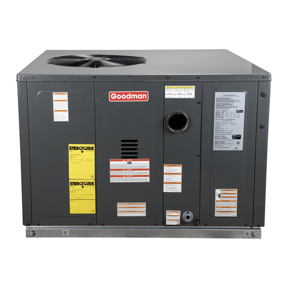
GPG 16 SEER "M" SERIES 2 - 4 Ton
Single Package Gas-Electric Heating & Cooling Units
ATTENTION INSTALLING PERSONNEL
Prior to installation, thoroughly familiarize yourself with this
Installation Manual. Observe all safety warnings. During in-
stallation or repair, caution is to be observed.
It is your responsibility to install the product safely and to
educate the customer on its safe use.
RECOGNIZE THIS SYMBOL AS A SAFETY PRECAUTION.
These installation instructions cover the outdoor installation
of self contained package air conditioners and heating units.
See the Specification Sheets applicable to your model for
information regarding accessories.
IOG-3012E
03/2021
"IMPORTANT - This product has been designed and manufactured to meet ENERGY STAR®
criteria for energy efficiency when matched with appropriate coil components. However,
proper refrigerant charge and proper air flow are critical to achieve rated capacity and
efficiency. Installation of this product should follow the manufacturer's refrigerant charging
and air flow instructions. Failure to confirm proper charge and air flow may reduce energy
efficiency and shorten equipment life."
Goodman Company, L.P.
19001 Kermier Rd., Waller, TX 77484
www.goodmanmfg.com
© 2015-2018, 2021 Goodman Company, L.P.
Affix this manual and Users Information Manual
adjacent to the unit.
O
NLY PERSONNEL THAT HAVE BEEN TRAINED TO INSTALL
(
SERVICE OR REPAIR
HEREINAFTER
SPECIFIED IN THIS MANUAL SHOULD SERVICE THE EQUIPMENT
MANUFACTURER WILL NOT BE RESPONSIBLE FOR ANY INJURY OR
PROPERTY DAMAGE ARISING FROM IMPROPER SERVICE OR SERVICE
. I
PROCEDURES
F YOU SERVICE THIS UNIT
RESPONSIBILITY FOR ANY INJURY OR PROPERTY DAMAGE WHICH MAY
. I
,
RESULT
N ADDITION
IN JURISDICTIONS THAT REQUIRE ONE OR
MORE LICENSES TO SERVICE THE EQUIPMENT SPECIFIED IN THIS
,
MANUAL
ONLY LICENSED PERSONNEL SHOULD SERVICE THE
. I
EQUIPMENT
MPROPER INSTALLATION
REPAIR OF THE EQUIPMENT SPECIFIED IN THIS MANUAL
,
ATTEMPTING TO INSTALL
ADJUST
EQUIPMENT SPECIFIED IN THIS MANUAL WITHOUT PROPER TRAINING
MAY RESULT IN PRODUCT DAMAGE
.
INJURY OR DEATH
*NOTE: Please contact your distributor or our website
for the applicable Specification Sheets referred to in this
manual.
This Forced Air Central Unit Design Complies With Re-
quirements Embodied In The American National Standard /
National Standard of Canada Shown Below.
ANSI Z21.47•CSA-2.3 Central Furnaces.
,
ADJUST
, "
")
SERVICE
THE EQUIPMENT
. T
HE
,
YOU ASSUME
,
,
ADJUSTMENT
SERVICING OR
,
OR
,
SERVICE OR REPAIR THE
,
,
PROPERTY DAMAGE
PERSONAL
,
Advertisement
Table of Contents

Related Manuals for Goodman GPG 16 M Series


Summary of Contents for Goodman GPG 16 M Series
- Page 1 Installation of this product should follow the manufacturer’s refrigerant charging and air flow instructions. Failure to confirm proper charge and air flow may reduce energy efficiency and shorten equipment life.” Goodman Company, L.P. 19001 Kermier Rd., Waller, TX 77484 IOG-3012E www.goodmanmfg.com 03/2021 © 2015-2018, 2021 Goodman Company, L.P.
-
Page 2: Table Of Contents
When reporting shortages or damages, or ordering repair parts, give the complete unit model and serial numbers as HOMEOWNER SUPPORT stamped on the unit’s nameplate. GOODMAN MANUFACTURING COMPANY, L.P. 19001 KERMIER ROAD WALLER, TEXAS 77484 (877) 254-4729... -
Page 3: Safety Instructions
SAFETY INSTRUCTIONS To The Installer Before installing this unit, please read this manual to famil- iarize yourself on the specific items which must be adhered to, including maximum external static pressure to unit, air temperature rise, minimum or maximum CFM and motor speed connections. - Page 4 CARBON MONOXIDE POISONING HAZARD RISQUE D’INTOXICATION AU MONOXYDE DE CARBONE Failure To Follow The Steps Outlined Below For Each Appliance Si les étapes décrites ci-dessous ne sont pas suivies pour chacun Connected To The Venting System Being Placed Into Operation des appareils raccordés au système de ventilation au moment Could Result In Carbon Monoxide Poisoning Or Death.
-
Page 5: General Information
In the event of damage, the mercial models. Specification sheets can be found at www. receiver should: goodmanmfg.com for Goodman® brand products. With- 1. Make notation on delivery receipt of any visible dam- in the website, please select the residential or commercial age to shipment or container. -
Page 6: Unit Location
UNIT LOCATION IMPORTANT NOTE: Remove wood shipping rails prior to installation of the unit. All Installations: • For proper flame pattern within the heat exchanger and proper condensate drainage, the unit must be mounted level. • The flue outlet hood must be at least 12 inches from any opening through which flue gases could enter a building, and at least three feet above any forced air inlet located within ten feet. -
Page 7: Roof Curb Installations Only
Roof Curb Installations Only: • Sufficient structural support must be determined prior to locating and mounting the curb and package unit. • Ductwork must be constructed using industry guide- lines. The duct work must be placed into the roof curb before mounting the package unit. -
Page 8: Piping
D’installation de ce générateur de chaleur à des altitudes • Listed gas appliance connectors used in accordance supérieures à 2000 pi (610 m) doit être effectuée conformé- with the terms of their listing that are completely in the ment auxinstructions accompagnant la trousse de conver- same room as the equipment sion pour haute altitude fournie avec cet appareil. -
Page 9: Propane Gas Installations
PROPANE GAS INSTALLATIONS CAUTION To prevent property damage or personal injury due to fire, the following instructions must be performed regarding gas connections and pressure testing • The unit and its gas connections must be leak tested be- fore placing in operation. Because of the danger of ex- plosion or fire, never use a match or open flame to test for leaks. -
Page 10: Electrical Wiring
Single Stage Thermostat Sizing Between Single or Second Stage Regulator and Appliance* Maximum Propane Capacities Listed are Based on 1/2" W.C. Pressure Drop at 11" W.C. Setting. Capacities in 1,000 BTU/HR PIPE OR NOMINAL PIPE SIZE, TUBING TUBING SIZE, O.D., TYPE L SCHEDULE 40 LENGTH, FEET... -
Page 11: Circulating Air And Filters
Ductwork Duct systems and register sizes must be properly designed for the C.F.M. and external static pressure rating of the unit. Ductwork should be designed in accordance with the recom- mended methods of Air Conditioning Contractors of Ameri- For unit protection, use a fuse or hacr circuit breaker that is ca Manual D (Residential) or Manual Q (Commercial). -
Page 12: Installation - Flue Hood Exhaust
4. Using the three screws provided, attach the hood (with 1. Thermostat calls for low or high stage heating. the opening facing down) over the flue exhaust open- 2. Induced draft blower energizes for 15-second pre- ing in the utility panel. purge. -
Page 13: Fan Only
Fan Only Secondary Limit Control 1. Thermostat calls for FAN ONLY by energizing “G”. The secondary limit control is located on the top of the blower 2. The indoor blower is immediately energized at the low scroll assembly. This control opens when elevated tempera- heat speed. - Page 14 Open to Atmosphere High Fire Regulator Outlet Adjust Regulator Pressure Boss Vent Low Fire Regulator Adjust Inlet Pressure Boss High Fire Coaxial Coil Coil Terminal (HI) Terminal (M) On/Off Switch Common Terminal (C) White-Rodgers Model 36G54 connected to Manometer Gas Inlet Pressure Check ....
-
Page 15: Gas Btu Input Check
Manifold Gas Pressure Range Nominal Low Sta ge 1.7 - 2.3" w.c. 2.0" w.c. Na tura l Hi gh Sta ge 3.2 - 3.8" w.c. 3.5" w.c. Low Sta ge 5.7 - 6.3" w.c. 6.0" w.c. Propa ne Hi gh Sta ge 9.7 - 10.3"... -
Page 16: Cooling Startup
4. Consult proper table for quantity of air. If the external static pressure exceeds the minimum or max- imum allowable statics, check for closed dampers, dirty fil- ters, undersized or poorly laid out ductwork. Blower Speed Adjustments Blower speeds are changed at the indoor blower. The igni- tion control board has four blower speeds: LOW HEAT, HI HEAT, LOW COOL and HIGH COOL. -
Page 17: Superheat
expansion valve, charge the system to sub-cooling, range sponding to its pressure. The degree of subcooling equals shown on chart, when necessary, adjust expansion valve the degrees of temperature decrease below the saturation stem for superheat setting. temperature at the existing pressure. 1. -
Page 18: Abnormal Operation - Heating
Abnormal Operation - Heating burner bracket. The cause of the flame rollout must be determined and corrected before resetting the limit. Internal Control Failure • Check wiring Check wiring for opens/shorts and miswiring. If the integrated ignition control in this unit encounters an internal fault, it will go into a “hard”... -
Page 19: Low Flame Signal
Low Flame Signal Filter Replacement or Cleaning Under some conditions, the fuel or air supply can create a A return air filter is not supplied with this unit; however, there nearly invisible coating on the flame sensor. This coating must be a means of filtering all of the return air. The filter(s) acts as an insulator causing a drop in the flame signal. -
Page 20: Flue Passages (Qualified Servicer Only)
Flue Passages (Qualified Servicer Only) At the start of each heating season, inspect and, if neces- sary, clean the unit flue passage. Cleaning Flue Passages (Qualified Servicer Only) Check the Burner Flames for: 1. Shut off electric power and gas supply to the unit. 1. -
Page 21: Accessories And Functional Parts
ACCESSORIES AND FUNCTIONAL PARTS Functional Parts FUNCTIONAL PARTS Sheet Metal Accessories Additional accessories can be purchased to fit specific appli- Auxi l i a ry Li mi t Swi tch Fl a me Sens or cation needs. Parts and instructions are available from your Bl ower Hous i ng Ga s Ori fi ce distributor. -
Page 22: Appendix
APPENDIX Ignition Control Diagnostic Indicator Chart Red Light Signal Refer to Abnormal Heating or Cooling Operation Sections of this Manual Internal Control Failure 1 Flash External Lockout 2 Flashes Pressure Switch Stuck Open 3 Flashes Pressure Switch Stuck Closed 4 Flashes Thermal Protection Device Open 5 Flashes Flame Detected with Gas Valve Closed... -
Page 23: Unit Dimensions
UNIT DIMENSIONS Unit Dimensions (Inches) Chassis Model Size Height GPG1624***M41** 34 1/2 Medium GPG1630***M41** 34 1/2 Medium POWER WIRE ENTRANCE GPG1636***M41** 42 1/2 Large 1.375 4.125 GPG1642***M41** 42 1/2 Large 2.125 42 1/2 Large GPG1648***M41** GPG1660***M41B* 73 3/8 47 5/8 43 1/2 X-Large RETURN... -
Page 24: Wiring Diagram
GPG16*****M41A** WIRING DIAGRAM HIGH VOLTAGE! ISCONNECT POWER BEFORE SERVICING ULTIPLE POWER SOURCES MAY BE PRESENT AILURE TO DO SO MAY CAUSE PROPERTY DAMAGE, PERSONAL INJURY OR DEATH PLY VOLTAGE 208- 230/1/6 COMP SEE NOTE 4 SEE NOTE 3 SEE NOTE 2 POWER SUPPLY 208-230/1/160 SEE NOTE 3... -
Page 25: Minimum Clearances
MINIMUM CLEARANCES Clearance in accordance with local installation codes, the requirements of the gas supplier and the manufacturer’s instal- lation instructions. Dégaugement conforme aux codes d’installation locaux, aux exigences du fournisseur de gaz et aux instructions d’instal- lation du fabricant. 48"... -
Page 26: Blower Performance
BLOWER PERFORMANCE DATA GPG1624060M41** - Rise Range: 35° - 65° T1 LOW STAGE HEATING T2 HIGH STAGE HEATING T3 LOW STAGE T4 HIGH STAGE T5 COOLING SPEED E.S.P. SPEED SPEED COOLING SPEED COOLING SPEED WATTS RISE WATTS RISE WATTS WATTS WATTS 1,090 1,055... - Page 27 PACKAGE UNITS - DUAL FUEL & GAS HOMEOWNER’S ROUTINE MAINTENANCE RECOMMENDATIONS We strongly recommend a bi-annual maintenance checkup be performed by a qualified service agency before the heating and cooling seasons begin. Replace or Clean Filter TP-109 (shipped in the literature bag with the unit) to clean the coils.
-
Page 28: Start-Up Checklist
Start-up Checklist *Store in job file Air Conditioning & Heating Date: ___________________________________ Loca�on: __________________________________________ Model Number: ___________________________________ __________________________________________ Serial Number: ___________________________________ __________________________________________ Technician: ___________________________________ Unit #: __________________________________________ Pre Start-Up (Check each item as completed) Verify all packaging material has been removed. Remove all shipping brackets per installa�on instruc�ons. - Page 29 Start-up Checklist Air Conditioning & Heating Start-Up (Insert the values as each item is completed.) ELECTRICAL Supply Voltage L1 - L2 L2 - L3 L3 - L1 Circuit 1 Compressor Amps Circuit 2 Compressor Amps Blower Amps Condenser Fan Amps Fan 1 Fan 2 Fan 3...
- Page 30 THIS PAGE LEFT INTENTIONALLY BLANK...
- Page 31 THIS PAGE LEFT INTENTIONALLY BLANK...
- Page 32 We use quality materials and components. Finally, every unit is run tested before it leaves the factory. That’s why we know. . .There’s No Better Quality. Goodman Company, L.P. 19001 Kermier Rd., Waller, TX 77484 www.goodmanmfg.com © 2015-2018, 2021 Goodman Company, L.P.