Advertisement
Available languages
Available languages
Quick Links
G e n e r a l i n f o r ma t i o n :
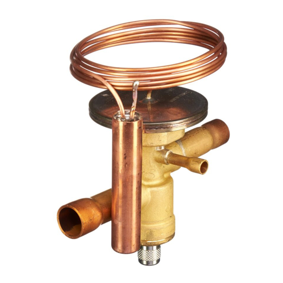
EMERSON's TX7 Thermo™-Expansion Valves are
designed for air conditioning, chillers, rooftops, close
control, A/C transportation, heat pumps and industrial
cooling process applications.
S a f e t y i n s t r u c t i o n s :
• Read operating instructions thoroughly. Failure
to comply can result in device failure, system
damage or personal injury.
• According to EN 13313 it is intended for use by
persons having the appropriate knowledge and
skill.
• Before opening any system make sure pressure
in system is brought to and remains at
atmospheric pressure.
• Do not release any refrigerant into the
atmosphere!
• Do not exceed the specified maximum ratings for
pressure and temperature.
• Do not use any other fluid media without prior
approval of EMERSON. Use of fluids not listed
could result in: Change of hazard category of
product and consequently change of conformity
assessment
requirement
accordance with European pressure equipment
directive 97/23/EC.
• Ensure that design, installation and operation
are according
to
European and
standards/regulations.
M o u n t i n g l o c a t i o n :
• Valves may be installed in any position, but should
be located as close as possible to the distributor or
evaporator inlet.
• Uni- and bi-flow operation possible. Following
recommendations need to be considered: (Fig. 8)
Uni-flow application: A as inlet / B as outlet
Bi-flow application: (Fig. 2)
"A" connection as inlet during cooling mode (Flow
circulation I), "B" connection as inlet during heating
mode (Flow circulation II).
B r a z i n g : ( F i g . : 1 )
• Perform and consider the brazing joint as per
EN 14324.
• Before and after brazing clean tubing and brazing
joints.
• Do not exceed the max. body temperature of
120 C!
I n s t a l l a t i o n :
W a r n i n g :
• Do not bend capillary tube at interface to head of
valve. Allowed: distance D (10 mm) and radius
R (5 mm).
Fig.: 3
Emerson Climate Technologies GmbH
Am Borsigturm 31 I 13507 Berlin I Germany
Thermo™-Expansion Valve TX7
• Securely fasten the bulb with straps provided.
Insulate bulb with a suitable material. The location
of bulb on suction line is dependent to size of
suction line (see Fig. 4)
• Be sure that the external equalizer line cannot
siphon oil from the suction line.
• The expansion valve must be protected against all
contaminants. Install a filter drier before the valve.
• Install a sight glass before the valve.
P r e s s u r e T e s t :
After completion of installation, a pressure test must
be carried out as follows:
- according to EN 378 for systems which must
comply with European pressure equipment
directive 97/23/EC.
- to maximum working pressure of system for other
applications.
W a r n i n g :
• Failure to do so could result in loss of refrigerant
and personal injury.
• The pressure test must be conducted by skilled
persons with due respect regarding the danger
related to pressure.
for
product
in
O p e r a t i o n :
Check for leaks, sufficient refrigerant charge and be
sure no flash gas is present before attempting to check
valve operation.
national
P r o p e r o p e r a t i o n o f c h a r g e s :
• The maximum bulb temperature is limited to:
Z1, M1 and N1 (MOP charge): +120°C
M0 (liquid charge):+90°C
N0 (liquid charge): +80°C
W a r n i n g :
Valves with gas charge feature MOP function and
operate properly only if the temperature at the
bulb is below the temperature at the head of the
valve and at the capillary tube (see Fig. 5). If valve
head becomes colder than the bulb, malfunction of
the expansion valve occurs (i.e. erratic low pressure
or excessive superheat).
S u p e r h e a t A d j u s t m e n t
If the superheat must be adjusted for the application
proceeds as follows:
1. Remove seal cap from bottom of valve.
2. Turn the adjustment screw clockwise to increase the
superheat
superheat.
Changes in Superheat (K) per stem turn depending
on evaporating temperature and refrigerant:
Refrigerant/
Type
R410A (Z)
R134a (M)
R407C (N)
R450A
R513A
R32
R22
As much as 15 minutes are required for the system
to stabilize after the adjustment is made.
3. Determine superheat "sh" according to Fig. 6.
4. Replace and tighten seal cap (hand tight).
www.emersonclimate.eu
Operating instruction
and
counterclockwise
to
decrease
Evaporating temperature [°C]
0
5
-10
0.3
0.3
0.4
0.7
0.8
1.0
0.4
0.5
0.7
0.8
0.9
1.2
0.6
0.7
1.0
0.3
0.3
0.4
0.4
0.5
0.6
Date: 20.05.2016
F a c t o r y s e t t i n g s :
The table below provides the factory setting position
of superheat adjusting stem.
Charge
Number of turns clockwise when adjusting
Code
stem fully open counterclockwise
Z1
M0
M1
N0
N1
TX7
in
systems
refrigerants:
The following refrigerants can be used with standard
available charges when factory setting to be
readjusted. The readjustment depends to operating
evaporating temperature and it is as guideline as
follows:
Charge
Refrigerant/
code
Type
Z1
R32
M0/M1
R450A
R513A
M0/M1 -3
N0/N1
R22
❶
4.4K static superheat
❷
4.8K static superheat
W a r n i n g :
There are max. 11.5 turns on the adjustment stem
(from left stop to right stop). When stop is reached
any further turning will damage the valve.
Fig.: 7
Note:
+ = Clockwise rotation
- = Counterclockwise rotation
S e r v i c e / M a i n t e n a n c e :
Defective TX7 must be replaced, they cannot be
repaired.
T e c h n i c a l D a t a :
Max. working pressure PS:
Factory test pressure PT:
-20
Medium temperature range TS:
0.5
Group fluid:
1.4
Medium compatibility:
0.9
Dimensions:
1.7
Marking:
1.3
0.5
0.9
TX7_OI_ML_R01_866200.docx
+2 (2x360°)
+4 (4x360°)
+6 (6x360°)
+8 (8x360°)
+11 (11x360°)
with
nonstandard
Evaporating temperature [°C]
0
+5
-10
-20
Number of turn
---
-1
---
+2
+4
+4.5
+3
+2.5
❶
❷
-3
-3
-2
-4
-4
-3
-3.5
46 bar
50.6 bar
-20...+70°C
II
HFC, HCFC,
HFO blends
Fig. 8
EAC (pending)
UL (pending)
Advertisement

Related Manuals for Emerson Alco Controls Thermo-TX7


Summary of Contents for Emerson Alco Controls Thermo-TX7
- Page 1 Number of turn • Do not use any other fluid media without prior • The pressure test must be conducted by skilled approval of EMERSON. Use of fluids not listed persons with due respect regarding the danger M0/M1 R450A +4.5...
- Page 2 A c h t u n g : Verdampfungstemperatur Temperatur nicht überschreiten. [°C] • Bei Nichtbeachten droht Kältemittelverlust und Füllungs- • Es dürfen nur von EMERSON freigegebene Verletzungsgefahr. Kältemittel kennzahl Medien eingesetzt werden. Die Verwendung • Die Druckprüfung darf nur von geschulten und...
- Page 3 R é g l a g e s d ' u s i n e : fournis et isoler l’ensemble avec une matière Les détendeurs EMERSON de la série TX7 sont Le tableau ci-dessous indique le réglage usine de la adéquate.
- Page 4 I n f o r ma c i ó n g e n e r a l : utilizando las abrazaderas que se incluyen con la 4. Vuelva a colocar y apretar la caperuza. (apretándola Las válvulas de expansión TX7 de EMERSON están válvula. Aísle el bulbo con un material adecuado. a mano) diseñadas para su instalación en sistemas de aire...
- Page 5 I n f o r ma z i o n i g e n e r a l i : il bulbo con materiale isolante adeguato La 15 min. perché il sistema si stabilizzi. Le valvole di espansione termostatica EMERSON posizione del bulbo sulla tubazione di aspirazione 3. Regolare il surriscaldamento (Fig. 6).
- Page 6 О б щ а я и н ф о р м а ц и я : • Надежно закрепите термобаллон прилагаемыми 4. Установите заглушку на место (закрутите Термо-расширительные клапаны EMERSON серии крепежными скобами и заизолируйте вручную). TX7 сконструированы для работы в системах...
- Page 7 TX7-..6 7/8” 1-1/8” 1/4" TX7-..6M TX7-..7 7/8” 1-1/8” 1/4" TX7-..7M 95.2 40.5 15.9 18.9 TX7-..8 7/8” 1-1/8” 1/4" TX7-..8M TX7-..9 7/8” 1-1/8” 1/4" TX7-..9M Emerson Climate Technologies GmbH www.emersonclimate.eu Am Borsigturm 31 I 13507 Berlin I Germany Date: 20.05.2016 TX7_OI_ML_R01_866200.docx...