Table of Contents
Advertisement
Available languages
Available languages
Quick Start
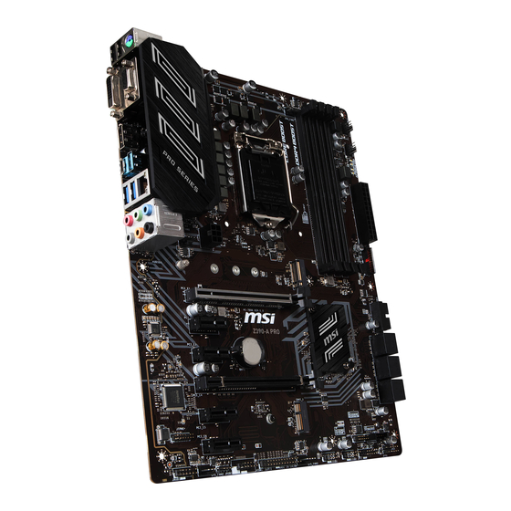
Thank you for purchasing the MSI
Z390-A PRO
motherboard. This
®
Quick Start section provides demonstration diagrams about how to
install your computer. Some of the installations also provide video
demonstrations. Please link to the URL to watch it with the web
browser on your phone or tablet. You may have even link to the URL
by scanning the QR code.
Kurzanleitung
Danke, dass Sie das MSI
Z390-A PRO
Motherboard gewählt
®
haben. Dieser Abschnitt der Kurzanleitung bietet eine Demo zur
Installation Ihres Computers. Manche Installationen bieten auch
die Videodemonstrationen. Klicken Sie auf die URL, um diese
Videoanleitung mit Ihrem Browser auf Ihrem Handy oder Table
anzusehen. Oder scannen Sie auch den QR Code mit Ihrem Handy,
um die URL zu öffnen.
Présentation rapide
Merci d'avoir choisi la carte mère MSI
Z390-A
PRO. Ce manuel
®
fournit une rapide présentation avec des illustrations explicatives
qui vous aideront à assembler votre ordinateur. Des tutoriels vidéo
sont disponibles pour certaines étapes. Cliquez sur le lien fourni
pour regarder la vidéo sur votre téléphone ou votre tablette. Vous
pouvez également accéder au lien en scannant le QR code qui lui est
associé.
Быстрый старт
Благодарим вас за покупку материнской платы MSI
Z390-A
PRO.
®
В этом разделе представлена информация, которая поможет вам
при сборке комьютера. Для некоторых этапов сборки имеются
видеоинструкции. Для просмотра видео, необходимо открыть
соответствующую ссылку в веб-браузере на вашем телефоне или
планшете. Вы также можете выполнить переход по ссылке, путем
сканирования QR-кода.
I
Quick Start
Advertisement
Chapters
Table of Contents

Related Manuals for MSI Z390-A PRO


Summary of Contents for MSI Z390-A PRO
- Page 1 Videoanleitung mit Ihrem Browser auf Ihrem Handy oder Table anzusehen. Oder scannen Sie auch den QR Code mit Ihrem Handy, um die URL zu öffnen. Présentation rapide Merci d’avoir choisi la carte mère MSI Z390-A PRO. Ce manuel ® fournit une rapide présentation avec des illustrations explicatives qui vous aideront à...
- Page 2 Installing a Processor/ Installation des Prozessors/ Installer un processeur/ Установка процессора Youtube http://youtu.be/bf5La099urI Quick Start...
- Page 3 Installing DDR4 memory/ Installation des DDR4-Speichers/ Installer une mémoire DDR4/ Установка памяти DDR4 Youtube http://youtu.be/T03aDrJPyQs DIMMB2 DIMMB2 DIMMB1 DIMMA2 DIMMA2 DIMMA2 DIMMA1 Quick Start...
- Page 4 Connecting the Front Panel Header/ Anschließen der Frontpanel-Stiftleiste/ Connecter un connecteur du panneau avant/ Подключение разъемов передней панели Youtube http://youtu.be/DPELIdVNZUI Power LED Power Switch JFP1 Reserved HDD LED Reset Switch HDD LED + Power LED + HDD LED - Power LED - Reset Switch Power Switch Reset Switch...
- Page 5 Installing the Motherboard/ Installation des Motherboards/ Installer la carte mère/ Установка материнской платы Quick Start...
- Page 6 Installing SATA Drives/ Installation der SATA-Laufwerke/ Installer le disque dur SATA/ Установка дисков SATA Youtube http://youtu.be/RZsMpqxythc Quick Start...
- Page 7 Installing a Graphics Card/ Einbau der Grafikkarte/ Installer une carte graphique/ Установка дискретной видеокарты Youtube http://youtu.be/mG0GZpr9w_A Quick Start...
- Page 8 Connecting Peripheral Devices/ Peripheriegeräte/ Connecter un périphérique anschliessen/ Подключение периферийных устройств VIII Quick Start...
- Page 9 Connecting the Power Connectors/ Stromanschlüsse anschliessen/ Connecter les câbles du module d’alimentation/ Подключение разъемов питания Youtube http://youtu.be/gkDYyR_83I4 ATX_PWR1 CPU_PWR1 PCIE_PWR1 Quick Start...
- Page 10 Power On/ Einschalten/ Mettre sous-tension/ Включение питания Quick Start...
-
Page 11: Table Of Contents
Contents Safety Information ....................2 Specifications ......................3 Package contents ....................8 Rear I/O Panel ....................... 9 Overview of Components ..................12 CPU Socket ......................13 DIMM Slots ......................14 PCI_E1~6: PCIe Expansion Slots ................15 SATA1~6: SATA 6Gb/s Connectors ............... 15 M2_1: M.2 Slot (Key M) .................. -
Page 12: Safety Information
Safety Information ∙ The components included in this package are prone to damage from electrostatic discharge (ESD). Please adhere to the following instructions to ensure successful computer assembly. ∙ Ensure that all components are securely connected. Loose connections may cause the computer to not recognize a component or fail to start. -
Page 13: Specifications
* The SATA2 will be unavailable when installing M.2 SATA device into M.2 slot. ** Before using Intel Optane™ memory modules, please ensure that you have ® updated the drivers and BIOS to the latest version from MSI website. Continued on next page Specifications... - Page 14 Continued from previous page Intel Z390 Chipset ® RAID ∙ Supports RAID 0, RAID1, RAID 5 and RAID 10 for SATA storage devices ∙ 1x Intel I219-V Gigabit LAN controller ® ∙ Intel Z390 Chipset ® ▪ 2x USB 3.1 Gen2 (SuperSpeed USB 10Gbps) ports (1x Type-A port and 1x Type-C port) on the back panel ▪...
- Page 15 Continued from previous page ∙ 1x 24-pin ATX main power connector ∙ 1x 8-pin ATX 12V power connector ∙ 1x 6-pin ATX 12V power connector ∙ 6x SATA 6Gb/s connectors ∙ 2x M.2 slots (1 M-Key slot,1 E-Key slot) ∙ 2x USB 3.1 Gen1 connectors (supports additional 4 USB 3.1 Gen1 ports) ∙...
- Page 16 ∙ ACPI 6.1, SMBIOS 2.8 ∙ Multi-language ∙ Drivers ∙ DRAGON CENTER ∙ MYSTIC LIGHT Software ∙ CPU-Z MSI GAMING ∙ Intel Extreme Tuning Utility ® ∙ Google Chrome™ ,Google Toolbar, Google Drive ∙ Norton™ Internet Security Solution ∙ OC Performance ∙...
- Page 17 Continued from previous page ∙ Protection ▪ PCI-E Steel Armor ▪ PCI-E Steel Slot ∙ Performance ▪ Core Boost ▪ OC Genie ▪ Multi GPU-CrossFire Technology Special Features ▪ DDR4 Boost ▪ USB with type A+C ▪ Intel Turbo USB 3.1 Gen2 ∙...
-
Page 18: Package Contents
Package contents Please check the contents of your motherboard package. It should contain: Motherboard Z390-A PRO Cable SATA 6Gb/s Cables M.2 Screw I/O Shield Accessories Case Badge VIP Card Application DVD Driver DVD Documentation Quick Installation Guide ⚠ Important If any of the above items are damaged or missing, please contact your retailer. -
Page 19: Rear I/O Panel
Rear I/O Panel Audio Ports PS/2 USB 3.1 Gen2 Type-A DisplayPort USB 2.0 DVI-D USB 3.1 Gen1 Type-A USB 3.1 Gen2 Type-C LAN Port LED Status Table Link/ Activity LED Speed LED Status Description Status Description No link 10 Mbps connection Yellow Linked Green... - Page 20 Realtek Audio Console After Realtek Audio Console is installed. You can use it to change sound settings to get better sound experience. Application Enhancement Advanced Settings Device Selection Main Volume Connector Settings Jack Status ∙ Device Selection - allows you to select a audio output source to change the related options.
- Page 21 Audio jacks to headphone and microphone diagram Audio jacks to stereo speakers diagram AUDIO INPUT Audio jacks to 7.1-channel speakers diagram AUDIO INPUT Front Center/ Subwoofer Side Rear Rear I/O Panel...
-
Page 22: Overview Of Components
Overview of Components CPU Socket DIMMA1 DIMMA2 PCIE_PWR1 DIMMB1 CPU_FAN1 DIMMB2 CPU_PWR1 PUMP_FAN1 SYS_FAN5 SYS_FAN4 ATX_PWR1 SYS_FAN1 JUSB4 M2_1 PCI_E1 JUSB3 PCI_E2 SATA▼1▲2 PCI_E3 JBAT1 SATA▼3▲4 PCI_E4 SATA▼5▲6 PCI_E5 CNVI_1 JTPM1 PCI_E6 JTBT1 JOC1 JAUD1 JFP2 SYS_FAN2 JFP1 JRGB1 JUSB2 JCOM1 JUSB1 JLPT1... -
Page 23: Cpu Socket
Always unplug the power cord from the power outlet before installing or removing the CPU. Please retain the CPU protective cap after installing the processor. MSI will deal ∙ with Return Merchandise Authorization (RMA) requests if only the motherboard comes with the protective cap on the CPU socket. -
Page 24: Dimm Slots
DIMM Slots DIMMA1 DIMMB1 Channel A Channel B DIMMA2 DIMMB2 Memory module installation recommendation DIMMB2 DIMMB2 DIMMB1 ⚠ DIMMA2 DIMMA2 DIMMA2 DIMMA1 Important Always insert memory modules in the DIMMA2 slot first. ∙ Due to chipset resource usage, the available capacity of memory will be a little less ∙... -
Page 25: Pci_E1~6: Pcie Expansion Slots
If you install a large and heavy graphics card, you need to use a tool such as ∙ MSI Gaming Series Graphics Card Bolster to support its weight and to prevent deformation of the slot. For a single PCIe x16 expansion card installation with optimum performance, using ∙... -
Page 26: M2_1: M.2 Slot (Key M)
M2_1: M.2 Slot (Key M) ⚠ Important Intel RST only supports PCIe M.2 SSD with UEFI ROM. ∙ ® Intel Optane™ Memory Ready. ∙ ® ⚽ Video Demonstration Watch the video to learn how to Install M.2 module. http://youtu.be/JCTFABytrYA Installing M.2 device 1. -
Page 27: Jfp1, Jfp2: Front Panel Connectors
JFP1, JFP2: Front Panel Connectors These connectors connect to the switches and LEDs on the front panel. Power LED Power Switch JFP1 Reserved HDD LED Reset Switch HDD LED + Power LED + HDD LED - Power LED - Reset Switch Power Switch Reset Switch Power Switch... -
Page 28: Cpu_Pwr1, Atx_Pwr1, Pcie_Pwr1: Power Connectors
CPU_PWR1, ATX_PWR1, PCIE_PWR1: Power Connectors These connectors allow you to connect an ATX power supply. CPU_PWR1 Ground +12V Ground +12V Ground +12V Ground +12V +3.3V +3.3V +3.3V -12V Ground Ground PS-ON# Ground Ground Ground ATX_PWR1 Ground Ground PWR OK 5VSB +12V +12V +3.3V... -
Page 29: Jusb3~4: Usb 3.1 Gen1 Connectors
However, when you boot the computer into Windows ® you will need to install the MSI Dragon Center application to turn ON/OFF the Charging mode. ⚠... -
Page 30: Jusb1~2: Usb 2.0 Connectors
In order to recharge your iPad,iPhone and iPod through USB ports, please install ∙ MSI Dragon Center utility. ∙ The CNVI_1 and JUSB2 share the same bandwidth. And one USB port connecting to JUSB2 is unavailable when the CNVI_1 slot has been installed. -
Page 31: Cpu_Fan1, Pump_Fan1, Sys_Fan1~5: Fan Connectors
CPU_FAN1, PUMP_FAN1, SYS_FAN1~5: Fan Connectors Fan connectors can be classified as PWM (Pulse Width Modulation) Mode or DC Mode. PWM Mode fan connectors provide constant 12V output and adjust fan speed with speed control signal. DC Mode fan connectors control fan speed by changing voltage. This motherboard can automatically detect PWM and DC mode. -
Page 32: Jaud1: Front Audio Connector
JAUD1: Front Audio Connector This connector allows you to connect audio jacks on the front panel. MIC L Ground MIC R Head Phone R MIC Detection SENSE_SEND No Pin Head Phone L Head Phone Detection JCI1: Chassis Intrusion Connector This connector allows you to connect the chassis intrusion switch cable. Normal Trigger the chassis intrusion event... -
Page 33: Jbat1: Clear Cmos (Reset Bios) Jumper
JBAT1: Clear CMOS (Reset BIOS) Jumper There is CMOS memory onboard that is external powered from a battery located on the motherboard to save system configuration data. If you want to clear the system configuration, set the jumpers to clear the CMOS memory. Keep Data Clear CMOS/ Reset BIOS... -
Page 34: Jrgb1: Rgb Led Connector
∙ before installing or removing the LED strip. ∙ Please use MSI’s software to control the extended LED strip. EZ Debug LED These LEDs indicate the debug status of the motherboard. CPU - indicates CPU is not detected or fail. -
Page 35: Installing Os, Drivers & Utilities
Installing OS, Drivers & Utilities Please download and update the latest utilities and drivers at www.msi.com Installing Windows ® 1. Power on the computer. 2. Insert the Windows 10 installation disc/USB into your computer. ® 3. Press the Restart button on the computer case. -
Page 36: Bios Setup
∙ Press Delete key, when the Press DEL key to enter Setup Menu, F11 to enter Boot Menu message appears on the screen during the boot process. ∙ In MSI Dragon Center application, click on GO2BIOS button and choose OK. The system will reboot and enter BIOS setup directly. -
Page 37: Resetting Bios
Updating BIOS Updating BIOS with M-FLASH Before updating: Please download the latest BIOS file that matches your motherboard model from MSI website. And then save the BIOS file into the USB flash drive. Updating BIOS: 1. Insert the USB flash drive that contains the update file into the USB port. -
Page 38: Ez Mode
EZ Mode At EZ mode, it provides the basic system information and allows you to configure the basic setting. To configure the advanced BIOS settings, please enter the Advanced Mode by pressing the Setup Mode switch or F7 function key. XMP switch Setup Mode switch Screenshot... - Page 39 ∙ Information display - click on the CPU, Memory, Storage, Fan Info and Help buttons on left side to display related information. ∙ Function buttons - enable or disable the LAN Option ROM, M.2/ Optane Genie, HD audio controller, AHCI/ RAID, CPU Fan Fail Warning Control and BIOS Log Review by clicking on their respective button.
-
Page 40: Advanced Mode
Advanced Mode Press Setup Mode switch or F7 function key can switch between EZ Mode and Advanced Mode in BIOS setup. XMP switch Setup Mode switch Screenshot Search Language System information OC GENIE 4 switch Boot device priority bar BIOS menu BIOS menu selection selection... -
Page 41: Oc Menu
OC Menu This menu is for advanced users who want to overclock the motherboard. ⚠ Important Overclocking your PC manually is only recommended for advanced users. ∙ Overclocking is not guaranteed, and if done improperly, it could void your warranty ∙... - Page 42 ▶ GT Ratio [Auto] Sets the integrated graphics ratio. The valid value range depends on the installed CPU. ▶ Adjusted GT Frequency Shows the adjusted integrated graphics frequency. Read-only. ▶ Misc Setting* Press Enter, + or - key to open or close the following 3 items related to CPU features. ▶...
- Page 43 ▶ Memory Try It ! [Disabled] It improve memory compatibility or performance by choosing optimized memory preset. ▶ Advanced DRAM Configuration Press Enter to enter the sub-menu. User can set the memory timing for each/ all memory channel. The system may become un-stable or un-bootable after changing memory timing.
- Page 44 ▶ CPU Technology Support Press Enter to enter the sub-menu. The sub-menu shows the key features of installed CPU. Read only. ▶ MEMORY-Z Press Enter to enter the sub-menu. This sub-menu displays all the settings and timings of installed memory. You can also access this information menu at any time by pressing [F5].
- Page 45 ▶ Adjacent Cache Line Prefetch [Enabled] Enables or disables the CPU hardware prefetcher (MLC Spatial prefetcher). [Enabled] Enables adjacent cache line prefetching for reducing the cache latency time and tuning the performance to the specific application. [Disabled] Enables the requested cache line only. ▶...
- Page 46 ▶ Intel Turbo Boost [Enabled] Enables or disables the Intel Turbo Boost. This item is for Normal mode and ® appears when a CPU that support Turbo Boost is installed. [Enabled] Enables this function to boost CPU performance automatically over specification when system request the highest performance state.
- Page 47 Inhalt Sicherheitshinweis ....................2 Spezifikationen ...................... 3 Packungsinhalt ...................... 8 Rückseite E/A ......................9 Übersicht der Komponenten ................12 CPU Sockel ......................13 DIMM-Steckplätze ................... 14 PCI_E1~6: PCIe Erweiterungssteckplätze ............15 SATA1~6: SATA 6Gb/s Anschlüsse ..............15 M2_1: M.2 Steckplatz (Key M) ................16 JTPM1: TPM Anschluss ..................
-
Page 48: Sicherheitshinweis
Sicherheitshinweis ∙ Die im Paket enthaltene Komponenten sind der Beschädigung durch elektrostatischen Entladung (ESD). Beachten Sie bitte die folgenden Hinweise, um die erfolgreichen Computermontage sicherzustellen. ∙ Stellen Sie sicher, dass alle Komponenten fest angeschlossen sind. Lockere Steckverbindungen können Probleme verursachen, zum Beispiel: Der Computer erkennt eine Komponente nicht oder startet nicht. -
Page 49: Spezifikationen
* Der SATA2 Anschluss wird nicht zur Verfügung, wenn Sie ein M.2 SATA Gerät im M.2-Steckplatz installieren. ** Bevor Sie Intel Optane Speichermodule verwenden, stellen Sie bitte über ® ™ Downloads von der MSI Website sicher, dass die Treiber und das BIOS auf dem neuesten Stand sind. Fortsetzung auf der nächsten Seite Spezifikationen... - Page 50 Fortsetzung der vorherigen Seite Intel Z390 Chipsatz ® RAID ∙ Unterstützt RAID 0, RAID1, RAID 5 und RAID 10 für SATA Speichergeräte ∙ 1x Intel I219-V Gigabit LAN Controller ® ∙ Intel Z390 Chipsatz ® ▪ 2x USB 3.1 Gen2 (SuperSpeed USB 10Gbps) Anschlüsse (1x Typ-A Anschluss und 1x Typ-C Anschluss) an der rückseitigen Anschlussleiste ▪...
- Page 51 Fortsetzung der vorherigen Seite ∙ 1x 24-poliger ATX Stromanschluss ∙ 1x 8-poliger ATX 12V Stromanschluss ∙ 1x 6-poliger ATX 12V Stromanschluss ∙ 6x SATA 6Gb/s Anschlüsse ∙ 2x M.2 Steckplätze (1 M-Key Steckplatz,1 E-Key Steckplatz) ∙ 2x USB 3.1 Gen1 Anschlüsse (unterstützt zusätzliche 4 USB 3.1 Gen 1 Anschlüsse) ∙...
- Page 52 ∙ UEFI AMI BIOS BIOS Funktionen ∙ ACPI 6.1, SMBIOS 2.8 ∙ Mehrsprachenunterstützung ∙ Treiber ∙ DRAGON CENTER ∙ MYSTIC LIGHT Software ∙ CPU-Z MSI GAMING ∙ Intel Extreme Tuning Utility ® ∙ Google Chrome , Google Toolbar, Google Drive ™ ∙ Norton Internet Security Solution ™...
- Page 53 Fortsetzung der vorherigen Seite ∙ Schutz ▪ PCI-E Steel Armor ▪ PCI-E Steel Steckplatz ∙ Leistung ▪ Core Boost ▪ OC Genie ▪ Multi GPU-CrossFire Technologie Besondere Funktionen ▪ DDR4 Boost ▪ USB Anschluss mit Typ A+C ▪ Intel Turbo USB 3.1 Gen2 ∙...
-
Page 54: Packungsinhalt
Packungsinhalt Überprüfen Sie den Packungsinhalt des Mainboards. Die Packung sollte enthalten: Motherboard Z390-A PRO Kabel SATA 6Gb/s Kabel M.2 Schraube Anschlussblende Zubehör Gehäuse-Aufkleber VIP Card Programm DVD Treiber DVD Dokumentation Schnellinstallationsanleitung ⚠ Wichtig Falls einer der oben aufgeführten Artikel beschädigt ist oder fehlt, wenden Sie sich bitte an Ihren Händler. -
Page 55: Rückseite E/A
Rückseite E/A Audioanschlüsse PS/2 USB 3.1 Gen2 Typ-A DisplayPort USB 2.0 DVI-D USB 3.1 Gen1 Typ-A USB 3.1 Gen2 Typ-C LAN Port LED Zustandstabelle Verbindung/ Aktivität LED Geschwindigkeit LED Zustand Bezeichnung Zustand Bezeichnung Keine Verbindung 10 Mbps-Verbindung Gelb Verbindung Grün 100 Mbps-Verbindung Blinkt Datenaktivität... - Page 56 Realtek Audio Console Nach der Installation des Realtek Audio Console-Treibers, können Sie die Audioeinstellungen verändern, um ein optimales Klangerlebnis erzeugen. Optimierungen Erweiterte Einstellungen Geräteauswahl Lautstärke Anschluss Verbindungsstatus ∙ Geräteauswahl - Ermöglicht die Auswahl der Audio-Ausgangs Quelle. Das aktuell aktivierte Gerät ist mit einem Haken gekennzeichnet. ∙...
- Page 57 Audiobuchsen für den Anschluss von einem Kopfhörer und Mikrofon Audiobuchsen für Stereo-Lautsprecher AUDIO INPUT Audiobuchsen für 7.1 Kanal Anlage AUDIO INPUT Front Center/ Subwoofer Side Rear Rückseite E/A...
-
Page 58: Übersicht Der Komponenten
Übersicht der Komponenten CPU Sockel DIMMA1 DIMMA2 PCIE_PWR1 DIMMB1 CPU_FAN1 DIMMB2 CPU_PWR1 PUMP_FAN1 SYS_FAN5 SYS_FAN4 ATX_PWR1 SYS_FAN1 JUSB4 M2_1 PCI_E1 JUSB3 PCI_E2 SATA▼1▲2 PCI_E3 JBAT1 SATA▼3▲4 PCI_E4 SATA▼5▲6 PCI_E5 CNVI_1 JTPM1 PCI_E6 JTBT1 JOC1 JAUD1 JFP2 SYS_FAN2 JFP1 JRGB1 JUSB2 JCOM1 JUSB1 JLPT1... -
Page 59: Cpu Sockel
Sie jedoch bitte sicher, dass die betroffenen Komponenten mit den abweichenden Einstellungen während des Übertaktens zurecht kommen. Von jedem Versuch des Betriebes außerhalb der Produktspezifikationen kann nur abgeraten werden. MSI übernehmt keinerlei Garantie für die Schäden und Risiken, die aus einem unzulässigem Betrieb oder einem Betrieb außerhalb der Produktspezifikation resultieren. -
Page 60: Dimm-Steckplätze
DIMM-Steckplätze DIMMA1 DIMMB1 Kanal A Kanal B DIMMA2 DIMMB2 Speichermodul-Installationsempfehlung DIMMB2 DIMMB2 DIMMB1 ⚠ DIMMA2 DIMMA2 DIMMA2 DIMMA1 Wichtig Um einen sicheren Systemstart zu gewährleisten, bestücken Sie immer DIMMA2 ∙ zuerst. ∙ Aufgrund der Chipsatzressourcennutzung wird die verfügbare Kapazität des Speichers kleiner sein als die Größe der installierten Speicherkapazität. -
Page 61: Pci_E1~6: Pcie Erweiterungssteckplätze
PCI_E1~6: PCIe Erweiterungssteckplätze PCI_E1: PCIe 3.0 x16 (CPU Lanes) PCI_E2: PCIe 3.0 x1 (PCH Lanes) PCI_E3: PCIe 3.0 x1 (PCH Lanes) PCI_E4: PCIe 3.0 x4 (PCH Lanes) PCI_E5: PCIe 3.0 x1 (PCH Lanes) PCI_E6: PCIe 3.0 x1 (PCH Lanes) ⚠ Wichtig Wenn Sie eine große und schwere Grafikkarte einbauen, benötigen Sie einen ∙... -
Page 62: M2_1: M.2 Steckplatz (Key M)
M2_1: M.2 Steckplatz (Key M) ⚠ Wichtig Intel RST unterstützt nur PCIe M.2 SSD mit UEFI ROM. ∙ ® Intel Optane Technik. ∙ ® ™ ⚽ Video-Demonstration Eine anschauliche Darstellung zur Installation eines M.2 Moduls finden Sie im Video. http://youtu.be/JCTFABytrYA Installation eines M.2 Geräts 1. -
Page 63: Jfp1, Jfp2: Frontpanel-Anschlüsse
JFP1, JFP2: Frontpanel-Anschlüsse Diese Anschlüsse verbinden die Schalter und LEDs des Frontpanels. Power LED Power Switch JFP1 Reserved HDD LED Reset Switch HDD LED + Power LED + HDD LED - Power LED - Reset Switch Power Switch Reset Switch Power Switch Reserved No Pin... -
Page 64: Cpu_Pwr1, Atx_Pwr1, Pcie_Pwr1: Stromanschlüsse
CPU_PWR1, ATX_PWR1, PCIE_PWR1: Stromanschlüsse Mit diesen Anschlüssen verbinden Sie die ATX Stromstecker. CPU_PWR1 Ground +12V Ground +12V Ground +12V Ground +12V +3.3V +3.3V +3.3V -12V Ground Ground PS-ON# Ground Ground Ground ATX_PWR1 Ground Ground PWR OK 5VSB +12V +12V +3.3V Ground +12V Ground... -
Page 65: Jusb3~4: Usb 3.1 Gen1 Anschlüsse
Ladegeschwindigkeit Ihres Smartphones oder anderen USB-betriebenen Geräten erhöhen. Der Ladegerätanschluss ist eine vom Mainboard-Chip gesteuerte Hardware, die auch im Ruhezustand, Standby- oder im ausgeschalteten Modus Geräte aufladen kann. Wenn Sie den Computer in Windows starten, müssen Sie die MSI SUPER ® ®... -
Page 66: Jusb1~2: Usb 2.0 Anschlüsse
∙ Um ein iPad, iPhone und einen iPod über USB-Anschlüsse aufzuladen, installieren Sie bitte die MSI DRAGON CENTER Software. CNVI_1 und JUSB2 teilen die selbe Bandbreite. Der USB-Anschluss, der mit JUSB2 ∙ verbunden ist, ist nicht verfügbar, wenn der CNVI_1-Steckplatz installiert wurde. -
Page 67: Cpu_Fan1, Pump_Fan1, Sys_Fan1~5: Stromanschlüsse Für Lüfter
CPU_FAN1, PUMP_FAN1, SYS_FAN1~5: Stromanschlüsse für Lüfter Diese Anschlüsse können im PWM (Pulse Width Modulation) Modus oder Spannungsmodus betrieben werden. Im PWM-Modus bieten die Lüfteranschlüsse konstante 12 V Ausgang und regeln die Lüftergeschwindigkeit per Drehzahlsteuersignal. Im DC-Modus bestimmen die Lüfteranschlüsse die Lüftergeschwindigkeit durch Ändern der Spannung. -
Page 68: Jaud1: Audioanschluss Des Frontpanels
JAUD1: Audioanschluss des Frontpanels Dieser Anschluss ermöglicht den Anschluss von Audiobuchsen eines Frontpanels. MIC L Ground MIC R Head Phone R MIC Detection SENSE_SEND No Pin Head Phone L Head Phone Detection JCI1: Gehäusekontaktanschluss Dieser Anschluss wird mit einem Kontaktschalter verbunden. Normal Löse den Gehäuseeingriff aus... -
Page 69: Jbat1: Clear Cmos Steckbrücke (Reset Bios)
JBAT1: Clear CMOS Steckbrücke (Reset BIOS) Der Onboard CMOS Speicher (RAM) wird durch eine externe Spannungsversorgung durch eine Batterie auf dem Motherboard versorgt, um die Daten der Systemkonfiguration zu speichern. Wenn Sie die Systemkonfiguration löschen wollen, müssen Sie die Steckbrücke für kurze Zeit umsetzen. Daten CMOS-Daten beibehalten... -
Page 70: Jrgb1: Rgb Led Anschluss
Schalten Sie die Stromversorgung aus und ziehen Sie das Netzkabel ab, bevor Sie ∙ die RGB-LED-Streifen ein- und ausbauen. Bitte verwenden Sie die MSI-Software zur Steuerung des LED-Leuchtstreifens. ∙ EZ Debug LED Diese LEDs zeigen den Debug-Status des Motherboards an. -
Page 71: Installation Von Os, Treibern Und Utilities
Installation von OS, Treibern und Utilities Laden Sie die neuesten Treiber und Dienstprogramme von www.msi.com herunter und aktualisieren Sie sie. Installation von Windows ® 1. Schalten Sie den Computer ein. 2. Legen Sie die Windows 10 Disk oder das USB-Flashlaufwerk in das optisches ®... -
Page 72: Bios Setup
∙ Während des BOOT-Vorgangs drücken Sie die Taste ENTF, wenn die Meldung Press DEL key to enter Setup Menu, F11 to enter Boot Menu erscheint. ∙ Verwenden Sie die MSI Dragon Center Anwendung. Klicken Sie die GO2BIOS-Taste und drücken Sie OK. Das System startet neu und geht direkt ins BIOS. -
Page 73: Reset Des Bios
Aktualisierung des BIOS mit dem M-FLASH-Programm Vorbereitung: Laden Sie bitte die neueste BIOS Version, die dem Motherboard-Modell entspricht, von der offiziellen MSI Website herunter und speichern Sie die BIOS-Datei auf USB- Flash-Laufwerk. BIOS-Aktualisierungsschritte: 1. Schließen das USB-Flashlaufwerk mit der BIOS-Datei an den Computer. -
Page 74: Ez Modus
EZ Modus Im EZ-Modus können Sie die Grundinformationen des Systems einsehen und grundlegende Einstellungen konfigurieren. Um sich die erweiterten BIOS- Einstellungen anzeigen zu lassen, aktivieren Sie bitte den Erweiterten Modus durch Drücken des Setup Modus Schalter oder der Funktionstaste F7. XMP Schalter Setup Modus Schalter Screenshot... - Page 75 ∙ Informationsanzeige - Klicken Sie auf die Schaltfläche CPU, Memory, Storage, Fan Info und Help auf der linken Seite, um die jeweiligen Informationen anzuzeigen. ∙ Funktionstasten - Aktivieren oder deaktivieren Sie LAN Option ROM, M.2/ Optane Genie, HD audio controller, AHCI/ RAID, CPU Fan Fail Warning Control und BIOS Log Review durch Anklicken der zugehörigen Schaltfläche.
-
Page 76: Erweiterter Modus
Erweiterter Modus Drücken Sie den Setup Modus Schalter oder die Funkionstaste F7, um zwischen dem EZ-Modus und Erweiterten-Modus im BIOS-Setup zu wechseln. XMP Schalter Setup Modus Schalter Screenshot Suchen Sprache System- information OC GENIE 4 Schalter Bootgeräte- Prioritätsleiste BIOS-Menü BIOS-Menü -Auswahl -Auswahl Menüanzeige... -
Page 77: Oc Menü
OC Menü In diesem Menü können Benutzer das BIOS anpassen und das Mainboard übertakten. Bitte führen Sie nur Änderungen durch, wenn Sie sich über das Ergebnis im Klaren sind. Sie sollten Erfahrung beim Übertakten haben, da Sie sonst das Motherboard oder Komponenten des Systems beschädigen können. - Page 78 ▶ Ring Ratio [Auto] Setzen Sie den Ring Ratio. Der erlaubte Wertebereich ist abhängig von der installierten CPU. ▶ Adjusted Ring Frequency Zeigt die angepasste Ring Frequenz. Nur Anzeige – keine Änderung möglich. ▶ GT Ratio [Auto] Setzen Sie den Multiplikator der integrierten Grafik. Der erlaubte Wertebereich ist abhängig von der installierten CPU.
- Page 79 ▶ DRAM Frequency [Auto] Setzen Sie die DRAM Frequenz. Bitte beachten Sie, dass ein zuverlässiges Übertaktungsverhalten nicht garantiert werden kann. ▶ Adjusted DRAM Frequency Zeigt die Speicherfrequenz an. Nur Anzeige – keine Änderung möglich. ▶ Memory Try It ! [Disabled] Die Option „Memory Try It!“...
- Page 80 ▶ CPU Specifications Drücken Sie die Eingabetaste <Enter>, um das Untermenü aufzurufen. Das Untermenü zeigt die Informationen der installierten CPU an. Zu diesen Informationen gelangen Sie, indem Sie die Taste [F4] drücken. Nur Anzeige. ▶ CPU Technology Support Drücken Sie die Eingabetaste <Enter>, um das Untermenü aufzurufen. Das Untermenü...
- Page 81 ▶ Hardware Prefetcher [Enabled] Aktivieren oder deaktivieren Sie das Hardware Prefetcher (MLC Streamer prefetcher). [Enabled] Der CPU Hardware Prefetcher kann frühzeitig Daten und Anweisungen aus dem Speicher in den L2-Cache aden um die Cache-Latency Zeiten zu reduzieren. [Disabled] Deaktiviert den Hardware Prefetcher. ▶...
- Page 82 ▶ EIST [Enabled] Aktivieren oder deaktivieren Sie die Enhanced Intel SpeedStep Technologie. Diese ® Option wird angezeigt, wenn OC Explore Mode auf Normal eingestellt. [Enabled] Aktiviert EIST, um die CPU-Spannung und Taktfrequenz dynamisch anzupassen. Es kann zu verringern durchschnittliche Stromverbrauch und die durchschnittliche Wärmeproduktion. [Disabled] Deaktiviert EIST.
- Page 83 Table des matières Informations de sécurité ..................2 Spécifications ......................3 Contenu ........................8 Panneau arrière Entrée / Sortie ................9 Vue d’ensemble des composants ............... 12 Socket processeur ....................13 Slots DIMM ......................14 PCI_E1~6 : Slots d’extension PCIe ............... 15 SATA1~6 : Connecteurs SATA 6Gb/s ..............
-
Page 84: Informations De Sécurité
Informations de sécurité ∙ Les composants dans l’emballage peuvent être endommagés par des décharges électrostatiques (ESD). Pour vous assurer de correctement monter votre ordinateur, veuillez vous référer aux instructions ci-dessous. ∙ Assurez-vous de bien connecter tous les composants. En cas de mauvaise connexion, il se peut que l’ordinateur ne reconnaisse pas le composant et que le démarrage échoue. -
Page 85: Spécifications
∙ Support non-ECC, mémoire un-buffered ∙ Support Intel® Extreme Memory Profile (XMP) * Veuillez vous référer au site www.msi.com pour plus d’informations sur la mémoire compatible. ∙ 2 x slots PCIe 3.0 x 16, support les modes x 16 / x 4 ∙... - Page 86 Suite du tableau de la page précédente Chipset Intel® Z390 RAID ∙ Support RAID 0, RAID1, RAID 5 et RAID 10 pour des périphériques de stockage ∙ 1 x contrôleur Intel® I219-V Gigabit LAN ∙ Chipset Intel® Z390 ▪ 2 x ports USB 3.1 Gen2 (SuperSpeed USB 10Gbps) (1 x port Type-A et 1 x port Type-C ) sur le panneau arrière ▪...
- Page 87 Suite du tableau de la page précédente ∙ 1 x connecteur d’alimentation principal ATX à 24 broches ∙ 1 x connecteur d’alimentation ATX 12V à 8 broches ∙ 1 x connecteur d’alimentation ATX 12V à 6 broches ∙ 6 x connecteurs SATA 6 Gb/s ∙...
- Page 88 ∙ ACPI 6.1, SMBIOS 2.8 ∙ Multilingue ∙ Pilotes ∙ DRAGON CENTER ∙ MYSTIC LIGHT Logiciel ∙ CPU-Z MSI GAMING ∙ Intel® Extreme Tuning Utility ∙ Google Chrome™, Google Toolbar, Google Drive ∙ Norton™ Internet Security Solution ∙ OC Performance ∙ Hardware Monitor Fonctions Dragon ∙...
- Page 89 Suite du tableau de la page précédente ∙ Protection ▪ PCI-E Steel Armor ▪ PCI-E Steel Slot ∙ Performance ▪ Core Boost ▪ OC Genie ▪ Multi GPU-CrossFire Technology Fonctions spéciales ▪ DDR4 Boost ▪ USB de type A+C ▪ Intel Turbo USB 3.1 Gen2 ∙...
-
Page 90: Contenu
Contenu Vérifiez tous les articles dans le carton d’emballage de votre carte mère. L’emballage doit contenir : Carte mère Z390-A PRO Câble Câble SATA 6Gb/s Vis M.2 Protection I/O Shield Accessoires Insigne pour châssis Carte d’enregistrement de produit DVD d’application... -
Page 91: Panneau Arrière Entrée / Sortie
Panneau arrière Entrée / Sortie Ports Audio PS/2 USB 3.1 Gen2 Type-A DisplayPort USB 2.0 DVI-D USB 3.1 Gen1 Type-A USB 3.1 Gen2 Type-C Tableau explicatif de l’état de la LED du port LAN LED indiquant la connexion LED indiquant la vitesse et l’activité... - Page 92 Realtek Audio Console Après l’installation de Realtek Audio Console, vous pouvez l’utiliser pour modifier les paramètres du son afin d’obtenir une meilleure expérience sonore. Amélioration d’application Paramètres avancés Sélection du périphérique Volume principal Paramètres du connecteur Etat des prises Jack ∙...
- Page 93 Illustration de l’utilisation des ports audio dédiés au casque et au microphone Illustration de l’utilisation du port audio dédié aux haut-parleurs AUDIO INPUT Illustration de l’utilisation des ports audio dédiés aux haut-parleurs 7.1 AUDIO INPUT Front Center/ Subwoofer Side Rear Panneau arrière Entrée / Sortie...
-
Page 94: Vue D'ensemble Des Composants
Vue d’ensemble des composants Socket processeur DIMMA1 DIMMA2 PCIE_PWR1 DIMMB1 CPU_FAN1 DIMMB2 CPU_PWR1 PUMP_FAN1 SYS_FAN5 SYS_FAN4 ATX_PWR1 SYS_FAN1 JUSB4 M2_1 PCI_E1 JUSB3 PCI_E2 SATA▼1▲2 PCI_E3 JBAT1 SATA▼3▲4 PCI_E4 SATA▼5▲6 PCI_E5 CNVI_1 JTPM1 PCI_E6 JTBT1 JOC1 JAUD1 JFP2 SYS_FAN2 JFP1 JRGB1 JUSB2 JCOM1 JUSB1... -
Page 95: Socket Processeur
Cette carte mère supporte l’overclocking. Néanmoins, veuillez vous assurer que vos ∙ composants soient capables de tolérer l’overclocking. Prenez note que l’utilisation au-delà des spécifications du constructeur n’est pas recommandée. MSI® ne garantit pas les dommages et risques causés par les utilisations non prévues dans les spécifications du produit. -
Page 96: Slots Dimm
Slots DIMM DIMMA1 DIMMB1 Canal A Canal B DIMMA2 DIMMB2 Installation recommandée de module mémoire DIMMB2 DIMMB2 DIMMB1 ⚠ DIMMA2 DIMMA2 DIMMA2 DIMMA1 Important Veillez à toujours insérer un module de mémoire dans l’emplacement DIMMA2 en ∙ premier. ∙ Du fait des ressources utilisées par le chipset, la capacité de mémoire disponible est un peu moins élevée que celle installée. -
Page 97: Pci_E1~6 : Slots D'extension Pcie
Si vous installez une carte graphique lourde, il vous faut utiliser un outil comme ∙ la barre de support MSI Gaming Series pour supporter son poids et pour éviter la déformation du slot. Si vous choisissez d’installer une seule carte d’extension PCIe x 16, nous vous ∙... -
Page 98: M2_1 : Slots M.2 (Touche M)
M2_1 : Slots M.2 (Touche M) ⚠ Important La technologie Intel® RST supporte seulement un SSD ∙ M.2 PCIe avec une mémoire ROM UEFI. ∙ Intel® Optane™ Memory Ready. ⚽ Vidéo de démonstration Référez-vous à la vidéo d’instruction sur l’installation du module M.2. http://youtu.be/JCTFABytrYA Installation du périphérique M.2 1. -
Page 99: Jfp1, Jfp2 : Connecteurs De Panneau Avant
JFP1, JFP2 : Connecteurs de panneau avant Ces connecteurs se lient aux interrupteurs et indicateurs LED du panneau avant. Power LED Power Switch JFP1 Reserved HDD LED Reset Switch HDD LED + Power LED + HDD LED - Power LED - Reset Switch Power Switch Reset Switch... -
Page 100: Cpu_Pwr1, Atx_Pwr1, Pcie_Pwr1 : Connecteurs D'alimentation
CPU_PWR1, ATX_PWR1, PCIE_PWR1 : Connecteurs d’alimentation Ces connecteurs vous permettent de relier une alimentation ATX. CPU_PWR1 Ground +12V Ground +12V Ground +12V Ground +12V +3.3V +3.3V +3.3V -12V Ground Ground PS-ON# Ground Ground Ground ATX_PWR1 Ground Ground PWR OK 5VSB +12V +12V +3.3V... -
Page 101: Jusb3~4 : Connecteurs Usb 3.1 Gen1
éteint. Néanmoins, quand vous démarrez l’ordinateur sous Windows®, il vous faut installer l’application MSI Dragon Center pour activer ou désactiver le mode Charging (rechargement). -
Page 102: Jusb1~2 : Connecteurs Usb 2.0
Pour recharger votre iPad, iPhone et iPod par l’intermédiaire d’un port USB, veuillez ∙ installer l’utilitaire MSI Dragon Center. ∙ CNVI_1 et JUSB2 partagent la même bande passante. Et un port USB se connectant à... -
Page 103: Cpu_Fan1, Pump_Fan1, Sys_Fan1~5 : Connecteurs Pour Ventilateurs
CPU_FAN1, PUMP_FAN1, SYS_FAN1~5 : Connecteurs pour ventilateurs Les connecteurs pour ventilateurs peuvent être utilisés en mode PWM (Pulse Width Modulation) et en mode DC. En mode PWM, les connecteurs fournissent une sortie de 12V constante et ajustent la vitesse des ventilateurs avec un signal de contrôle de vitesse. -
Page 104: Jaud1 : Connecteur Audio Avant
JAUD1 : Connecteur audio avant Ce connecteur se lie aux jacks audio du panneau avant. MIC L Ground MIC R Head Phone R MIC Detection SENSE_SEND No Pin Head Phone L Head Phone Detection JCI1 : Connecteur intrusion châssis Ce connecteur est relié à un câble d’interrupteur intrusion châssis. Normal Commencer l’activité... -
Page 105: Jbat1 : Cavalier Clear Cmos (Réinitialisation Bios)
JBAT1 : Cavalier Clear CMOS (Réinitialisation BIOS) Une mémoire CMOS est intégrée et est alimentée en externe par une batterie située sur la carte mère afin de conserver les données de configuration système. Si vous souhaitez nettoyer la configuration système, placez le cavalier sur Effacer CMOS de manière à... -
Page 106: Jrgb1 : Connecteurs Led Rgb
Avant d’installer ou de retirer le ruban LED RGB, veillez à toujours éteindre l’alimentation et à débrancher le câble d’alimentation de la prise électrique. ∙ Veuillez utiliser un logiciel MSI dédié pour contrôler le ruban d’extension LED. EZ Debug LED Ces LEDs indiquent l’état de débogage de la carte mère. -
Page 107: Installer Os, Pilotes & Utilitaires
Installer OS, Pilotes & Utilitaires Veuillez vous référer au site www.msi.com pour télécharger et mettre à jour les derniers utilitaires et pilotes. Installer Windows® 10 1. Allumez l’ordinateur. 2. Insérez le disque ou la clé USB d’installation de Windows® 10 dans votre ordinateur. -
Page 108: Configuration Du Bios
Menu, F11 to enter Boot Menu” sur l’écran, veuillez appuyer sur la touche Suppr. ∙ Quand l’ordinateur est déjà en marche, vous pouvez utiliser l’application MSI Dragon Center. Cliquez sur le bouton GO2BIOS puis sur OK. Le système redémarre et entre dans l’interface Setup du BIOS. -
Page 109: Réinitialiser Le Bios
Avant la mise à jour : Veuillez télécharger la dernière version de BIOS compatible à votre carte mère sur le site MSI. Ensuite, veuillez sauvegarder le nouveau BIOS sur le lecteur flash USB. Mettre le BIOS à jour : 1. Connectez le lecteur Flash USB contenant le profil à le port USB. -
Page 110: Ez Mode
EZ Mode Le mode EZ vous fournit les informations basiques du système et vous permet de configurer les réglages de base. Si vous souhaitez configurer les réglages du BIOS, veuillez utiliser le mode Advanced en appuyant sur le switch Setup Mode (Interrupteur de modes de réglages) ou la touche de fonction F7. - Page 111 ∙ Barre priorité de périphérique démarrage - vous pouvez déplacer les icônes dédiés aux périphériques pour modifier la priorité au démarrage. Le sens de la priorité va de gauche à droite. ∙ Ecran d’informations - cliquez sur les boutons CPU, Memory, Storage, Fan Info et Help à...
-
Page 112: Advanced Mode (Mode Avancé)
Advanced Mode (mode avancé) Appuyez sur le Setup Mode switch (interrupteur de modes de réglages) ou sur la touche de fonction F7 pour commuter entre le mode simplifié et le mode avancé. Capture Interrupteur de Interrupteur XMP Recherche d’écran modes de réglages Langue Information du système... -
Page 113: Oc Menu (Menu Overclocking)
OC Menu (menu overclocking) Ce menu est destiné aux utilisateurs avancés souhaitant overclocker leur carte mère. ⚠ Important L’overclocking manuel du PC n’est recommandé que pour les utilisateurs avancés. ∙ L’overclocking n’est pas garanti et une mauvaise manipulation peut rendre nulle ∙... - Page 114 ▶ GT Ratio [Auto] Règle le ratio de la puce graphique intégrée. La gamme de valeur valides dépend du processeur installé. ▶ Adjusted GT Frequency Montre la fréquence de la puce graphique intégrée modifiée. Fonctionne en lecture seule. ▶ Misc Setting* Appuyez sur les touches Entrée et + ou - pour ouvrir ou fermer les 3 paramètres suivants, relatifs aux fonctionnalités du processeur.
- Page 115 ▶ Adjusted DRAM Frequency Affiche la fréquence ajustée de la mémoire. Fonctionne en lecture seule. ▶ Memory Try It ! [Disabled] Memory Try It! permet d’améliorer la compatibilité ou les performances en optimisant les préréglages de la mémoire. ▶ Advanced DRAM Configuration Appuyez sur la touche Entrée pour entrer dans le sous-menu.
- Page 116 ▶ CPU Specifications Appuyez sur la touche Entrée pour accéder au sous-menu. Ce sous-menu affiche les caractéristiques du processeur installé. Vous pouvez également accéder à ce sous- menu à tout moment en appuyant sur la touche [F4]. Fonctionne en lecture seule. ▶...
- Page 117 ▶ Hardware Prefetcher [Enabled] Active ou désactive le prefetcher matériel (MLC Streamer prefetcher). [Enabled] Permet au prefetcher matériel d’acquérir automatiquement les données et les instructions dans le cache L2 de la mémoire pour ajuster les performances du processeur. [Disabled] Désactive le prefetcher matériel. ▶...
- Page 118 ▶ EIST [Enabled] Active ou désactive Enhanced Intel® SpeedStep Technology. Ce menu apparaît lorsque OC Explore Mode est mis en Normal. [Enabled] Active la technologie EIST pour ajuster la tension du processeur et de la fréquence du cœur de manière dynamique. Cela diminue la consommation d’énergie et la production de chaleur moyennes.
- Page 119 Содержание Безопасное использование продукции ............. 2 Технические характеристики ................3 Комплект поставки ....................8 Задняя панель портов ввода/ вывода ............... 9 Компоненты материнской платы ..............12 Процессорный сокет ................... 13 Слоты DIMM ......................14 PCI_E1~6: Слоты расширения PCIe ..............15 SATA1~6: Разъемы...
-
Page 120: Безопасное Использование Продукции
Безопасное использование продукции ∙ Компоненты, входящие в комплект поставки могут быть повреждены статическим электричеством. Для успешной сборки компьютера, пожалуйста, следуйте указаниям ниже. ∙ Убедитесь, что все компоненты компьютера подключены должным образом. Ослабленные соединения компонентов могут привести как к сбоям в работе, так и полной... -
Page 121: Технические Характеристики
▪ Поддержка памяти Intel® Optane™** * Порт SATA2 будет недоступен при установке устройства M.2 SATA в разъем M.2. ** Перед использованием модулей памяти Intel® Optane™ убедитесь, что драйверы и BIOS были обновлены до последней версии с веб-сайта MSI. Продолжение на следующей странице Технические характеристики... - Page 122 Продолжение с предыдущей страницы Чипсет Intel® Z390 RAID ∙ Поддержка RAID 0, RAID1, RAID 5 и RAID 10 для накопителей SATA ∙ 1x Гигабитный сетевой контроллер Intel® I219-V ∙ Контроллер Intel® Z390 ▪ 2x порта USB 3.1 Gen2 (SuperSpeed USB 10Гбит/с) на задней...
- Page 123 Продолжение с предыдущей страницы ∙ 1x 24-контактный разъем питания ATX ∙ 1x 8-контактный разъем питания ATX 12В ∙ 1x 6-контактный разъем питания ATX 12В ∙ 6x разъемов SATA 6Гб/с ∙ 2x разъема M.2 (1 разъем с ключом M, 1 разъем с ключом...
- Page 124 ∙ ACPI 6.1, SMBIOS 2.8 ∙ Мультиязычный интерфейс ∙ Драйверы ∙ DRAGON CENTER ∙ MYSTIC LIGHT Программное ∙ CPU-Z MSI GAMING обеспечение ∙ Intel Extreme Tuning Utility ® ∙ Google Chrome™, Google Toolbar, Google Drive ∙ Norton™ Internet Security Solution ∙...
- Page 125 Продолжение с предыдущей страницы ∙ Защита ▪ PCI-E Steel Armor ▪ PCI-E Steel Slot ∙ Производительность ▪ Core Boost ▪ OC Genie ▪ Multi GPU-CrossFire Technology Эксклюзивные функции ▪ DDR4 Boost ▪ USB с интерфейсом Type A+C ▪ Intel Turbo USB 3.1 Gen2 ∙...
-
Page 126: Комплект Поставки
Комплект поставки Проверьте комплект поставки материнской платы. В него должны входить следующие элементы: Материнская плата Z390-A PRO Кабели Кабель SATA 6Гб/с Винт для M.2 Заглушка материнской платы на заднюю панель Аксессуары Наклейка с логотипом Регистрационная карточка продукта Диск с утилитами... -
Page 127: Задняя Панель Портов Ввода/ Вывода
Задняя панель портов ввода/ вывода Порты Аудио PS/2 USB 3.1 Gen2 Type-A DisplayPort USB 2.0 DVI-D USB 3.1 Gen1 Type-A USB 3.1 Gen2 Type-C Таблица состояний индикатора порта LAN Подключение/ Работа Скорость передачи данных индикатора Состояние Описание Состояние Описание Выкл. 10 Мбит/с... - Page 128 Realtek Audio Console После установки Realtek Audio Console вы можете использовать его для изменения параметров звука, чтобы улучшить качество звука. Дополнительные эффекты Расширенные настройки Выбор устройства Мастер- громкость Настройки подключений Состояние разъемов ∙ Выбор устройства – позволяет выбрать источник аудио выхода и изменить соответствующие...
- Page 129 Подключение наушников и микрофона Подключение внешнего стерео усилителя (колонок) AUDIO INPUT Подключение звуковой системы 7.1 AUDIO INPUT Front Center/ Subwoofer Side Rear Задняя панель портов ввода/ вывода...
-
Page 130: Компоненты Материнской Платы
Компоненты материнской платы Процессорный сокет DIMMA1 DIMMA2 PCIE_PWR1 DIMMB1 CPU_FAN1 DIMMB2 CPU_PWR1 PUMP_FAN1 SYS_FAN5 SYS_FAN4 ATX_PWR1 SYS_FAN1 JUSB4 M2_1 PCI_E1 JUSB3 PCI_E2 SATA▼1▲2 PCI_E3 JBAT1 SATA▼3▲4 PCI_E4 SATA▼5▲6 PCI_E5 CNVI_1 JTPM1 PCI_E6 JTBT1 JOC1 JAUD1 JFP2 SYS_FAN2 JFP1 JRGB1 JUSB2 JCOM1 JUSB1 JLPT1... -
Page 131: Процессорный Сокет
питания. ∙ Пожалуйста, сохраните защитную крышку процессорного сокета после установки процессора. Любые возможные гарантийные случаи, связанные с работой материнской платы, MSI® будет рассматривать только, при наличии защитной крышки на процессорном сокете. ∙ При установке процессора обязательно установите процессорный кулер. Кулер, представляющий... -
Page 132: Слоты Dimm
Слоты DIMM DIMMA1 DIMMB1 Канал A Канал B DIMMA2 DIMMB2 Рекомендации по установке модулей памяти DIMMB2 DIMMB2 DIMMB1 ⚠ DIMMA2 DIMMA2 DIMMA2 DIMMA1 Внимание! Всегда устанавливайте модуль памяти сначала в слот DIMMA2. ∙ В связи со спецификой использования ресурсов чипсета, доступный объем ∙... -
Page 133: Pci_E1~6: Слоты Расширения Pcie
⚠ Внимание! При установке массивной видеокарты, необходимо использовать такой ∙ инструмент, как MSI Gaming Series Graphics Card Bolster для поддержки веса графической карты и во избежание деформации слота. Для установки одной карты расширения PCIe x16 с оптимальной ∙ производительностью рекомендуется использовать слот PCI_E1. -
Page 134: M2_1: Разъем M.2 (Ключ M)
M2_1: Разъем M.2 (Ключ M) ⚠ Внимание! Технология Intel RST только поддерживает PCIe M.2 ∙ ® SSD с UEFI ROM. ∙ Поддержка памяти Intel® Optane™. ⚽ Видео Инструкция Смотрите видео, чтобы узнать как использовать модуль M.2. http://youtu.be/JCTFABytrYA Установка устройства M.2 1. -
Page 135: Jfp1, Jfp2: Разъемы Передней Панели
JFP1, JFP2: Разъемы передней панели Эти разъемы служат для подключения кнопок и светодиодных индикаторов, расположенных на передней панели. Power LED Power Switch JFP1 Reserved HDD LED Reset Switch HDD LED + Power LED + HDD LED - Power LED - Reset Switch Power Switch Reset Switch... -
Page 136: Cpu_Pwr1, Atx_Pwr1, Pcie_Pwr1: Разъемы Питания
CPU_PWR1, ATX_PWR1, PCIE_PWR1: Разъемы питания Данные разъемы предназначены для подключения блока питания ATX. CPU_PWR1 Ground +12V Ground +12V Ground +12V Ground +12V +3.3V +3.3V +3.3V -12V Ground Ground PS-ON# Ground Ground Ground ATX_PWR1 Ground Ground PWR OK 5VSB +12V +12V +3.3V Ground +12V... -
Page 137: Jusb3~4: Разъемы Usb 3.1 Gen1
для зарядки имеет независимое от материнской платы аппаратное управление, и позволяет производить зарядку в ждущем, спящем режиме и даже при выключенном компьютере. Для нормального функционирования порта в Windows® необходимо установить приложение MSI DRAGON CENTER, чтобы включить/ выключить режим зарядки. ⚠... -
Page 138: Jusb1~2: Разъемы Usb 2.0
контакты VCC и земли. Для того, чтобы зарядить ваш iPad, iPhone и iPod через порты USB, пожалуйста, ∙ установите утилиту MSI Dragon Center. Порты CNVI_1 и JUSB2 разделяют полосу пропускания. При этом один порт USB, ∙ подключенный к разъему JUSB2, будет недоступен при установке устройства в слот... -
Page 139: Cpu_Fan1, Pump_Fan1, Sys_Fan1~5: Разъемы Вентиляторов
CPU_FAN1, PUMP_FAN1, SYS_FAN1~5: Разъемы вентиляторов Разъемы вентиляторов можно разделить на два типа: с PWM (PulseWidth Modulation) управлением и управлением постоянным током. Разъемы вентиляторов с PWM управлением имеют контакт с постоянным напряжением 12В, а также контакт с сигналом управления скоростью вращения. Управление скоростью... -
Page 140: Jaud1: Разъем Аудио Передней Панели
JAUD1: Разъем аудио передней панели Данный разъем предназначен для подключения аудиоразъемов передней панели. MIC L Ground MIC R Head Phone R MIC Detection SENSE_SEND No Pin Head Phone L Head Phone Detection JCI1: Разъем датчика открытия корпуса К этому разъему подключается кабель от датчика открытия корпуса. Нормально... -
Page 141: Jbat1: Джампер Очистки Данных Cmos (Сброс Bios)
JBAT1: Джампер очистки данных CMOS (Сброс BIOS) На плате установлена CMOS память с питанием от батарейки для хранения данных о конфигурации системы. Для сброса конфигурации системы (очистки данных CMOS памяти), воспользуйтесь этим джампером. Сохранение данных Очистка данных/ Сброс (По умолчанию) BIOS Сброс... -
Page 142: Jrgb1: Разъем Rgb Led
Обратите внимание, что длина лент должна быть не более 2 метров, иначе яркость свечения будет падать. ∙ Перед установкой или заменой светодиодных лент, необходимо полностью обесточить систему и отключить кабель питания. Используйте утилиту MSI для управления удлинительными светодиодными ∙ лентами. Индикаторы отладки EZ Данные светодиоды показывают состояния отладки материнской платы. -
Page 143: Установка Ос, Драйверов И Утилит
Установка драйверов 1. Загрузите компьютер в Windows® 10. 2. Вставьте диск с драйверами MSI® Driver Disc в привод для оптических дисков. 3. Нажмите всплывающее окно Select to choose what happens with this disc и выберите Run DVDSetup.exe, чтобы открыть окно установщика. Если функция... -
Page 144: Настройка Bios
∙ Нажмите клавишу Delete, когда появляется сообщение на экране Press DEL key to enter Setup Menu, F11 to enter Boot Menu во время загрузки. ∙ При помощи приложения MSI Dragon Center. Нажмите на кнопку GO2BIOS и выберите OK. Система перезагрузится и автоматически войдет в настройки BIOS. -
Page 145: Сброс Bios
джампер очистки данных CMOS. Обновление BIOS Обновление BIOS при помощи M-FLASH Подготовительные операции: Пожалуйста, скачайте последнюю версию файла BIOS с сайта MSI, который соответствует вашей модели материнской платы. Сохраните файл BIOS на флэш- диске USB. Обновление BIOS: 1. Вставьте флэш-диск USB, содержащий файл обновления в порт USB на... -
Page 146: Режим Ez
Режим EZ Режим EZ предоставляет основную информацию о системе и позволяет выполнить основные операции по настройке. Для настройки расширенных функций BIOS, пожалуйста, войдите в Расширенный режим, путем нажатия Переключатель режимов установки или при помощи функциональной клавиши F7. Переключатель режимов установки Переключатель... - Page 147 ∙ Экран просмотра информации – нажмите на кнопку CPU, Memory, Storage, Fan Info и Help в левой части экрана для отображения соответствующей информации. ∙ Функциональные клавиши – включают или выключают LAN Option ROM, M.2/ Optane Genie, HD audio controller, AHCI, RAID, CPU Fan Fail Warning Control и BIOS Log Review при...
-
Page 148: Режим Разгона
Режим разгона Нажмите переключатель режимов установки или функциональную клавишу F7 для переключения между режимами EZ и разгона в настройках BIOS. Переключатель режимов установки Переключатель XMP Скриншот Поиск Язык Информация о системе Переключатель OC GENIE 4 Приоритет загрузочных устройств Выбор меню Выбор... -
Page 149: Меню Oc
Меню OC Данное меню предназначено для опытных пользователей и предоставляет возможности для «разгона» системы. ⚠ Внимание! ∙ Разгонять ПК вручную рекомендуется только опытным пользователям. ∙ Производитель не гарантирует успешность разгона. Неправильное выполнение разгона может привести к аннулированию гарантии и серьезному повреждению оборудования. - Page 150 ▶ Adjusted Ring Frequency Показывает текущий множитель кольцевой шины. Это значение нельзя изменять. ▶ GT Ratio [Auto] Установка множителя для интегрированной графики. Диапазон допустимых значений зависит от установленного процессора. ▶ Adjusted GT Frequency Показывает измененную частоту интегрированной графики. Это значение нельзя изменять.
- Page 151 ▶ Adjusted DRAM Frequency Показывает текущую частоту DRAM. Это значение нельзя изменять. ▶ Memory Try It ! [Disabled] Позволяет улучшить совместимость памяти и производительность, путем выбора наиболее оптимального пресета. ▶ Advanced DRAM Configuration Нажмите Enter для входа в подменю. Пользователь может настроить тайминги для каждого...
- Page 152 ▶ CPU Specifications Нажмите Enter для входа в подменю. В этом подменю представлена информация об установленном процессоре. Для просмотра этой информации в любое время нажмите на кнопку [F4]. Это значение нельзя изменять. ▶ CPU Technology Support Нажмите Enter для входа в подменю. В данном подменю отображаются основные...
- Page 153 ▶ Hardware Prefetcher [Enabled] Включение или выключение аппаратной предвыборки (MLC Streamer prefetcher). [Enabled] Позволяет автоматически реализовывать предвыборку данных и инструкций из памяти в кэш L2 для настройки производительности процессора. [Disabled] Выключение аппаратной предвыборки. ▶ Adjacent Cache Line Prefetch [Enabled] Включение или выключение предвыборки процессора (MLC Spatial prefetcher). [Enabled] Включает...
- Page 154 ▶ EIST [Enabled] Включение или выключение технологии Enhanced Intel® SpeedStep. Этот пункт появляется, если функция OC Explore Mode установлена в Normal. [Enabled] Включение EIST для регулировки напряжения и частоты ядра процессора. Этот пункт может снизить среднее энергопотребление и тепловыделение. [Disabled] Выключение...
- Page 155 European Harmonized Standards. disposing of their end-of-life products. The point of contact for regulatory matters is MSI, Visit the MSI website and locate a nearby distributor MSI-NL Eindhoven 5706 5692 ER Son.
- Page 156 MSI la Unión Europea al final de su periodo de vida. Usted will comply with the product take back requirements...
- Page 157 Products designed to be operated del suo ciclo di vita. MSI si adeguerà a tale Direttiva at closer proximities, such as tablet computers, comply with applicable EU requirements in typical ritirando tutti i prodotti marchiati MSI che sono stati venduti all’interno dell’Unione Europea alla fine del...
- Page 158 Copyright © 2019 All rights reserved. contact your place of purchase or local distributor. The MSI logo used is a registered trademark of Alternatively, please try the following help resources Micro-Star Int’l Co., Ltd. All other marks and names for further guidance.