
Related Manuals for LAUMAS TLB4-ANA

Summary of Contents for LAUMAS TLB4-ANA
- Page 1 ENGLISH ENGLISH ENGLISH ENGLISH Installation and User Manual version 1.03 TLB4 2014/30/UE EN55022:2010 EN61000-6-2:2005 EN61000-6-4:2007 SYSTEM IDENTIFICATION...
- Page 2 No guarantee against misuse. Batteries: Laumas provides 1 year guarantee from the date of delivery note, against material defects or battery manufacturing faults. Disposal of Waste Equipment by Users in Private Households in the European Union This symbol on the product or on its packaging indicates that this product must not be disposed of with your other household waste.
-
Page 3: Table Of Contents
TABLE OF CONTENTS USER WARNINGS ......................... 1 RECOMMENDATIONS FOR CORRECT INSTALLATION OF WEIGHING INSTRUMENTS . 1 RECOMMENDATIONS FOR CORRECT INSTALLATION OF THE LOAD CELLS ....1 LOAD CELL INPUT TEST (QUICK ACCESS) ................. 3 LOAD CELL TESTING ......................3 MAIN SPECIFICATIONS OF THE INSTRUMENT..............4 TECHNICAL SPECIFICATIONS .................... - Page 4 TEST ............................30 EVENTS LOG ......................... 31 INFO MENU ..........................31 SETPOINT PROGRAMMING ....................32 USE WITH W SERIES INSTRUMENTS ................33 CONNECTION TO THE WEIGHT INDICATOR ..............33 ADDITIONAL MENU MAP...................... 34 TLB4 REMOTE CONTROL ....................35 REMOTE KEYPAD LOCKING ......................35 ADDITIONAL ALARMS ......................
-
Page 5: User Warnings
USER WARNINGS RECOMMENDATIONS FOR THE PROPER USE OF WEIGHING INSTRUMENT Keep away from heat sources and direct sunlight Repair the instrument from rain (except special IP versions) Do not wash with water jets (except special IP versions) Do not dip in water Do not spill liquid on the instrument Do not use solvents to clean the instrument Do not install in areas subject to explosion hazard (except special Atex versions) - Page 6 WELDING: Avoid welding with the load cells already installed. If this cannot be avoided, place the welder ground clamp close to the required welding point to prevent sending current through the load cell body. WINDY CONDITIONS - KNOCKS - VIBRATIONS: The use of weigh modules is strongly recommended for all load cells to compensate for misalignment of the support surfaces.
-
Page 7: Load Cell Input Test (Quick Access)
LOAD CELL INPUT TEST (QUICK ACCESS) From the weight display, press for 3 seconds: the display shows the response signal of each load cell ( ÷ ) expressed in mV with three decimals. Example: a load cell with 2.000 mV/V sensitivity provides a response signal between 0 and 10 mV. LOAD CELL TESTING Load cell resistance measurement (use a digital multimeter): - Turn off the instrument. -
Page 8: Main Specifications Of The Instrument
RS485 serial port for connection to: PC/PLC up to 32 instruments (max 99 with line repeaters) by ASCII Laumas or ModBus R.T.U. protocol, remote display, printer. Optional: integrated Profibus DP, DeviceNet, CANopen, Profinet IO, Ethernet/IP, Ethernet TCP/IP, Modbus TCP, RS232/RS485, SERCOS III, PowerLink, CC-Link output. -
Page 9: Technical Specifications
TECHNICAL SPECIFICATIONS POWER SUPPLY and CONSUMPTION (VDC) 12/24 VDC ±10%; 5 W No. OF LOAD CELLS IN PARALLEL and SUPPLY max 16 (350 ohm); 5 VDC / 240 mA LINEARITY < 0.01% F.S. ANALOG OUTPUT LINEARITY (TLB4 only) < 0.01% F.S. THERMAL DRIFT <... -
Page 10: Electrical Connections
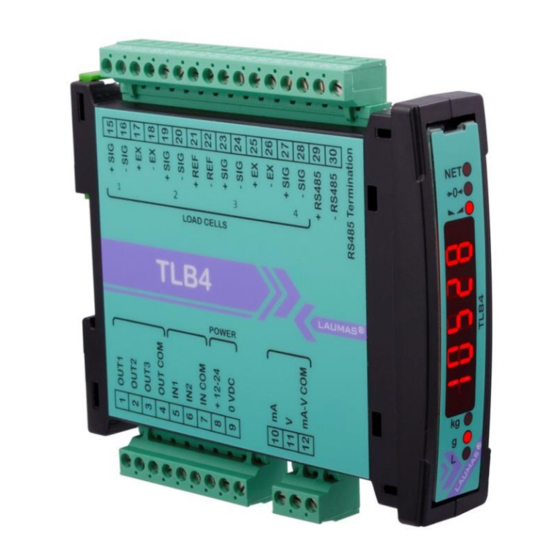
ELECTRICAL CONNECTIONS BASIC INFORMATION - It is recommended that the power supply negative pole be grounded. - It is possible to supply up to 16 350 ohm load cells. - Connect terminal “–SUPPLY” to the RS485 common of the connected instruments in the event that these receive alternating current input or that they have an optically isolated RS485. - Page 11 TERMINALS LEGEND OUTPUT No. 1 17 +LOAD CELLS 1 and 2 EXCITATION (+EX) -LOAD CELLS 1 and 2 EXCITATION (-EX) OUTPUT No. 2 LOAD CELLS SHIELD OUTPUT No. 3 19 +LOAD CELL 2 SIGNAL OUTPUT COMMON 20 -LOAD CELL 2 SIGNAL INPUT No.
-
Page 12: Led And Keys Functions
LED AND KEYS FUNCTIONS Secondary function * Main function net weight (semi-automatic tare or preset tare) LED lit: output 3 closed zero (deviation from zero not more than ±0.25 LED lit: output 2 closed divisions) stability LED lit: output 1 closed unit of measure: kg unit of measure: g LED lit: input 2 closed... -
Page 13: Menu Map
MENU MAP Into menus changes are applied right after pressing the key (no further confirmation is required). SETPOINT … … SYSTEM PARAMETERS ... - Page 14 TLB4 only - 10 -...
-
Page 15: Instrument Commissioning
INSTRUMENT COMMISSIONING Upon switch-on, the display shows in sequence: - → (ONLY in case of approved program); - instrument model (e.g.: ); - followed by the software code (e.g.: ); - program type: (base); - followed by the software version (e.g.: ); - ... -
Page 16: Programming Of System Parameters
PROGRAMMING OF SYSTEM PARAMETERS From the weight display, press simultaneously keys to access the parameter setting. to enter a menu/confirm the data entry. to modify the displayed figure or menu item. to select a new figure or modify the displayed menu item. to cancel and return to the previous menu. -
Page 17: Maximum Capacity
MAXIMUM CAPACITY : maximum displayable weight (from 0 to max full scale; default: 0). When the weight exceeds this value by 9 divisions, the display shows . To disable this function, set 0. TARE WEIGHT ZERO SETTING ... -
Page 18: Zero Value Manual Entry
- Press to display in sequence the load distribution stored during the last zero-setting on each channel ( ÷ ); press to return to the previous display. - Press and select or to store or not the current distribution and the zero mV values (see section TEST). -
Page 19: Real Calibration (With Sample Weights)
REAL CALIBRATION (WITH SAMPLE WEIGHTS) After having performed the THEORETICAL CALIBRATION, EQUALIZATION and TARE WEIGHT ZERO SETTING, this function allows correct calibration to be done using sample weights of known value and, if necessary, any deviations of the indicated value from the correct value to be corrected. -
Page 20: Confirmation And Change Of Active Channels
CONFIRMATION AND CHANGE OF ACTIVE CHANNELS After performing the calibration and verifying that the system works properly, you can confirm the channels automatically detected by the instrument; in this way, in case of accidental interruption of the cable of one or more load cells, the instrument displays the alarm. Automatic load cells detection is enabled by default on all 4 channels of the instrument. -
Page 21: Equalization
EQUALIZATION At the end of the equalization you must perform the TARE WEIGHT ZERO SETTING and, if necessary, the REAL CALIBRATION. REAL EQUALIZATION Use a sample weight equal to at least 50% of the single load cell capacity. : unload the scale, wait for stability and confirm by pressing : place the sample weight on load cell 1, wait for stability and confirm by pressing : place the sample weight on load cell 2, wait for stability and confirm by pressing... -
Page 22: Filter On The Weight
FILTER ON THE WEIGHT Setting this parameter allows a stable weight display to be obtained. To increase the effect (weight more stable) increase the value (from 0 to 9, default 4). As seen in the diagram: - By confirming the message, the currently programmed filter value is displayed. - By changing and confirming the value, the weight is displayed and it will be possible to experimentally verify its stability. -
Page 23: Zero Parameters
ZERO PARAMETERS RESETTABLE WEIGHT SETTING FOR SMALL WEIGHT CHANGES (from 0 to max full scale; default: 300; considered decimals: 300 – 30.0 – 3.00 – 0.300): this parameter indicates the maximum weight value resettable by external contact, keypad or serial protocol. -
Page 24: Setting Units Of Measure
SETTING UNITS OF MEASURE These are the available units of measure: kilograms : grams : tons : pounds* : : newtons* litres* : bars* : atmospheres* : pieces* : newton metres* : : kilogram metres* other generic units of measure not included in the list* : If the print function is enabled, the symbol corresponding to the selected unit of measure will be printed after the measured value. - Page 25 If the unit of measure chosen is: : pounds, the value set in will be multiplied by the weight value currently displayed; : newton, the value set in will be multiplied by the weight value currently displayed; : litres, in set the specific weight in kg/l, assuming that the system is calibrated in kg; : bar, the value set in ...
-
Page 26: Outputs And Inputs Configuration
OUTPUTS AND INPUTS CONFIGURATION … … OUTPUTS The outputs are set by default as follows: / / / / . Possible operation modes: - (normally open): the relay is de-energised and the contact is open when the weight is lower than the programmed setpoint value;... -
Page 27: Semi-Automatic Tare (Net/Gross)
INPUTS Default: input 1 = input 2 = Possible operation modes: - (NET/GROSS): by closing this input for no more than one second, it’s making an operation of SEMI-AUTOMATIC TARE and the display will show the net weight. To display the gross weight again, hold the NET/GROSS input closed for 3 seconds.... -
Page 28: Preset Tare (Subtractive Tare Device)
PRESET TARE (SUBTRACTIVE TARE DEVICE) It is possible to manually set a preset tare value to be subtracted from the display value provided that the ≤ max capacity condition is verified. By default the instrument shows the last programmed preset tare value: to apply it press then After setting the tare value, going back to the weight display, the display shows the net weight (subtracting the preset tare value) and the NET LED lights up to show that a tare has been entered. -
Page 29: Peak
PEAK By keeping the PEAK input closed the maximum weight value reached remains displayed. By opening the input the current weight is displayed. If you wish to use this input to view a sudden variation peak, set the FILTER ON THE WEIGHT to 0. - Page 30 - : analog output correction to zero: if necessary adjust the analog output, allowing the PLC to indicate 0. The sign “-“ can be set for the last digit on the left. E.g.: if I use a 4÷20 mA output and, with the minimum analog setting, the PLC or tester read 4.1 mA, I must set the parameter to 3.9 to obtain 4.0 on the PLC or tester.
-
Page 31: Serial Communication Setting
SERIAL COMMUNICATION SETTING - : it disables any type of communication (default). - : MODBUS-RTU protocol; possible addresses: from 1 to 99 (see Communication protocols manual). - : ASCII bidirectional protocol; possible addresses: from 1 to 99 (see Communication protocols manual). -
Page 32: Rs485 Serial Communication
- : - : no parity (default). - : even parity. - : odd parity. - : stop bit (1 – 2; default: 1). - : number of copies(1 – 9; default: 1). - : number of blank lines between one printout and the next. - : printing of custom heading from PC (... -
Page 33: Direct Connection Between Rs485 And Rs232 Without Converter
DIRECT CONNECTION BETWEEN RS485 AND RS232 WITHOUT CONVERTER Since a two-wire RS485 output may be used directly on the RS-232 input of a PC or remote display or printer, it is possible to implement instrument connection to an RS-232 port in the following manner: INSTRUMENT RS232... -
Page 34: Test
Diagnostics on zero: when a zero-setting is performed from the menu, the instrument calculates the load percentage on each channel; diagnostics on zero is performed only if the load distribution has been stored at least once (see section TARE WEIGHT ZERO SETTING). If with unloaded system the load percentage error is higher than the value set in parameter , the display shows the ... -
Page 35: Events Log
EVENTS LOG The instrument can store up to 50 events; the oldest records are overwritten. - : it displays the last 50 events stored, starting from the most recent one: : zero-setting from the calibration menu, press to display the value set to zero. -
Page 36: Setpoint Programming
SETPOINT PROGRAMMING From the weight display, press to access the setpoint setting. to enter a menu/confirm the data entry. to modify the displayed figure or menu item. to select a new figure or modify the displayed menu item. to cancel and return to the previous menu. ... -
Page 37: Use With W Series Instruments
USE WITH W SERIES INSTRUMENTS WARNING: the weight indicator must be properly configured before operating in combination with the multi-channel weight transmitter (see section DATA DELETION AND PROGRAM SELECTION in W serie instrument manual) and the approval status set on both instruments must be the same. When the TLB4 is used in combination with a W serie instrument, the load cells are connected to the multi-channel weight transmitter, which transmits the weight to the indicator;... -
Page 38: Additional Menu Map
ADDITIONAL MENU MAP WARNING: the map shows only the additional menu items that are enabled on the W series instruments connected to the TLB4. Into menus changes are applied right after pressing the ENTER key (no further confirmation is required). ENTER + ESC ... -
Page 39: Tlb4 Remote Control
TLB4 REMOTE CONTROL The following functions of TLB4 can be performed remotely through the weight indicator: INSTRUMENT COMMISSIONING TARE WEIGHT ZERO SETTING CONFIRMATION AND CHANGE OF ACTIVE CHANNELS EQUALIZATION FILTER ON THE WEIGHT ANTI PEAK ... -
Page 40: Alarms
ALARMS no load cell detected, check the connections. : the load cell signal exceeds 39 mV; the conversion electronics (AD converter) is : malfunctioning. : the references are not connected or are incorrectly connected; the load cell is a 4-wire and there are no jumpers between EX- and REF- and between EX+ and REF+. - Page 41 Serial protocol alarms: MODE The response to the Bit LSB 76543210 76543210 76543210 76543210 76543210 zero command is a On gross: xxxxxxx1 xxxx1xxx xxxxxx1x xxxxx1xx Status “value not valid” error xxx1xxxx Register (error code 3) On net: MODBUS RTU xx1xxxxx...
-
Page 42: Printing Examples
PRINTING EXAMPLES If the printer has been set (see section SERIAL COMMUNICATION SETTINGS), from the weight display press the key: BASIC PRINTOUT ----------------------- TLB4 BASE Addr:01 GROSS 878 kg 589 kg TARE 289 kg BASIC PRINTOUT (PEAK ENABLED): ----------------------- TLB4 BASE Addr:01 GROSS... - Page 43 LOAD DISTRIBUTION PRINT Current distribution: press the key from the menu. Current and stored distribution: from the and menus, keep pressed the key for more than 3 seconds while the weight is displayed. CURRENT DISTRIBUTION ----------------------- TLB4 BASE Addr:01 CURRENT...
-
Page 44: Front Panel Mounting
FRONT PANEL MOUNTING TLB4 can be installed on front panel using the included mounting kit: - drilling size: 23x96 mm - maximum panel thickness: 2.5 mm Pull out the terminal strips and insert the instrument into the hole. Insert the mounting brackets into the housings, on both sides of the instrument. Tighten the four screws up to lock the instrument. -
Page 45: Reserved For The Installer
RESERVED FOR THE INSTALLER MENU LOCKING Through this procedure, it’s possible to block the access to any menu on the instrument. Select the menu that you wish to lock: press simultaneously for 3 seconds, the display shows (the left point on the text indicates that this menu item is now locked). -
Page 46: Keypad Or Display Locking
PROGRAM SELECTION: confirm and use the arrow keys to select the desired program: : basic program, setpoint management only. : to be used when the loaded weighing system correspond to not loaded cells and vice versa (product increases while weight on load cells actually decreases). : weight remote display program with setpoint. -
Page 47: Declaration Of Conformity - Eu
CERTIFICAZIONE DEL SISTEMA DI GARANZIA DELLA QUALITÀ DELLA PRODUZIONE email: laumas@laumas.it web: http://www.laumas.com LAUMAS Elettronica S.r.l. Tel. (+39) 0521 683124 - Fax (+39) 0521 681091 Fabbricante metrico Prot. N. 7340 Parma - R.E.A. PR N. 169833 - Reg. Imprese Via 1° Maggio 6 – 43022 Montechiarugolo (PR) Italy PR N.19393 - Registro Nazionale Pile N°...