Table of Contents
Advertisement
Advertisement
Table of Contents

Related Manuals for Volvo Penta D9-425


Summary of Contents for Volvo Penta D9-425
- Page 1 OPERATOR’S MANUAL D9-425, D9-500, D9-575...
- Page 2 This operator’s manual is also available in the following languages: Diese Betriebsanleitung ist auch auf Dit instructieboek kan worden besteld Deutsch erhältlich. in het Nederlands. Ein Bestellcoupon ist am Ende der Betriebs- De bestelcoupon vindt u achter in het instruc- anleitung zu finden.
- Page 3 Welcome aboard Volvo Penta marine engines are used all over the world these days. They are used in all conceivable operating conditions and by both professional and leisure skippers. This is not a coincidence. After 90 years as an engine manufacturer, and more than 500,000 marine engines supplied, the name of Volvo Penta has come to symbolise reliability, technical inno- vation, first class performance and long life.
-
Page 4: Table Of Contents
Changing the control position ......28 Operation ............29 Propeller shaft brake ........... 30 © 2004 AB VOLVO PENTA We reserve the right to make modifications without prior notice. Printed on environmentally compatible paper. (Cover: Department of transport (shipping), license 9809095) -
Page 5: Safety Information
If there is still something which is unclear or if you feel un- sure about it, please contact your Volvo Penta dealer for assistance. This symbol is used in the instruction book and on the product, to call your attention to the fact that this is safety information. -
Page 6: Boat Trips
Safety information Safety advice for boat operation Manoeuvring Your new boat Read the instruction books and other information care- Avoid sudden or surprising rudder movements and fully, which came with your new boat. Learn to handle gear shifting. There is a risk that passengers could fall the engine, controls and other equipment in a safe and over, or overboard. - Page 7 Safety information Carbon monoxide poisoning When a boat moves forwards, an area of low pressure Most modern boats are designed so that the problem air forms behind the boat. In adverse conditions, this of low-pressure suction is very rare, however. If low- low pressure can be so strong that the boat’s own ex- pressure suction does occur anyway, do not open haust fumes are sucked into the cockpit or cabin,...
-
Page 8: Care And Maintenance
Never do a job if you are not entirely sure about how to do Store oil and fuel soaked rags and other flammable it. Contact a Volvo Penta dealer for assistance instead. material in a fire-proof manner. Oil soaked rags can self-ignite in certain circumstances. - Page 9 Safety information Hot surfaces and fluids Fuel system A hot engine always offers the risk of burns. Be on Always protect your hands when searching for leaks. your guard against hot surfaces, such as the ex- Fluids which leak under pressure can force their way haust manifold, turbocharger, sump, charge air pipe, into body tissue and cause severe injury.
-
Page 10: Introduction
Introduction This instruction book has been prepared to give you the greatest possible benefit from your Volvo Penta marine engine. It contains the information you need to be able to operate and maintain the engine safely and correctly. Please read the instruction book carefully and learn to handle the engine, controls and other equipment in a safe manner before you cast off on your maiden voyage. -
Page 11: Certified Engines
If this is not done, AB Volvo Penta may fully or partly refuse to honour its warranty undertakings. Please contact your Volvo Penta dealer if you have not received a Warranty and Service book, or... -
Page 12: Identification Number
Introduction Identification numbers There are type plates on the engine and transmission, marked with identification numbers. This information must always be used as reference when service and spare parts are ordered. You will probably find similar plates on your boat and its equipment. Note this information below, make a copy of the page and store it in a safe place, so that you can have the information available if the boat is stolen. -
Page 13: Presentation
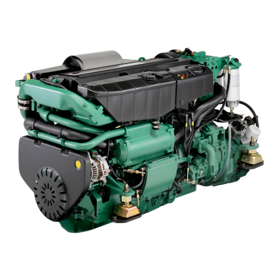
Presentation The D9 in-line diesel has a robust block with ladder frame, high pressure unit injector system, 4 valves per cylinder, “twin entry” turbo and charge air cooler. Together with a large swept volume and the EVC (Electronic Vessel Control), this results in a very smooth running engine with world-class diesel performance, combined with low fuel consumption and emissions. -
Page 14: Orientation
Presentation Orientation D9-575 ZF305 Expansion tank Coolant filler cap Emergency stop Crankcase breather filter Fuel feed pump (hand pump) Fine fuel filter with watertrap Alternator Heat exchanger Control unit 10. Oil sump 11. Seawater pump 12. Reverse gear ZF305A-E D9-575 ZF305 By-pass filter for lubrication oil Lubrication oil filter Water-cooled exhaust outlet... - Page 15 Presentation D9-500 ZF280 Expansion tank Coolant filler cap Emergency stop Crankcase breather filter Fuel feed pump (hand pump) Fine fuel filter with watertrap Alternator Heat exchanger Control unit 10. Oil sump 11. Seawater pump 12. Reverse gear ZF280A-E D9-500 ZF280 By-pass filter for lubrication oil Lubrication oil filter Water-cooled exhaust outlet...
- Page 16 Presentation D9-500 MG5075 Expansion tank Coolant filler cap Emergency stop Crankcase breather filter Fuel feed pump (hand pump) Fine fuel filter with watertrap Heat exchanger Aftercooler Control unit 10. Oil sump 11. Seawater pump 12. Reverse gear MG5075A-E D9-500 MG5075 By-pass filter for lubrication oil Lubrication oil filter Water-cooled exhaust outlet...
-
Page 17: Instruments
Instruments This chapter describes the instrument and control panels sold by Volvo Penta for your engine. If you want to supplement the instrumentation, or if your boat is equipped with instruments not described here, or you are not sure about their function, please contact your Volvo Penta dealer. -
Page 18: Alarm Display
Instruments Alarm display The following warning lamps should never light up during operation. On the other hand, the warning lamps light up when the starter key is first turned to the drive position. Check that all lamps function. When the engine has started, all lamps should have gone out. - Page 19 Instruments Battery. (orange indication) The battery lamp lights up if the alternator is not charging. Stop the engine if this lamp lights up during operation. If the lamp lights up, this can be due to a fault in the electrical system or because the alternator drive belt is slack.
- Page 20 Instruments Coolant level (orange indication) The coolant lamp lights up when the coolant level is too low. Check coolant level. Please refer to “Maintenance: Lubrication system”. Please refer to the “If something happens” chapter, and you will find detailed information about recommen- ded action in the “Diagnostic function”...
-
Page 21: Evc Control Panel
Instruments EVC control panel There are two versions of the EVC control panel, one for single engine installations and another for twin installations. Activation button Synchronization indication Used to activate the control panel, so that the engine The synchronization function automatically adjusts the can be started and stopped. - Page 22 Instruments EVC-Display (extra optional) The Volvo Penta EVC-display is an on-board instru- ment for indication of engine operating values. The display consists of a self-contained, computerised unit for fixed installation in a control panel. Indications are presented on a Liquid Crystal Display (LCD) screen.
-
Page 23: Controls
Controls This chapter describes the instrument panels sold by Volvo Penta for your engine. If your boat is equipped with controls which are not described here and you feel uncertain about the function, please contact the dealer you purchased the boat from. - Page 24 Controls Friction brake The control is also equipped with a friction brake which can be adjusted for easier or stiffer lever movement as necessary. Friction brake adjustment: 1. Stop the engine. 2. Move the control lever forwards to make the groove in the control lever hub accessible.
-
Page 25: Starting The Engine
Starting the engine Make it a habit to give the engine and engine bay a visual check before starting. This will help you to discover quickly if anything abnormal has happened, or is about to happen. Also check that instruments and warning dis- plays show normal values after you have started the engine. -
Page 26: Starting Method
Starting the engine Starting method Put the reverse gear in neutral Put the reverse gear in neutral by moving the control lever(s) to neutral at all control positions. Two lever control: Also check that the engine speed lever is in the idling position. Turn the ignition on Turn the starter key to position I to switch the ignition on. - Page 27 Starting the engine Start the engine Start using the ignition switch Turn the key to position III. Release the key and let it key spring back to position I as soon as the engine has started. NOTE! If repeated start attempts are needed, the key must be turned back to position 0 first.
-
Page 28: Operation
Operation Learn to handle the engine, controls and other equipment in a safe and correct manner before you cast off on your maiden voyage. Remember to avoid sudden or surprising rudder movements and gear shifting. There is a risk that passengers could fall over, or overboard. -
Page 29: Cruising Speed
“Fault tracing” chapter. If the engine speed exceeds the full throttle range, select a coarser pitch propeller. Ask your Volvo Penta dealer for advice. Synchronizing engine speed When driving with twin engines, both the operating economy and comfort can be increased when the engines are opera- ting at the same engine speed (rpm). -
Page 30: Changing The Control Position
This function must be enabled to permit the control panel to be changed during operation. The function can only be ena- bled by authorized Volvo Penta personnel. Please contact your Volvo Penta dealer. 1. Press the activation button (1) to unlock the system. -
Page 31: Operation
Operation Operation Shifting between forward and reverse should be done at id- ling. Shifting at higher engine speeds can be uncomfortable for passengers and cause unnecessary stress on the stern drive/reverse gear, or cause the engine to stop. If you attempt to shift gear at an excessive engine speed, a safety function cuts in automatically, and delays shifting until engine speed has fallen to 1000 rpm. -
Page 32: Stopping The Engine
Stopping the engine Allow the engine to idle (in neutral) for at least three minutes after the end of your journey. This evens out the temperatures inside the engine, and stops after-boiling. IMPORTANT! The above is particularly important if the engine has been driven at high speed and/or heavily loaded. -
Page 33: Cold Weather Precautions
Stopping the engie Cold weather precautions If the engine bay can not be kept frost-free, the sea- water system must be drained and the freshwater sys- tem coolant must have enough anti-freeze to prevent frost damage. Please refer to the “Seawater system” and “Freshwater system”... -
Page 34: In Case Of Emergency
In case of emergency Despite regular maintenance according to the maintenance schedule and perfect operation, it may occur that a fault occurs which must be attended to before the boat can travel further. This chapter contains tips for rectifying some of the possible faults. There are safety functions which are activated when certain faults occur, to protect the engine. -
Page 35: Emergency Shifting
In case of emergency Emergency shifting If a fault occurs which prevents the revers gear from being operated (shifted) with the control lever, it is possible to shift manually, using the description below. Note. The descriptions refer to electrically shifted re- vers gear. -
Page 36: Fault-Tracing
A number of symptoms and possible causes of engine malfunctions are described in the table below. Always con- tact your Volvo Penta dealer if problems occur which you can not solve by yourself. WARNING! Read through the safety advice for care and maintenance work in the “Safety information” chap- ter before starting work. -
Page 37: Diagnostic Function
In case of emergency Diagnostic function The diagnostic function monitors and checks that the engine, stern drive/reverse gear and EVC system function normally. The diagnostic function has the following tasks: ● Discover and localize malfunctions ● Notify that malfunctions have been discovered ●... -
Page 38: Reading Fault Codes
In case of emergency Fault codes The fault codes are flashed out on the diagnostic button indication. The fault code consists of three groups of flashes, separated by a pause of two seconds. A fault code is obtained by counting the num- ber of flashes in each group: Example: pause... -
Page 39: Erasing Fault Codes
In case of emergency Erasing fault codes Any fault codes in the diagnostic function are automatically erased every time the starter key is tur- ned to the stop position (S). NOTE! Stop the engine and check that the ignition key(s) is(are) in position 0 in all control positions. When system voltage is switched on again, the diagnostic function checks to see whether there are any faults in the EVC system. -
Page 40: Maintenance Schedule
Maintenance schedule General information Your Volvo Penta engine and its equipment are designed for high reliability and long life. They are built to with- stand a marine environment, but also to have the smallest possible environmental impact. If given preventive maintenance, according to the maintenance schedule, and if Volvo Penta original spares are used, these qualities are retained and unnecessary malfunctions can be avoided. - Page 41 Maintenance schedule Every 200 hours / at least every 12 months ● Fuel pre-filter (twin filter). Inspection ..............page 58 Only applies to the double filter: Check the pressure gauge and change the filter as necessary every 800 hours of operation, or at least once every 12 months. Every 400 hours / at least every 12 months ●...
-
Page 42: Maintenance
Maintenance This chapter contains general technical information and instructions for carrying out the specified maintenance points. Read them carefully before starting work. The times when maintenance points need to be attended to are given in the previous chapter: Maintenance schedule WARNING! Read through the safety advice for care and maintenance work in the Safety information chap- ter before you start work. - Page 43 Maintenance. Engine, general Crankcase ventilation. Changing the filter Remove the air filter cover. Remove the old air filter. Clean the air filter cover/housing if necessary. Take care not to allow impurities to enter the engine. Fit the new air filter and the air filter cover. Changing the air filter Remove the air filter cover.
- Page 44 Maintenance. Engine, general Drive belts. Inspection/adjustment WARNING! Stop the engine before doing any maintenance work. General information Check belt tension and condition regularly. A belt which is to tense can damage the bearings and a belt which is too loose can slip. IMPORTANT! Always change a belt which looks worn or cracked (belts which operate in pairs must be changed together).
-
Page 45: Lubrication System
Maintenance. Lubrication system Lubrication system Oil change intervals can vary from 50 to 400 hours, depending on oil grade and sulphur content of the fuel. Note that oil change intervals must never exceed a period of 12 months. If you want longer oil change intervals than given in the table below, the condition of the oil must be checked by the oil manufacturers through regular oil testing. - Page 46 Maintenance. Lubrication system Oil level. Checking and filling The oil level must be inside the marked area on the dipstick and should be checked daily before the first start. Top up the oil through the filling hole on the side of the engine (1) .
- Page 47 Maintenance. Lubrication system Oil filter and bypass filter. Change Change the oil filter and bypass filter during each oil change. Remember to hand the old filters in to a re-cycling station. WARNING! Hot oil and hot surfaces can cause burns. 1.
-
Page 48: Freshwater System
The coolant should contain ethylene glycol of a good quality with a suitable chemical consistency for an adequate protection of the engine. Using anti-corrosion aditive exclusively is not permitted in Volvo Penta’s engines. Never use water by itself as coolant. - Page 49 (18°F). (Using 60 % glycol lowers the freezing point to -54 °C (65°F)). Never mix more than 60 % concentrate (Volvo Penta Coolant) in the cooling liquid, this will give reduced cooling effect and increase the risk of overheating, and will give reduced freezing protection.
- Page 50 Maintenance. Freshwater system Coolant level. Inspection WARNING! Never open the pressure cap when the engine is hot. Steam or hot coolant can spray out at the same time as the pressure which has built up is lost. The coolant level should be about five centimetres (2”) be- low the pressure cap sealing plane in the expansion tank.
- Page 51 Maintenance. Freshwater system 3. Fill up with coolant via the filling hole on the ex- pansion tank. Fill slowly, to allow the air which is forced out a chance to flow out of the filling hole. 4. Fill up with coolant to about 5 cm (2") below the filling cap seal plane.
- Page 52 Maintenance. Freshwater system Freshwater system. Flushing The cooling system should be flushed when the cool- ant is changed, to avoid loss of cooling performance due to deposits in the cooling system. 1. Drain the coolant, as in the description on the pre- vious page.
-
Page 53: Seawater System
Maintenance. Seawater system Seawater system The seawater system is the engine’s external cooling system. The seawater system sucks in water through the seawater inlet and pumps it through the heat exchanger and the reverse gear oil cooler. The system is protected from galvanic corrosion by means of zinc anodes located in the heat exchanger and the reverse gear oil cooler. - Page 54 Maintenance. Seawater system Zinc anodes. Check/change WARNING! Risk of water entry. Close the sea cock before doing any work on the seawater system. 1. Close the sea cock. 2. Open the drain tap (1) on the heat exchanger and the tap (2) on the charge air cooler, and drain off the seawater.
- Page 55 Maintenance. Seawater system Impeller. Check/change WARNING! Risk of water entry. Close the sea cock before doing any work on the seawater system. 1. Remove the seawater pump lid, and pull the im- peller out with water pump pliers. 2. Check the impeller. If any cracks or other defects are visible, the impeller must be changed.
- Page 56 Maintenance. Seawater system Inlet manifold. Checking the drain hole Water can condense in the aftercooler during opera- tion. The condensate is drained via a hole in the charge air cooler. Check that the drain hole is not blocked. WARNING! If a large amount of water flows out of the drain hole, from the inlet manifold, the af- tercooler must be removed and proof tested.
- Page 57 Maintenance. Seawater system Heat exchanger. Cleaning This job requires specialist knowledge, and should be done by an authorised workshop. WARNING! Risk of water entry. Close the sea cock and drain off the water in the seawater and freshwater systems before doing any work on the cooling system.
-
Page 58: Fuel System
Maintenance. Fuel system Fuel system Only use the grades of fuel recommended in the fuel specification, see Technical Data. Always observe the great- est cleanliness during re-fuelling and work on the fuel system. All work on the unit injectors of the engine must be carried out by an authorised workshop. WARNING! Fire hazard. - Page 59 Maintenance. Fuel system Change the filter elements 1. Close the fuel valve/valves. 2. Clean the filter bracket and put a suitable vessel under the filter. 3. Relieve pressure inside the filter by first opening the drain tap (1) at the bottom of the water trap and then the venting nipple (2) so the filter is drained off fuel.
- Page 60 Maintenance. Fuel system Fuel pre-filter The fuel pre-filter supplied by Volvo Penta is available in single and twin versions. Fuel pre-filter. Inspection This filter is equipped with a pressure gauge (1) which indicates when it is time to change the filter insert.
- Page 61 Maintenance. Fuel system Change the filter elements If the engine is not running close the fuel cocks on the tank before changing filters. If the engine is running cut off the flow of fuel with the handle (1) on the filter itself.
-
Page 62: Electrical System
IMPORTANT ! Always investigate the cause of the overload! Electrical connections Check that electrical connections are dry, free from oxide and that they are securely tightened. Spray these connections as necessary with water-repellent spray (Volvo Penta universal oil). - Page 63 Maintenance. Electrical system Batteries. Maintenance WARNING! Fire and explosion hazard. Batteries must never be exposed to open flames or sparks. WARNING! Never confuse the positive and neg- ative poles on the batteries. Risk of arcing and explosion. WARNING! Battery electrolyte is highly corro- sive.
- Page 64 Maintenance. Electrical system Batteries. Charging WARNING! Explosion risk! Hydrogen is given off when batteries are charged. This forms an ex- plosive mixture with air. A short circuit, open flame or spark could cause a violent explosion. Ventilate well. WARNING! Battery electrolyte is highly corro- sive.
- Page 65 Maintenance. Electrical system Electric welding Remove the positive and negative cables from the batteries. Then disconnect all cables connected to the alternator. Also undo the connector for the EVC system from the control unit.Press the lock tab down and pull the connector out.
- Page 66 Maintenance. Electrical system 3. Protective earth cables for radio, navigation equip- ment, rudder, bathing steps etc., or other equip- ment which uses protective earthing, shall be con- nected to a common earthing point which is not connected to the engine or reverse gear. IMPORTANT! The engine and reverse gear must never be used as earth planes.
-
Page 67: Reverse Gear
Maintenance. Reverse gear Reverse gear Oil level. Checking and filling Inspection Check the oil level when the reverse gear has reached operating temperature, with the engine idling and the control lever in neutral. WARNING! Working with, or going close to a running engine is a safety risk. - Page 68 Maintenance. Reverse gear Oil. Change 1. Remove the dipstick. Connect a hose from the oil scavenging pump to the dipstick tube. 2. Suck the oil up and put the dipstick back. 3. Fill up with oil to the correct level. Oil grade and vol- ume: Please refer to the “Technical Data”...
-
Page 69: Laying Up/Launching
Before the boat is taken out of service for a long period of time, an authorised Volvo Penta workshop should over the engine and other equipment. Have any faults and deficiencies attended to, so that the equipment is in order, ready for the next start. -
Page 70: Bringing Out Of Storage
Laying up/Launching Bringing out of storage ● Remove any covers from the engine, air inlet and ● Insert the impeller in the seawater pump, using a exhaust pipe. rotating movement (anti-clockwise). ● Top the engine up with the correct grade of oil, if ●... -
Page 71: Fault Code Register
Reaction: None Action: • Empty the water trap underneath the fuel filters. Please refer to “Maintenance: Fuel system” • Contact a Volvo Penta workshop if the fault remains. 1.2.2 Explanation: Coolant level too low. Reaction: Engine power is reduced. Action: •... - Page 72 Explanation: Fault in engine speed sensor on flywheel. Reaction: Engine power is reduced. Engine is difficult to start. Action: • Please contact a Volvo Penta workshop. 1.2.5 Explanation: Fault in engine speed sensor on camshaft. Reaction: Engine is difficult to start.
- Page 73 Check that the oil filters are not blocked. Please refer to “Maintenance: Lubrication system”. • Check that no leakage occurs. • Contact a Volvo Penta workshop if the fault remains. 1.5.6 Explanation: Charge air pressure too high. Reaction: Engine power is reduced.
- Page 74 Check that the oil filters are not blocked. Please refer to “Maintenance: Lubrication system”. • Check that no leakage occurs. • Contact a Volvo Penta workshop if the fault remains. 1.6.1 Explanation: Excessive coolant temperature . Reaction: Engine power is reduced.
- Page 75 • Check the oil level in the engine. Please refer to “Maintenance: Lubrication system” to check and top the oil up. • Check the oil filters. Please refer to “Maintenance: Lubrication system”. • Check that no leakage occurs. • Contact a Volvo Penta workshop if the fault remains. 1.6.9 Explanation: Sea water pressure too low.
- Page 76 Check that the oil strainer is not blocked. Please refer to “Maintenance: Lubrication system” • Check that no leakage occurs. • Please contact a Volvo Penta workshop if the fault remains. 2.4.5 Explanation: Faulty solenoid, primary. Reaction: Can not engage a gear.
- Page 77 Action: • Check that the control lever is connected. • Check that the lever combination is approved by Volvo Penta. • Please contact a Volvo Penta workshop if the fault remains. 3.1.3 Explanation: Too short lever movement between calibration points.
- Page 78 Explanation: Fault in EVC control panel. Reaction: EVC control panel is out of order. Action: • If the engine can not be operated from the chosen control panel, use an alternative control panel. • Please contact a Volvo Penta workshop.
-
Page 79: Technical Data
Technical data General Type designation ..........D9-425 A, D9-500 A, D9-575 A Number of cylinders ........Displacement ..........9.36 dm , (571 in Low idle speed ..........550 (±25) rpm* Valve clearance,, stationary, cold engine: Setting values, inlet ............0.30 mm (0.0118") exhaust ............ - Page 80 Technical data Lubricating system Oil capacity including oil filters, approx., no engine inclination ........31 liters (8.2 US gals) engine inclination 6 ......... 20 liters (5.3 US gals) Oil pressure, hot engine, at normal running rpm ........390 kPa (56.5 PSI ) at idling rpm (min.) ...........
-
Page 81: Reverse Gear
Technical data Reverse gear Type designation 280A E 280IV Gear ratios 1,48:1; 1,77:1; 2,00:1 1,56:1; 1,77:1 Angle (output shaft) 7° 14° Oil capacity, approx 3,6 liter (0.9 US gal) 5,5 liter (1.4 US gal) Oil grade (in accordance with API-system) CD, CE, CF, CF-4,CG-4,CH-4, CD, CE, CF, CF-4,CG-4,CH-4, CI-4, SF, SG, SH,SJ, SL,... - Page 82 Notes ..............................................................................................................................................................................................................................................................................................................................................................................................................................................................................................................................................................................................................................................................................................................................................................................................................................................................................................................................................................................................................
- Page 83 ✂ Yes please, I would like an operator’s manual in English at no charge. Publication number: 7744682 Post or fax this coupon to: Document & Distribution Center Name Order Department ARU2, Dept. 64620 Address SE-405 08 Göteborg Sweden Fax: +46 31 545 772 Orders can also be placed via the Internet: http://www.volvopenta.com/...
- Page 84 ✂ Sí gracias, deseo recibir gratuitamente un libro de instrucciones en español. Número de publicación: 7743791 Franquear o enviar fax a: Document & Distribution Center Nombre Order Department ARU2, Dept. 64620 Dirección SE-405 08 Göteborg Suecia Fax: +46 31 545 772 El pedido puede hacerse tam- bién por internet: http://www.volvopenta.com/...
- Page 85 ✂ Ja graag, Ik wil kosteloos een instructieboek in het Nederlands ontvangen. Publicatienummer: 7743795 Stuur of fax de coupon naar: Document & Distribution Center Naam Order Department ARU2, Dept. 64620 Adres SE-405 08 Göteborg Zweden Fax: +46 31 545 772 U kunt ook bestellen via internet: http://www.volvopenta.com/...
- Page 86 ✂ Sim, obrigado(a)! Gostaria de receber gratuitamente um manual de instruções em português. Número de publicação: 7743796 Envie o talão pelo correio ou um fax para: Nome Document & Distribution Center Order Department Endereço ARU2, Dept. 64620 SE-405 08 Göteborg Sweden Fax: +46 31 545 772 A encomenda também pode...