Advertisement
Quick Links
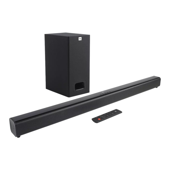
SB130
2.1CH Soundbar with Wired Subwoofer
SKU:
JBLSB130BLKIN
JBLSB130BLKAS
JBLSB130BLKEP
JBLSB130BLKUK
JBLSB130BLKAM
JBLSB130BLKBR
Released by Global Quality 2019
SPECIFICATIONS:
・
Power supply: 100 - 240V~, 50/60Hz
Total maximum power : 110 W
Soundbar maximum output power: 2 x 27 W
Subwoofer maximum power: 56 W
Max SPL: 82dB
Frequency response : 40Hz - 20KHz
Soundbar dimensions (W x H x D) : 900 x 67 x 63 mm / 35.4" x 2.6" x 2.5"
Soundbar weight: 1.5 kg
Subwoofer dimensions (W x H x D) : 150 x 320 x 220 mm / 6" x 12.6" x 8.7"
Subwoofer weight: 2.8 kg
CONTENTS
Safety Instruction ...................................................................................... 2
Special Information BGA IC & Flat Pack-IC................................................ 5
Software upgrade Instruction & Reset Procedure ....................................8
Disassembly Instruction ............................................................................ 9
Block Diagram.......................................................................................... 11
Circuit Diagarms & PCBA Layout ............................................................ 12
Mechanical Exploded View .................................................................... 16
Spare Parts List ....................................................................................... 18
Revision List ............................................................................................ 19
Service Manual
harman/kardon, Inc.
Rev. 1.1 Jan/2020
Advertisement

Related Manuals for JBL SB130


Summary of Contents for JBL SB130
- Page 1 Service Manual SB130 2.1CH Soundbar with Wired Subwoofer SPECIFICATIONS: SKU: ・ Power supply: 100 - 240V~, 50/60Hz JBLSB130BLKIN Total maximum power : 110 W JBLSB130BLKAS JBLSB130BLKEP Soundbar maximum output power: 2 x 27 W JBLSB130BLKUK Subwoofer maximum power: 56 W...
- Page 2 Important Safety Instructions 1. Read these instructions. CAUTION 2. Keep these instructions. 3. Heed all warnings. RISK OF ELECTRIC SHOCK. DO NOT OPEN. 4. Follow all instructions. 5. Do not use this apparatus near water. 6. Clean only with a dry cloth. 7.
- Page 3 Some semiconductor (solid state) devices can be damaged easily by static electricity. Such components commonly are called Electrostatically Sensitive (ES) Devices. Examples of typical ES devices are integrated circuits and some field effect transistors and semiconductor "chip" components. The following techniques should be used to help reduce the incidence of component damage caused by static electricity. 1.
- Page 4 SAFETY PRECAUTIONS The following check should be performed for the continued protection of the customer and service technician. LEAKAGE CURRENT CHECK Measure leakage current to a known earth ground (water pipe, conduit, etc.) by connecting a leakage current tester between the earth ground and all exposed metal parts of the appliance (input/output terminals, screwheads, metal overlays, control shaft, etc.).
- Page 5 Special Information of BGA IC & Flat Pack-IC Special information for BGA-ICs: How to Remove / Install Flat Pack-IC • - lead free BGA-ICs will be delivered in so-called 1. Removal 'dry-packaging' (sealed pack including a silica gel pack) to protect the IC against moisture. After With Hot-Air Flat Pack-IC Desoldering Machine: opening, dependent of MSL-level seen on indicator- 1.
- Page 6 Special Information of BGA IC & Flat Pack- IC 3. The flat pack-IC on the CBA is affixed with glue, so With Iron Wire: be careful not to break or damage the foil of each 1. Using desoldering braid, remove the solder from pin or the solder lands under the IC when all pins of the flat pack-IC.
- Page 7 Special Information BGA IC & Flat Pack-IC Instructions for Handling Semi- 2. Installation conductors 1. Using desoldering braid, remove the solder from the foil of each pin of the flat pack-IC on the CBA Electrostatic breakdown of the semi-conductors may so you can install a replacement flat pack-IC more occur due to a potential difference caused by easily.
- Page 8 Reset and Firmware Upgrade Procedure How to Reset/Factory restore? Step1: Soundbar connect the power enter standby mode. Step2: press and hold the “Power“ & "Source" buttons on the soundbar at the same time. Step3: waiting for 2~3 seconds, the Soundbar indicator will flash and all the setting has being reset.
- Page 9 Disassembly procedure a. Tools: White Screw driver scraper knife b1. Take out the Main board of soundbar: 1. Loosen the 4pcs back panel screws, pull out the back panel; 2. Disconnect the cables which are connected with main board; (add some white oil on the black glue and wait for 15 seconds of melting time, that will make it easier to disconnect the cable.
- Page 10 Follow above steps: pour some white oil in the Gap between the plastic and iron grill and wait for 15 seconds of melting time, then use the scraper knife insert into the gap to prize up the iron grill. Disassemble the Speakers : After loosen the 4pcs screws fixed on the Speaker, then could take out it.
- Page 11 SET BLOCK DIAGRAM W25Q16 SPI FLASH MCU5V A3.3V A3.3V AC6901 15W/8Ω@1%THD BT Module Bluetooth 4.2 UART TX/RX TAS5825M 15W/8Ω@1%THD SPHE8109 A3.3V MCU_3.3v MCU_3.3V OPT SPDIF OPTICAL IN 30W/4Ω@1%THD TAS5825M SPDIF HDMI-SPDIF buffer A3.3V 1.2V 1.5/10P MCU_5V A3.3V MCU_5V DC/DC KEY/GND LED*5 KEY*5 IA6003-33...
- Page 12 Main Board -- Circuit Diagram R31 NC HD_SPDIF SW_DET 74LVC2GU04 A3.3V DC_DC SPDIF_IN C33 47 C34 103 FB/600 A3.3V COAXIAL SPDIF_IN1 MCU_5V WPM3407 100u/10V SPDIF_IN1 A3.3V A1.25V A3.3V VOUT POWER 无铅标志 4K7* R71 1K 94V0 标志 100u/10V MCU_5V 8.2K* VCC2 10uH/2.5A IA6006-ADJ FB/DIP-50...
- Page 13 Main Board -- Circuit Diagram Wireless C114 CB13 R117 NC OUT_R WF_3.3V A3.3V 3.3V I2S_OUT_LRCK WF_RX R118 NC LRCK 5V_1808 OUT_L WF_TX CB15 I2S_OUT_DATA1 S_DI/M_DO C121 C117 C118 C120 R115 MSDA VREF VINR S_DO/M_DI CB16 I2S_OUT_BCK R116 NC MSCL AGND VINL BLED A3.3V...
- Page 14 Main Board -- Layout Diagram...
- Page 15 Key Board & LED board -- Circuit & Layout Diagram 无铅标志 MCU_3.3V C401 C402 L400 94V0 标志 FB/1K IR400 R406 R407 R408 R409 R410 L401 C403 FB/1K REMOTE LED400 LED401 LED402 LED403 LED404 LED-R LED-B LED-O LED-W LED-R MCU_3.3V CN401 CN402 MCU_3.3V ADKEY1...
- Page 16 Soundbar Exploded View POSITION PART NUMBER PART NAME 201004569 LEFT SIDE COVER 204001978 EVA PAD 201004572 PC TUBE 201004543 REAR CABINET 200001957 COOLING FIN 201004570 RIGHT SIDE COVER 200001944 IRON GRILL 204003560 INDICATOR FILTER 201004571 PLASTIC KEY CABINET 204003673 SILICONE BOTTON 113000284 SPEAKER 2"8Ω20W 204003556...
- Page 17 Subwoofer Exploded View POSITION PART NUMBER PART NAME 201001928 AIR TUBE 200001974 LOGO PANEL 105001463 WOOD CASE 113000270 SUBWOOFER 4"4Ω30W 101000182 CONNETION CABLE 204000600 SILICONE FOOT...
- Page 18 IC W25Q16JVSSIQ(208MIL) SB110/130/160 U7 IN MAIN PCBA 112000429 #IC SPHE8109S-A (QFN-88) SB110/130/160 U9 IN MAIN PCBA 100002472 22# MAIN PCBA TO LEFT SPEAKER SB130 100002473 22# MAIN PCBA TO RIGHT SPEAKER SB130 101000182 CONNECTION WIRE SB130 105001463 WOOD CASE SB130 113000270 SUBWOOFER 4"4Ω30W SB130...
- Page 19 Revision List Version 1.0 *Initial Release Apr. 2019 Version 1.1 *Update Spare Parts List for new SKU Jan. 2020 11-1...