Sharp MD-E9000H Service Manual
Md compact component system
Hide thumbs
Also See for MD-E9000H:
- Operation manual (52 pages) ,
- Operation manual (148 pages) ,
- Service manual (104 pages)
Table of Contents
Advertisement
Quick Links
SAFETY PRECAUTION OF MD SECTION FOR SERVICE MANUAL .............................................................................. 2
SAFETY PRECAUTION OF CD SECTION FOR SERVICE MANUAL .............................................................................. 3
IMPORTANT SERVICE NOTES (FOR U.K. ONLY) .......................................................................................................... 4
SPECIFICATIONS ............................................................................................................................................................. 4
NAMES OF PARTS ........................................................................................................................................................... 5
OPERATION MANUAL ...................................................................................................................................................... 7
DISASSEMBLY ................................................................................................................................................................ 12
REMOVING AND REINSTALLING THE MAIN PARTS ................................................................................................... 15
TEST MODE .................................................................................................................................................................... 17
ADJUSTMENT ................................................................................................................................................................. 22
ERROR MESSAGE LIST ................................................................................................................................................. 32
EEPROM WRITING PROCEDURE ................................................................................................................................. 33
NOTES ON SCHEMATIC DIAGRAM .............................................................................................................................. 37
TYPES OF TRANSISTOR AND LED ............................................................................................................................... 37
BLOCK DIAGRAM ........................................................................................................................................................... 38
WIRING SIDE OF P.W.BOARD ....................................................................................................................................... 42
SCHEMATIC DIAGRAM .................................................................................................................................................. 52
VOLTAGE ........................................................................................................................................................................ 64
WAVEFORMS OF CD CIRCUIT ...................................................................................................................................... 65
WAVEFORMS OF MD CIRCUIT ..................................................................................................................................... 66
TROUBLESHOOTING ..................................................................................................................................................... 68
FUNCTION TABLE OF IC ................................................................................................................................................ 76
FL DISPLAY ..................................................................................................................................................................... 90
PARTS GUIDE/EXPLODED VIEW
All manuals and user guides at all-guides.com
SERVICE MANUAL
MD COMPACT COMPONENT SYSTEM
CONTENTS
SHARP CORPORATION
MD-E9000H
MODEL
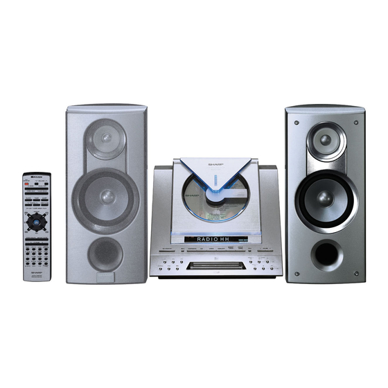
MD-E9000H MD Compact Component System consisting
of MD-E9000H (main unit) and CP-E9000H (speaker
system).
• In the interests of user-safety the set should be restored to its
original condition and only parts identical to those specified should
be used.
This document has been published to be used
for after sales service only.
The contents are subject to change without notice.
MD-E9000H
No. S8151MDE9000H
Page
Advertisement
Table of Contents

Related Manuals for Sharp MD-E9000H


Summary of Contents for Sharp MD-E9000H
-
Page 1: Table Of Contents
MD COMPACT COMPONENT SYSTEM MD-E9000H MODEL MD-E9000H MD Compact Component System consisting of MD-E9000H (main unit) and CP-E9000H (speaker system). • In the interests of user-safety the set should be restored to its original condition and only parts identical to those specified should be used. -
Page 2: Safety Precaution Of Md Section For Service Manual
All manuals and user guides at all-guides.com MD-E9000H SAFETY PRECAUTION OF MD SECTION FOR SERVICE MANUAL WARNINGS The AEL (Accessible Emission Level) of the laser power output is less than class 1 but the laser component is capable of emitting radiation exceeding the limit for Class 1. -
Page 3: Safety Precaution Of Cd Section For Service Manual
All manuals and user guides at all-guides.com MD-E9000H SAFETY PRECAUTION OF CD SECTION FOR SERVICE MANUAL WARNINGS Precaution to be taken when replacing and servicing the Laser Pickup. The AEL (Accessible Emission Level) of Laser Power Output for this model is specified to be lower than Class 1 Requirements. -
Page 4: Important Service Notes (For U.k. Only)
All manuals and user guides at all-guides.com MD-E9000H IMPORTANT SERVICE NOTES (FOR U.K. ONLY) Before returning the unit to the customer after completion of a repair or adjustment it is necessary for the following withstand WITHSTANDING voltage test to be applied to ensure the unit is safe for the... -
Page 5: Names Of Parts
All manuals and user guides at all-guides.com MD-E9000H NAMES OF PARTS MD-E9000H Front panel 1. CD Compartment 2. Timer Set Indicator 3. Remote Sensor 4. MD Compartment 5. On/Stand-by Button 6. MD Eject Button 7. Tuner (Band) Button 8. Auxiliary Button 9. - Page 6 All manuals and user guides at all-guides.com MD-E9000H Rear Panel 1. AM Loop Aerial Socket 2. FM 75 Ohms Aerial Socket 3. Auxiliary (Audio Signal) Input Sockets 4. Headphone Socket 5. Speaker Terminals 6. AC Power Input Socket Remote Control 1.
-
Page 7: Operation Manual
All manuals and user guides at all-guides.com MD-E9000H OPERATION MANUAL Setting the Clock Press the button to adjust the hour and then press the MEMORY/ENTER button. When the 12-hour display is selected, “AM” will change automatically to “PM”. Press the button to adjust the minutes and then press the MEMORY/ENTER button. - Page 8 All manuals and user guides at all-guides.com MD-E9000H Using the Radio Data System (RDS) RDS is a broadcasting service which a growing number of FM stations pro- Information provided by RDS vide. These FM stations send additional signals along with their regular programme signals.
- Page 9 Many potential “problems” can be resolved by the owner without calling a service Tuner technician. If something is wrong with this product, check the following before calling Symptom Possible cause your authorised SHARP dealer or service centre. Radio makes unusual noise con- Is the stereo system placed near the TV General secutively.
- Page 10 All manuals and user guides at all-guides.com MD-E9000H – 10 –...
- Page 11 All manuals and user guides at all-guides.com MD-E9000H – 11 –...
-
Page 12: Disassembly
All manuals and user guides at all-guides.com MD-E9000H DISASSEMBLY Caution on Disassembly MD-E9000H Follow the below-mentioned notes when disassembling (A1)x1 the unit and reassembling it, to keep it safe and ensure ø3x10mm excellent performance: (A2)x1 1. Take compact disc and minidisc out of the unit. - Page 13 All manuals and user guides at all-guides.com MD-E9000H Shield Cover,Top (P3)x1 CD Lid ø2x3mm Open/Close (P3)x1 ø2x3mm (J2)x1 (H1)x1 (P3)x1 ø2.6x10mm ø2x3mm (H1)x2 MD Mechanism ø2.6x10mm Rear Cabinet (H2)x1 (J1)x10 ø2.6x10mm CD Servo (P1)x2 ø3x6mm (H2)x2 Display (P3)x1 (H2)x1 ø2x3mm...
- Page 14 All manuals and user guides at all-guides.com MD-E9000H CP-E9000H STEP REMOVAL PROCEDURE FIGURE Front Panel 1. Screw ....(A1) x8 14-1 2. Tip ...... (A2) x4 Woofer 1. Screw ....(B1) x4 14-2 Tweeter 1. Screw ....(C1) x2 14-2...
-
Page 15: Removing And Reinstalling The Main Parts
All manuals and user guides at all-guides.com MD-E9000H REMOVING AND REINSTALLING THE MAIN PARTS MD MECHANISM SECTION (A1)x1 Perform steps 1 to 4, 7 and 14 of the disassembly method to ø1.7x5mm remove the MD mechanism. (See page 12 and 13.) - Page 16 All manuals and user guides at all-guides.com MD-E9000H CD MECHANISM SECTION (A1)x4 CD Mechanism Cover Perform steps 1, 2, 8 and 13 of the disassembly method to remove the CD mechanism. (See page 12 and 13.) How to remove the pickup (See Fig. 16-1) 1.
-
Page 17: Test Mode
All manuals and user guides at all-guides.com MD-E9000H TEST MODE From power off state to TEST mode During power off, hold down CD OPEN/CLOSE button and PRESET UP button and then press ON/STAND-BY button. It will show micom version display. "Y2K1 X.XX"... - Page 18 All manuals and user guides at all-guides.com MD-E9000H High (double) speed mode It is possible to change between high speed/normal speed by pressing HIGH EDIT/NORMAL EDIT button during stop. "HIGH" mark will light up when high speed mode. Actual operation is just only sending 1 time/2 time speed operation command other is same with normal speed.
- Page 19 All manuals and user guides at all-guides.com MD-E9000H 5. KEY test (Function: Key and last display) Function: Key and last display Power off after lighting up the odd number grids, even numbered grids and lighting up FL pipe segment which corresponded to KEY until TEST MODE is cancelled.
- Page 20 All manuals and user guides at all-guides.com MD-E9000H 8. TUNER test Set TUNER PRESET MEMORY according to below condition for each destination. Condition Function : TUNER Band : FM MONO Frequency : LOW FREQUENCY Volume : LAST MEMORY Preset G-EQ...
- Page 21 All manuals and user guides at all-guides.com MD-E9000H 10. TUNER MEMORY CLEAR (Write in operation manual) Work : Clear all TUNER PRESET MEMORY Input : During POWER ON at TUNER function, press CLEAR/DELETE button more than 3 sec. 10 sec PRESET CLR? Press MEMORY/ENTER button to confirm the request.
-
Page 22: Adjustment
All manuals and user guides at all-guides.com MD-E9000H ADJUSTMENT TUNER SECTION • FM Notes: fL: Low-range frequency 1: Description of the "FM IF Adjustment" is not carried on this fH: High-range frequency Manual. It is because the IF coil in the FM front end section •... - Page 23 All manuals and user guides at all-guides.com MD-E9000H MD SECTION Enter the test mode, adjust or set as shown in the following table according to the repair operations. Execution item Checking Writing the TEMP Writing the AUTO-YOBI AUTO- AUTO-AFB Operation check...
- Page 24 All manuals and user guides at all-guides.com MD-E9000H 2. Test Mode Test mode setting method 1. While pressing the EQUALIZER button and PRESET UP button at the same time, and press the ON/STAND-BY button. (The unit changes over from the A state to the B state.) 2.
- Page 25 All manuals and user guides at all-guides.com MD-E9000H 1. EJECT mode Step No. Setting Method Remarks Display Step 1 Test mode EJECT state [ _ _ E J E C T _ _ _ ] Step 2 Press the CD STOP button.
- Page 26 All manuals and user guides at all-guides.com MD-E9000H 4. AUTO AFB adjustment mode Step No. Setting Method Remarks Display Step 1 Test mode STOP state [ t s m Step 2 Press the CD PLAY button two times. AUTO AFB adjustment menu...
- Page 27 All manuals and user guides at all-guides.com MD-E9000H c) Tracking setting Display Step No. Setting Method Step 1 Test mode STOP state [ t s m Step 2 Press the CD PLAY button eight times. [ E E P R O M_ S E T ] Step 3 Press the MD PLAY button.
- Page 28 All manuals and user guides at all-guides.com MD-E9000H e) TEMP setting Display Step No. Setting Method Step 1 EJECT state (or state without mechanism) [ _ _ E J E C T _ _ _ ] Step 2 Press the NORMAL CD MD EDIT button.
- Page 29 All manuals and user guides at all-guides.com MD-E9000H h) REC bit setting Display Step No. Setting Method Step 1 Test mode STOP state [ t s m Step 2 Press the CD PLAY button eight times. [ E E P R O M_ S E T ] Step 3 Press the MD PLAY button.
- Page 30 All manuals and user guides at all-guides.com MD-E9000H 1 1 1 1 1 Adjustment Load a high-reflective TYGS1 test disc. Note: Adjust the position of the lead-in switch between FF85 to FFD2. 1. Loosen the screw (A1) x 1 pc., fixing the mechanism switch PWB.
- Page 31 All manuals and user guides at all-guides.com MD-E9000H 2 Pin Extension Connector QCNWK0059AFZZ From Magnetic Head From Mechanism Switch PWB 28 Pin Extension Flat Cable Extension PWB for service QCNWK0108AFZZ (RUNTK0581AFZZ) Fit the extension PWB for service to the mechanism...
-
Page 32: Error Message List
All manuals and user guides at all-guides.com MD-E9000H ERROR MESSAGE LIST MD error messages Error Display Error Message Remarks Can't REC • Errors occurred 10 times continuously in the REC-PLAY • Check for scratch, dust, fingerprints, or black spots on mode. -
Page 33: Eeprom Writing Procedure
All manuals and user guides at all-guides.com MD-E9000H The details description of mechanism error Error Display Error Message HINF (93 Pin of IC1401) E r - M D 1 Cannot eject the disc. EJECT complete position < 1.4 V E r - M D 2 The head does not ascend. - Page 34 All manuals and user guides at all-guides.com MD-E9000H Tracking setting Control setting Item indication Setting Item indication Setting C O N T R L 1 C O N T R L 2 T G 2 A D J T T M...
- Page 35 All manuals and user guides at all-guides.com MD-E9000H MD power ON time chart Power-on sequence for the MD unit (when resetting or starting it : no disc) (System side) POWER-ON CN1501 DVDD CN1501 BACK UP Power failure recovery interruption input and 3.2 V application to the MD unit...
- Page 36 All manuals and user guides at all-guides.com MD-E9000H Power-on sequence for the MD unit (when resetting or starting it : DISC IN or disc existence) (System side) POWER-ON CN1501 As quick as possible DVDD CN1501 BACK UP Power failure recovery interruption input and 3.2 V application to the MD unit...
-
Page 37: Notes On Schematic Diagram
All manuals and user guides at all-guides.com MD-E9000H NOTES ON SCHEMATIC DIAGRAM • Resistor: • The indicated voltage in each section is the one measured To differentiate the units of resistors, such symbol as K and by Digital Multimeter between such a section and the chas- M are used: the symbol K means 1000 ohm and the symbol sis with no signal given. -
Page 38: Block Diagram
All manuals and user guides at all-guides.com MD-E9000H TO DISPLAY SECTION CNP5 CNS1 74VHC08F INVERTER +B2 (5V) LOADING MOTOR DRIVER TA7291S – M904 LC78645NE CD LID CD SERVO MOTOR VDD5 XOUT CONT5 SLDO SPDO +5 V 5 41 46 77 7 8 9 10 79 80 11 +3.2 V... - Page 39 All manuals and user guides at all-guides.com MD-E9000H 1 2 3 4 5 6 7 8 9 10 11 12 13 14 15 16 17 18 19 20 21 22 23 24 25 26 27 CN1501 HEAD MECHANISM (+4.75 ~ +5.25V) (+4.75 ~ +5.25V)
- Page 40 All manuals and user guides at all-guides.com MD-E9000H SO301 FM IF FM ANTENNA AMP. TERMINAL FM IF FM IF CF301 Q301 CF302 CF351 FE301 FM FRONT END X351 T351 CF352 456 kHz AM IF IC303 FM+B AM IF AM MIX LA1832S FM IF DET./...
- Page 41 All manuals and user guides at all-guides.com MD-E9000H FL701 DISPLAY KEY 1 KEY 2 SW701-SW723 KEY 3 IC701 IX0395AW TO CD SYSTEM SECTION MICROCOMPUTER P_CONT P_MUTE LED701 Q701 T_STBY RX781 REMOTE SENSOR XL701 8.3886 MHz SW724 JK981 OPEN/CLOSE HEADPHONES –...
-
Page 42: Wiring Side Of P.w.board
All manuals and user guides at all-guides.com MD-E9000H AM LOOP SO301 ANTENNA FM ANTENNA TERMINAL CNP301 C301 D308 L341 D303 D301 D304 FE301 R346 D307 D302 C338 C347 R345 R349 C341 R347 L342 B C E Q301 C323 C384 C397... - Page 43 All manuals and user guides at all-guides.com MD-E9000H P45 10 - B TO DISPLAY PWB CNP702 FFC702 P47 7 - C P47 10 - G FROM FROM POWER AMP. PWB POWER AMP. PWB CNS902 CNS901 1 2 3 4 5 6 7 8 9 10 11 12...
- Page 44 All manuals and user guides at all-guides.com MD-E9000H P46 2 - H TO POWER PWB CNP871 CNS701 DISPLAY PWB-B1 C781 R786 BI701 R791 R789 R781 R790 D785 C709 Q782 C782 R787 1 2 3 R785 3 2 1 R782 Q783...
- Page 45 All manuals and user guides at all-guides.com MD-E9000H CD LID OPEN/CLOSE PWB-B2 PWB-B3 LED702 SW724 OPEN/ CLOSE CNP704 R778 1 2 3 P43 7 - A Q702 TO MAIN PWB BI704B CNS704 CNP406 1 2 3 FFC702 R769 BI704A 3 5 7 9 11 13 15...
- Page 46 All manuals and user guides at all-guides.com MD-E9000H AC POWER SUPPLY CORD SO801 AC INPUT SOCKET POWER PWB-C2 AC 230 V, 50 Hz When Servicing, pay attention as the area enclosed by this line ( ) is directly connected with AC main voltage.
- Page 47 All manuals and user guides at all-guides.com MD-E9000H C990 TO MAIN SO901 MD HOLDER CHASSIS M905 SPEAKER TERMINAL FAN MOTOR R-CH L-CH JK981 HEADPHONES CNS971 C973 Q971 B C E C939 R984 C940 R973 R979 R926 R925 E C B...
- Page 48 All manuals and user guides at all-guides.com MD-E9000H 1 2 3 4 5 6 7 1 2 3 4 5 6 7 8 CNP1 E C B 1 2 3 4 5 6 7 8 1 2 3 4 5 6 7...
- Page 49 All manuals and user guides at all-guides.com MD-E9000H MD MECHANISM TP19 TP18 SW1936 SWITCH PWB-G1 LEAD IN MD LOADING PWB-G2 SW1933 SW1930 SW1932 RECORD WRITE PRO LOADING TP1906 R1933 R1931 TP1909 TP1902 TP1901 TP1905 TP1907 TP1903 SW1934 TP1904 PLAY CW1931...
- Page 50 All manuals and user guides at all-guides.com MD-E9000H P49 12 - G TO MAGNET HEAD CW1903 CN1300 R1515 R1516 C1704 C1700 C1720 R1703 C1721 R1705 IC1300 R1803 C1405 R1802 R1612 R1408 R1614 R1403 R1420 Q1501 R1435 Q1807 L1101 C1616 R1263...
- Page 51 All manuals and user guides at all-guides.com MD-E9000H P43 11 - D TO MAIN PWB CNP451 CW1501 26 27 35 36 34 C1563 CN1501 TP1503 L1300 FL1501 TP1531 FL1524 TP1524 TP1526 TP1520 TP1518 TP1532 TP1533 TP1516 TP1515 FL1523 TP1510 C1304...
-
Page 52: Schematic Diagram
All manuals and user guides at all-guides.com MD-E9000H C404 IC401 560P FM SIGNAL LC75341 C402 AUDIO PROCESSOR 0.022 RECORD SIGNAL CD SIGNAL VREF – + C411 C413 INTERFACE 1/50 LOUT MD SIGNAL ROUT R413 C415 3.9K 0.12 AUX SIGNAL LBASS... - Page 53 All manuals and user guides at all-guides.com MD-E9000H MAIN PWB-A1 R401 C404 IC401 560P C405 LC75341 560P O PROCESSOR R402 C406 560P R403 C407 VREF 22/16 – + C412 INTERFACE 1/50 ROUT C416 C414 0.12 R414 RBASS 3.9K AUX INPUT PWB-A2...
- Page 54 All manuals and user guides at all-guides.com MD-E9000H FL701 62 61 53 52 51 50 49 48 47 46 45 44 43 42 41 40 39 38 37 36 35 34 33 32 31 30 29 28 27 26 25 24 23 22 21 20 19 18 17 16 15 14 13 12 11 10...
- Page 55 All manuals and user guides at all-guides.com MD-E9000H DISPLAY PWB-B1 CNS702 CD_WRQ CD_DRF CD_CE P61 12 - B CD_DO CD_DI CNP5 TO CD SERVO PWB CD_CL C702 CD_RESET 1/50 CD_GND LED PWB-B2 LED DRIVER BI704A BI704 Q702 DGND KRC102 M...
- Page 56 All manuals and user guides at all-guides.com MD-E9000H FM SIGNAL AM SIGNAL AM TRACKING fL AM ANT. C331 0.047 C323 C330 0.022 C338 (UJ) L354 0.001 C332 T303 LOW PASS FILTER 0.022 D301 C342 DS1SS133 0.022 VD301 AM OSC. C335...
- Page 57 All manuals and user guides at all-guides.com MD-E9000H L354 LOW PASS FILTER C373 0.018 C371 1/50 C372 1/50 CT23 CT24 22P(CH) 22P(CH) XT21 4.332 MHz CT25 RT32 RT31 RT26 0.022 6.8K ICT21 RT28 AMP. C358 LC72723 1/50 QT21 RT27 KTC3199 GR...
- Page 58 All manuals and user guides at all-guides.com MD-E9000H FM SIGNAL IC901 LA4628 POWER AMP. +OUT2 C986 C987 0.001 0.001 C903 2.2/50 R901 R907 R914 MUTING Q901 KTC3199 GR R983 R905 2.2K C901 0.001 C902 0.001 R906 2.2K Q902 KTC3199 GR...
- Page 59 All manuals and user guides at all-guides.com MD-E9000H POWER AMP. PWB-C3 JK981 HEADPHONES R982 C982 4.7/50 C983 C990 220P R974 R979 R978 Q971 Q972 R984 D972 KTC3203 Y KTA1266 GR C924 C923 47(1/2W) DS1SS133 0.1(ML) 0.1(ML) R973 C925 C926 3.3K 0.1(ML)
- Page 60 All manuals and user guides at all-guides.com MD-E9000H CD SIGNAL PICKUP UNIT CNS1B CNS1A CNP1 C16 2 Q1: LASER DRIVER 0.047 80 79 78 77 76 75 74 SLCIST EFMIN 0.001 RFVDD 8.2K 0.0027 RSVSS 8.2K 4.7/25 FIN1 8.2K FIN2 8.2K...
- Page 61 All manuals and user guides at all-guides.com MD-E9000H CD SERVO PWB-D 100P 0.022 100P 100P 100P 100P 0.022 C16 2.2/50 6.8K 0.047 CD RES CD_GND 80 79 78 77 76 75 74 73 72 71 70 69 68 67 66 65 64 63 62 61 0.047...
- Page 62 All manuals and user guides at all-guides.com MD-E9000H TP1131 C1118 C1119 0.47 0.47 C1113 C1117 C1116 C1112 R1119 220K TP1202 TP1116 (CH) 0.7V 1.3V 0.7V 1.1V 1.3V 1.6V 2.6V 1.3V 1.3V 100 99 98 97 96 1234 VCC1 EFMAGC 1.3V C1123 0.7V...
- Page 63 All manuals and user guides at all-guides.com MD-E9000H MD MAIN PWB-E MD SIGNAL CD SIGNAL RECORD SIGNAL TP1213 TP1202 100 99 98 97 96 95 94 93 92 91 90 89 88 87 86 85 84 83 82 81 80 79 78 77 76 C1201 1.3V...
-
Page 64: Voltage
All manuals and user guides at all-guides.com MD-E9000H VOLTAGE IC302 IC701 IC1101 IC1201 IC1401 NO. VOLTAGE NO. VOLTAGE NO. VOLTAGE NO. VOLTAGE NO. VOLTAGE NO. VOLTAGE NO. VOLTAGE NO. VOLTAGE NO. VOLTAGE NO. VOLTAGE 1.574 V 3.255 V 2.51 V 4.13 V... -
Page 65: Waveforms Of Cd Circuit
All manuals and user guides at all-guides.com MD-E9000H WAVEFORMS OF CD CIRCUIT Stopped Stopped 1999/04/07 09:51:15 CH1=200 mV CH2=500 mV CH1=500 mV CH3=500 mV 500 ms/div 500 ms/div DC 10:1 DC 10:1 (500 ms/div) DC 10:1 DC 10:1 (500 ms/div) -
Page 66: Waveforms Of Md Circuit
All manuals and user guides at all-guides.com MD-E9000H WAVEFORMS OF MD CIRCUIT POWER ON TOC READ (Low reflection disc) TP1122 (F+) TP1518 (RESET) TP1207 (TEMON) TP1603 TP1800 (SP+) (3.2V) TP1602 TP1511 (SP-) (PCONT0) TOC READ (High reflection disc) TOC READ (Low reflection disc) - Page 67 All manuals and user guides at all-guides.com MD-E9000H PLAY (Low reflection disc) TP1201 (EFMMON) TP1300 (REC HEAD) TP1207 (TEMON) TP1302 (EFMO) TP1121 (T+) TP1105 (LDVAL) TP1421 (CIN) TP1113 (R/P) PLAY (High reflection disc) Analog REC TP1201 (EFMMON) IC1201 (DFCK) TP1207...
-
Page 68: Troubleshooting
All manuals and user guides at all-guides.com MD-E9000H TROUBLE SHOOTING CD SECTION When the CD does not function When the CD section does not operate when the objective lens of the optical pickup is dirty, this section may not operate. Clean the objective lens, and check the playback operation. - Page 69 All manuals and user guides at all-guides.com MD-E9000H (1) Focus-HF system check. Stopped CH1=500 mV CH3=500 mV 500 ms/div DC 10:1 DC 10:1 (500 ms/div) Although a CD is inserted and the cover is closed, "NO NORM: 20 kS/s DISC" is displayed.
- Page 70 All manuals and user guides at all-guides.com MD-E9000H (2) Tracking system check. Check the TE waveform at pin 15 on IC1. The tracking servo is not activated. If the waveform shown in Figure 70-1 appears and soon after Check the peripheral circuits at pins 9 and 10 on IC1, and circuit NO DISC appears ? around CNP2.
- Page 71 All manuals and user guides at all-guides.com MD-E9000H (4) PLL system check. Stopped 1999/04/05 17:33:17 CH1=500 mV CH3=1 V CH4=1 V 500 ms/div DC 10:1 DC 10:1 DC 10:1 (500 ms/div) NORM: 20 kS/s PDO1 When a disc is loaded, start play operation.
- Page 72 All manuals and user guides at all-guides.com MD-E9000H MD SECTION Preparations If dusts and foreign materials are accumulated on the pickup lens, playback sounds can be skipped or the TOC (Table of Contents) can't be displayed. Clean the object lens and check the playback. When lens are dirty, do the following.
- Page 73 All manuals and user guides at all-guides.com MD-E9000H • Disc loading is not normal. Is disc loaded when it is inserted ? Check the power PWB, main PWB, and Is +5 V to +6 V applied to the pins 6 and 7 of CN1501 ? CN1501.
- Page 74 All manuals and user guides at all-guides.com MD-E9000H • Normal playback When it has been confirmed that EEPROM value is normal in the TEST mode Is initialization performed normally when high reflection disc is Does the playback time display advance ? played back ? Check IC1201.
- Page 75 All manuals and user guides at all-guides.com MD-E9000H Check in the test mode • The spindle motor does not rotate. Check the pin 25 of IC1201, soldering of peripheral circuit, and parts. Is waveform output from the pin 25 of IC1201 in the step 4 of...
-
Page 76: Function Table Of Ic
All manuals and user guides at all-guides.com MD-E9000H FUNCTION TABLE OF IC IC1 VHiLC78645NE1: CD Servo (LC78645NE) (1/2) Terminal Name Input/Output Setting in Reset Pin No. Function SLCO Output — Control output. For slice level SLCIST Input — Resistor connection terminal for SLCO output current setting. - Page 77 All manuals and user guides at all-guides.com MD-E9000H IC1 VHiLC78645NE1: CD Servo (LC78645NE) (2/2) Terminal Name Input/Output Setting in Reset Function Pin No. RVSS — — GND for Right channel. Must be connected to 0 V. Right channel RCHO Output LVDD /2 Right channel output.
- Page 78 All manuals and user guides at all-guides.com MD-E9000H IC1 VHiLC78645NE1: CD Servo (LC78645NE) 75 74 72 71 69 68 66 65 63 62 SLCO DATA SLCIST EFMIN LRCK ASDFIN RFVDD ASDACK RFVSS ASLRCK FIN1 16MOUT FIN2 EFLG TIN1 TIN2 XVSS...
- Page 79 All manuals and user guides at all-guides.com MD-E9000H IC401 VHiLC75341/-1: Audio Processor (LC75341) Pin No. Terminal Name Function Serial data and clock input terminal for control. Chip enable terminal. When changing from "H" to "L", data is written in the internal latch and each analog switch is turned on.
- Page 80 All manuals and user guides at all-guides.com MD-E9000H IC701 RH-iX0395AWZZ: System Microcomputer (IX0395AW) Port Name Terminal Name Input/Output Remarks Pin No. P_DOWN Output Power failure control. AN6-AN4 KEY1-KEY3 Input Key input. Input Distination setting. TUN SM Input Tuner signal meter input.
- Page 81 All manuals and user guides at all-guides.com MD-E9000H ICT21 VHiLC72723/-1: RDS Decorder (LC72723) Pin No. Terminal Name Input/Output Function VREF Output Reference voltage output. (Vdda/2) MPXIN Input Baseband (multiplexed) signal input. VDDA Input Analog power supply. (+5 V) VSSA —...
- Page 82 All manuals and user guides at all-guides.com MD-E9000H IC1101 VHiiR3R58M/-1: RF Signal Processor (IR3R58M) Function Terminal Name Pin No. RF signal input terminal 1. Input of RF signal output of pickup. RF signal input terminal 2. Input of RF signal output of pickup.
- Page 83 All manuals and user guides at all-guides.com MD-E9000H IC1101 VHiiR3R58M/-1: RF Signal Processor (IR3R58M) ADAGI EFM AGC ADAGC DIFF ADIPNF ADIP AGC REFI ADIPO BIAS REFO GND2 AOUT VCC2 OPICPW MODE DISC SGAIN BOUT DTEMP IC1201 VHiLR37816A-1: Endec/Atrac (LR37816A) 75 74 73 72 71 70 69 68 67 66 65 64 63 62 61 60 59 58 57 56 55 54 53 52 51...
- Page 84 All manuals and user guides at all-guides.com MD-E9000H IC1201 VHiLR37816A-1: Endec/Atrac (LR37816A) (1/2) Terminal Name Input/Output Function Pin No. EFMMON Output EFM monitor output. AVCC1 Input Analog power supply (for EFM system 8AD, 8DA). EFMI Input EFM signal input from RF amplifier.
- Page 85 All manuals and user guides at all-guides.com MD-E9000H IC1201 VHiLR37816A-1: Endec/Atrac (LR37816A) (2/2) Terminal Name Input/Output Function Pin No. TCRS Output Track cross signal. TEST0 Input Input for test. Connected to GND if used normally. TEST1 Input Input for test. Connected to GND if used normally.
- Page 86 All manuals and user guides at all-guides.com MD-E9000H IC1202 RH-iX2474AFZZ: 4Mbit D-RAM (IX2474AF) Function Terminal Name Pin No. 1, 2 DQ0, DQ1 Data input/Data output. Write enable. Row address strobe. Address input. A0-A3 Address input. Power (3.3 V) 11-15 A4-A8 Address input.
- Page 87 All manuals and user guides at all-guides.com MD-E9000H IC1401 RH-iX0410AWZZ: MD System Microcomputer (IX0410AW) (1/2) Terminal Name Input/Output Function Pin No. 4M/16M Output 4M/16M DRAM selection input. Output 64M DRAM selection input. LDVAR Output LDVAR (laser power adjustment output) ADJS...
- Page 88 All manuals and user guides at all-guides.com MD-E9000H IC1401 RH-iX0410AWZZ: MD System Microcomputer (IX0410AW) (2/2) Terminal Name Input/Output Function Pin No. SYS D2 Input/Output SYS D2 (data bus 2) SYS D1 Input/Output SYS D1 (data bus 1) SYS D0 Input/Output...
- Page 89 All manuals and user guides at all-guides.com MD-E9000H IC1701 VHiUDA1345/-1: AD/DA Converter (UDA1345) Pin No. Terminal Name Function VSSA (ADC) AD converter analog ground. VDDA (ADC) AD converter analog power. VINL AD converter input. (left) VREF (A) AD converter reference voltage.
-
Page 90: Fl Display
All manuals and user guides at all-guides.com MD-E9000H FL DISPLAY FL701: VVKST48GNK/-1 T-EDIT BASS OVER HIGH TRACK DISC SLEEP RANDOM MEMORY [2G~12G] ANODE CONNECTION RDS PTY TP TA EON TI TOC OVER T-EDIT BASS 1–1 1–1 1–1 1–1 1–1 1–1 1–1... - Page 91 PARTS GUIDE MD COMPACT COMPONENT SYSTEM MD-E9000H MODEL MD-E9000H MD Compact Component System consisting of MD-E9000H (main unit) and CP-E9000H (speaker system). “HOW TO ORDER REPLACEMENT PARTS” To have your order filled promptly and correctly, please furnish the For U.S.A. only following information.
- Page 92 All manuals and user guides at all-guides.com MD-E9000H PRICE PRICE PARTS CODE DESCRIPTION PARTS CODE DESCRIPTION RANK RANK ZD941 VHEDZ6R8BSA-1 AC Zener,6.8V,DZ6.8BSA MD-E9000H ZD951 VHEDZ3R6BSB-1 AB Zener,3.6V,DZ3.6BSB ZDT21 VHEDZ5R1BSB-1 AC Zener,5.1V,DZ5.1BSB INTEGRATED CIRCUITS FILTERS VHILC78645NE1 AY CD Servo,LC78645NE VHILA6548D/-1 AN Focus/Tracking/Spin/Sled Driver,...
- Page 93 All manuals and user guides at all-guides.com MD-E9000H PRICE PRICE DESCRIPTION PARTS CODE DESCRIPTION PARTS CODE RANK RANK AA 0.022 µF,25V VCTYMN1EF223Z C458 VCCSPA1HL100J AA 10 pF,50V AB 0.01 µF,50V C20~23 VCKYMN1HB101K J AA 100 pF,50V C459 VCKYPA1HF103Z AB 0.022 µF,50V...
- Page 94 All manuals and user guides at all-guides.com MD-E9000H PRICE PRICE PARTS CODE DESCRIPTION PARTS CODE DESCRIPTION RANK RANK AA 0.001 µF,50V C1161 VCKYCY1HB102K R16,17 VRD-MN2BD681J AA 680 ohms,1/8W AB 1 µF,10V C1200 VCKYCY1AF105Z VRD-MN2BD682J AA 6.8 kohms,1/8W AE 10 µF,10V...
- Page 95 All manuals and user guides at all-guides.com MD-E9000H PRICE PRICE DESCRIPTION PARTS CODE DESCRIPTION PARTS CODE RANK RANK R712 VRD-MN2BD472J AA 4.7 kohms,1/8W R1115 VRS-CY1JB334F AA 330 kohms,1/16W R713 VRD-MN2BD822J AA 8.2 kohms,1/8W R1116,1117 VRS-CY1JB473F AA 47 kohms,1/16W R714 VRD-MN2BD183J...
- Page 96 All manuals and user guides at all-guides.com MD-E9000H PRICE PRICE PARTS CODE DESCRIPTION PARTS CODE DESCRIPTION RANK RANK BI702/CNS702 QCNWN1885AWZZ J AG Connector Ass’y,8/8Pin SW719 92LSWICH1401AT J AC Switch,Key Type [LP2] BI704A/B/CNS704 QCNWN1888AWZZ J AG Connector Ass’y,6/3/3Pin SW720 92LSWICH1401AT J...
- Page 97 All manuals and user guides at all-guides.com MD-E9000H PRICE PRICE DESCRIPTION PARTS CODE DESCRIPTION PARTS CODE RANK RANK CABINET PARTS XJBSF30P10000 AA Screw,ø3×10mm XJSSD30P10000 AA Screw,ø3×10mm XWHSD26-05100 AA Washer,ø2.6×10×0.5mm GCABB1257AWSA J AK Rear Cabinet GEAR3641AASY1 AV CD Lid Gear Unit Ass’y...
- Page 98 All manuals and user guides at all-guides.com MD-E9000H PRICE PARTS CODE DESCRIPTION RANK SP1,2 RSPA10013AW4W J AX Woofer SP3,4 RSPA00011AW6T AQ Tweeter ACCESSORIES/PACKING PARTS SPAKA0303AWZZ AK Packing Add.,Top SPAKA0304AWZZ AK Packing Add.,Bottom SPAKT0026AWZZ AL Packing Case SSAKH0055AWZZ J Miramat Bag CCNWN1938AWZZ J Speaker Cord Ass’y...
- Page 99 All manuals and user guides at all-guides.com MD-E9000H MD-E9000H 306-2 306-1 306-3 702x2 703x2 PWB-F Figure 8 CD MECHANISM EXPLODED VIEW – 8 –...
- Page 100 All manuals and user guides at all-guides.com MD-E9000H MD-E9000H 33x2 33x2 512x2 M903 SW1934 PWB-E SW1932 SW1933 PWB-G2 SW1930 510x2 506x2 SW1936 PWB-G1 M901 M902 501x2 505x3 Figure 9 MD MECHANISM EXPLODED VIEW – 9 –...
- Page 101 All manuals and user guides at all-guides.com MD-E9000H MD-E9000H 603x2 611x2 203-5 203-6 203-4 606x2 203-1 PWB-B3 203-3 203-2 607x2 M904 PWB-D FL701 PWB-B2 611x3 232x2 RX781 611x2 611x10 PWB-B1 604x4 248x2 616x2 Silicon Grease IC901 241x6 616x2 PWB-C2 MECHANISM...
- Page 102 All manuals and user guides at all-guides.com MD-E9000H CP-E9000H 913x8 Tweeter SP3 (L-CH) C1, 2 SP4 (R-CH) Capacitor (N.P.) 909x2 3.3µF, 100V SPEAKER TERMINAL Woofer SP1 (L-CH) SP2 (R-CH) Tweeter SP3 (L-CH) SP4 (R-CH) C1, 2 Capacitor(N.P) 907x4 3.3µF, 100V...
-
Page 103: Packing Method (For U.k. Only)
All manuals and user guides at all-guides.com MD-E9000H PACKING METHOD (FOR U.K. ONLY) MD-E9000H 1. AC Power Supply Cord QACCB0012AW00 15. Quick Guide TiNSE0376AWZZ 2. AM Loop Antenna QANTL0008AWZZ 16. Label, Bar Code TLABE0553AWZZ 3. Packing Add., Left SPAKA0308AWZZ 17. Polyethylene Bag, 4. - Page 104 All manuals and user guides at all-guides.com MD-E9000H © COPYRIGHT 2001 BY SHARP CORPORATION ALL RIGHTS RESERVED. No part of this publication may be reproduced, stored in a retrieval system, or transmitted in any form or by any means, electronic, mechanical, photocopying, recording, or otherwise, without prior written permission of the publisher.