
Related Manuals for Century 4000

Summary of Contents for Century 4000
- Page 1 CENTURY 4000 AUTOPILOT FLIGHT SYSTEM PILOT’S OPERATING MANUAL JANUARY 21, 2007 68S1170 www.aarrss.com...
-
Page 2: Log Of Revisions
LOG OF REVISIONS January 21, 2007 Released FACTORY SERVICE CENTERS Century Flight Systems, Inc. has established Factory owned and operated Customer Service Center. The personnel operating this Center are dedicated to providing Customer Satisfaction with our products. Besides providing technical consultation, Service Center personnel also provide competent repairs and spares support to our dealers as well as direct customer in or out of warranty repair service. -
Page 3: Table Of Contents
TABLE OF CONTENTS LOG OF REVISIONS......................2 TABLE OF CONTENTS ..................... 3 FORWARD & FEATURES ....................4 CENTURY 4000 OPERATING CONTROLS ..............6 Autopilot ON-OFF ....................... 6 Master Disconnect/Trim Interrupt..................6 Preflight Test Sequence C4000 with Autotrim ..............7 Preflight Test Sequence C4000 with Trim Prompt.............. 8 Lateral Operating Modes .................... - Page 4 Damper (Y/D) may be incorporated with the Century 4000 when a Y/D is certified for your plane. An outstanding feature of the Century 4000 is that it has a rate based inner loop for short-term dynamics. This means that rate information is derived from the horizon so that motion about the roll and pitch axis is programmed to occur at a rate appropriate to the activity.
- Page 5 THE CENTURY 4000 3-AXIS IFCS...
-
Page 6: Century 4000 Operating Controls
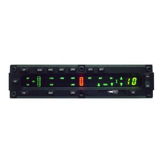
Mode Annunciator light level for all cockpit conditions. The Century 4000 Autopilot is activated with the Aircraft Master switch and operates in a low power state until the autopilot operation is desired. Mode selection is made by pushing the desired mode switch on the Mode Programmer. - Page 7 PREFLIGHT TEST SEQUENCE CENTURY 4000 PREFLIGHT PROCEDURES CENTURY 4000 AUTOTRIM NOTE During system functional check the system must be provided adequate D.C. voltage (12.0 VDC or 24 VDC min.) and instrument air (4.2 in. Hg. Min.). It is recommended that the engine be operated to provide the necessary power and that the aircraft be positioned in a level attitude, during the functional check.
- Page 8 PREFLIGHT TEST SEQUENCE CENTURY 4000 PREFLIGHT PROCEDURES CENTURY 4000 TRIM PROMPTER NOTE During system functional check the system must be provided adequate D.C. voltage (12.0 VDC or 24 VDC min.) and instrument air (4.2 in. Hg. Min.). It is recommended that the engine be operated to provide the necessary power and that the aircraft be positioned in a level attitude, during the functional check.
-
Page 9: Lateral Operating Modes
LATERAL OPERATING MODES HEADING - In HDG mode the autopilot will capture and hold the heading selected on the DG or HSI. HDG annunciator will illuminate. NAVIGATION - In NAV mode the autopilot has an automatic 45-degree VOR-LOC intercept angle. Selected angle intercepts are available when the system is equipped with NSD-360A, NSD-1000 or other HSI. -
Page 10: Heading Systems
HEADING SYSTEMS In systems equipped with a DG the autopilot heading bug must be set to match the selected VOR/LOC course when in NAV, APR, or REV modes. For loran or GPS tracking, set the heading bug to the “desired bearing” information. In systems equipped with and NSD-360A, NSD-1000 or other HSI instrument, the heading bug is disabled when in the NAV, APR, or REV modes. -
Page 11: Pitch Operating Modes (Trim Prompting)
Automatic 45-degree intercepts, selected angle intercepts, crosswind correction and tracking are as described in the APR mode accept that response to radio signals is reversed. NOTES When using an NSD-360A, NSD-1000 or other HSI always set the radio course pointer to the inbound front course localizer heading. -
Page 12: Review Of Interlocks And Failure Warnings
2 minutes until the large error is corrected. REVIEW OF INTERLOCKS AND FAILURE WARNINGS The Century 4000 Systems include a number of automatic interlocks that will prevent system operation or individual mode operation if the input information is not valid or if other pre-requisite conditions do not exist. -
Page 13: Yaw Damper Systems
The Yaw Damper is automatically engaged when the Century 4000 autopilot is engaged. The Yaw Damper may also be engaged through the YD switch on the Century 4000 if autopilot engagement is not desired. A YD light on the annunciator of the Century 4000 confirms the Yaw Damper is engaged. The... -
Page 14: Directional Gyro
NSD-360A, NSD-1000 AND OTHER HEADING SYSTEMS The Century 4000 autopilot may be optionally equipped with the Century Flight Systems, Inc. NSD-360A or NSD-1000 HSI. The explanation which follows will be based on Century’s HSI, however the principles will apply equally to the heading systems of other manufacturers provided the differences in design, features and concepts are ascertained and allowed for such as slaving, knob location, size, etc. - Page 15 (deviation from desired radio track) to provide precise intercept and track capability. NOTE The Century 4000 is capable of using radio information provided by a loran or GPS. There are several important factors to consider when using those units with the autopilot and HSI.
- Page 16 FLY RIGHT FLY UP FLY DOWN CENTURY 4000 FLIGHT DIRECTOR STEERING HORIZON SINGLE QUE With the addition of the Flight Director expansion, the pilot may choose to program a particular flight sequence and monitor autopilot maneuvering by observing the steering bar or he may switch the autopilot off and place himself in the control system loop by following commands of the steering bar.
-
Page 17: Century 4000 Operating Techniques
Localizer Back Course NOTE The Century 4000 autopilot is capable of tracking lateral information from a loran or GPS. Several factors in procedure and operation are important to remember. Adjust the course width (CDI sensitivity) of the loran or GPS to insure it is not too wide or too narrow (represented as nautical miles per dot). A course width too wide would cause the autopilot to S-turn back and forth along the desired track. -
Page 18: Dg Vor Navigation
VOR NAVIGATION... - Page 19 VOR Navigation STEP MODE REMARKS selected angle HDG/NAV intercept of up to 90° may be selected by setting the course arrow to the desired radial and the heading bug to the appropriate heading for the desired intercept. Press the HDG and NAV switches on the autopilot.
-
Page 20: Dg Vor Approach
VOR APPROACH... - Page 21 VOR Approach STEP MODE REMARKS approach usually begins from an ALT or enroute situation. As the VOR is neared, match the heading bug to ALT or course flown press the HDG switch. Set the course arrow for the inbound intermediate course segment.
- Page 22 VOR APPROACH...
- Page 23 VOR Approach STEP MODE REMARKS Turn the heading bug to the outbound procedure ALT or turn heading and press the HDG switch. Proceed outbound until sufficient time has elapsed ALT or assure proper interception. Lead aircraft through the procedure turn by moving ALT or the heading bug in the direction of the procedural...
- Page 24 VOR APPROACH...
- Page 25 VOR Approach STEP MODE REMARKS As the aircraft approaches the inbound course, the ALT or system will switch out of the dual mode and turn to the inbound course. After the on course turn, the system will correct for crosswind and enter into a “soft track”...
- Page 26 NOTES...
-
Page 27: Dg Localizer Approach
LOCALIZER APPROACH... - Page 28 LOCALIZER Approach STEP AP MODE REMARKS localizer approach begins with a ALT or transition from the enroute structure outer compass locator (LOM). The heading bug is used select desired heading. The aircraft’s altitude may be controlled by the modifier switch or through the use of the altitude mode.
- Page 29 LOCALIZER APPROACH...
- Page 30 LOCALIZER Approach STEP MODE REMARKS Proceed outbound in the procedure turn until ALT or sufficient time has elapsed assure proper interception. Lead the aircraft through procedure turn ALT or moving the heading bug in the direction of the turn. Continue lead ALT or aircraft through the turn.
- Page 31 LOCALIZER Approach...
- Page 32 LOCALIZER Approach STEP MODE REMARKS When the on course turn is initiated the HDG lamp ALT/GS will extinguish and the system will track localizer. After intercept, the system will correct for crosswind and enter into “soft track” mode. Internal radio gains and bank angles will be limited.
- Page 33 GS Arming & Capture...
- Page 34 ILS begins ALT or with the aircraft in the ALT mode or in the ATT mode with the aircraft on a closure attitude to the glide slope beam. Century 4000 autopilot system ALT or incorporates circuitry which anticipates when capture should occur.
- Page 35 NOTES...
-
Page 36: Dg Localizer Back Course
Localizer Back Course... - Page 37 Localizer Back Course STEP MODE REMARKS HDG/NAV The localizer back course approach begins with a ALT or transition from the enroute structure to an intercept with back course outbound. The inbound front course is set on the course arrow. Press the HDG and NAV switches simultaneously.
- Page 38 Localizer Back Course...
- Page 39 Localizer Back Course STEP MODE REMARKS As the aircraft continues to turn, set the heading bug ALT or to the inbound procedure turn heading. HDG/REV Press the HDG and REV switches simultaneously. ALT or The HDG and REV lamps should illuminate indicate the system is in a dual mode.
- Page 40 NOTES...
- Page 41 VOR Navigation...
- Page 42 VOR Navigation Directional Gyro . Remarks Step 1. NAV/ATT or ALT. A 45° intercept to a selected radial is accomplished by setting the OBS to the desired radial and turning the heading bug to that same degree and then pressing the NAV mode on the autopilot.
- Page 43 VOR APPROACH...
- Page 44 VOR Approach Step 1. NAV/ATT or ALT. The VOR approach usually begins from an enroute situation. The heading bug and the OBS are set to the same degree radial. The autopilot is providing crosswind correction to track the desired radial. Step 2.
- Page 45 VOR APPROACH...
- Page 46 VOR Approach Step 6. HDG/ATT or ALT. Proceed outbound until sufficient time as elapsed before starting the turn inbound. Step 7. HDG/ATT or ALT. Lead the aircraft through the procedure turn by moving the heading bug. Step 8. HDG/ATT or ALT.
- Page 47 NOTES...
- Page 48 Localizer Approach...
- Page 49 Localizer Approach Step 1. HDG/ATT or ALT. The localizer or ILS approach begins with a transition from enroute structure to the outer compass locator (LOM). The heading bug is used to select the desired heading. aircraft’s attitude may be controlled by the modifier switch or through the use of the altitude mode.
- Page 50 Localizer Approach...
- Page 51 Localizer Approach Step 6. HDG/ATT or ALT. Lead the aircraft through the procedure turn by moving the heading bug in the direction of the turn. Step 7. HDG/ATT or ALT. Continue to lead the aircraft through the turn. Step 8. APR/ALT. Turn the heading bug to the inbound front course of the ILS and press the...
- Page 52 Localizer Approach...
- Page 53 Localizer Back Course...
- Page 54 Localizer Back Course Step 1. HDG/ATT or ALT. The localizer back course approach begins with a transition from an enroute structure to intercept the back course outbound. An alternate method would be to set the inbound front course with the heading bug and press the APR switch to set up a 45°...
- Page 55 Localizer Back Course...
- Page 56 Localizer Back Course Step 6. REV/ATT or ALT. As the aircraft continues to turn, set the heading bug to the inbound procedure turn heading. Press the REV switch. The autopilot will set up a 45° intercept. Step 7. REV/ATT. After the on course turn is completed, the system will enter the “soft track”...
-
Page 57: Maintenance
We have listed several items below to assist you in monitoring you system maintenance. 1. Gyro Filters - The gyros used with the Century 4000 are precision devices whose performance and service life are in part dependent upon the quality of the air supply. Poor air quality can significantly reduce gyro life (to hours) and performance by contaminating bearings. -
Page 58: Warranty
Effective: July 4, 1975 LIMITED WARRANTY CENTURY FLIGHT SYSTEMS INC. Each new Century Flight Systems Inc. Autopilot or HSI is warranted by the manufacturer to be free from defects in material and workmanship under normal use, subject to the following conditions: 1.