Advertisement
Quick Links
48
1.890
48
1.890
Product types
Product name
Time range
9.999 s (0.001 s~)
99.99 s (0.01 s~)
999.9 s (0.1 s~)
LT4H-L
9999 s (1 s~)
digital timer
99 min 59 s (1 s~)
999.9 min (0.1 min~)
99 h 59 min (1 min~)
999.9 h (0.1 h~)
Option
DIN48 protective cover (soft type)
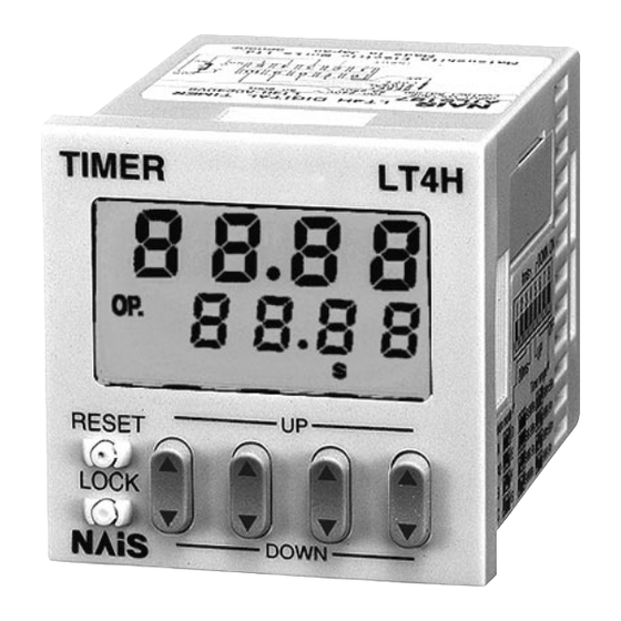
Part names
Time delay indicator
Controlled output indicator
Reset indicator
Lock indicator
Reset switch
Lock switch
DIN 48 SIZE
DIGITAL TIMER
UL File No.: E122222
C-UL File No.: E122222
Features
1. Economically priced in anticipation
of market needs.
• Economically priced to provide
excellent cost performance.
2. Display is a bright reflective-type
LCD.
64.5
3. Inherits all of the characteristics of
2.539
the LT4H digital timer.
mm
inch
• Seesaw switches ensure easy
operation.
• IP66 environmental protection.
• Shortened body (70.1 mm
underhead).
Operating mode
Power ON delay (1)
Power ON delay (2)
Signal ON delay
Signal OFF delay
Pulse One-shot
Pulse ON-delay
Signal Flicker
Totalizing ON-delay
(8 modes)
TIMER
LT4H
O P.
R S T
LO C K
h
m
s
UP
RESET
LOCK
DOWN
2.760 inch
Output
Operating voltage
100 to 240 V AC
Relay
24 V AC/DC
(1 c)
12 to 24 V DC
100 to 240 V AC
Transistor
24 V AC/DC
(1 a)
12 to 24 V DC
For the LT4H Series
(Countdown time display)
Elapsed time display
Set time display
Time units display
Up keys
Down keys
LT4H-L
Timers
4. UL, C-UL rating approved. CE
compliant.
5. Simultaneous release of DIN48
protective cover (soft type).
• Provides protection for surface and
buttons in dusty environments and from
dirty hands and gloves.
Power down
Terminal type
insurance
LT4HL8-AC240V
LT4HL8-AC24V
LT4HL8-DC24V
Available
8 pins
LT4HLT8-AC240V
LT4HLT8-AC24V
LT4HLT8-DC24V
N-TC-48-1
1
2
3
4
5
6
7
8
Part number
DIP switches
1
Advertisement

Summary of Contents for NAiS LT4H-L
- Page 1 LT4H-L DIN 48 SIZE DIGITAL TIMER Timers UL File No.: E122222 C-UL File No.: E122222 Features 1. Economically priced in anticipation 4. UL, C-UL rating approved. CE of market needs. compliant. 1.890 • Economically priced to provide 5. Simultaneous release of DIN48 excellent cost performance.
-
Page 2: Specifications
LT4H-L Specifications Type Ralay output type Transistor output type Item AC type, AC/DC type DC type AC type, AC/DC type DC type Rated operating voltage 100 to 240 V AC, 24 V AC/DC 12 to 24 V DC 100 to 240 V AC, 24 V AC/DC... - Page 3 LT4H-L Dimensions (units: mm inch) Tolerance: ±1.0 ±.039 • LT4H-L digital timer Embedded installation/front panel installation 55.6 14.5 1.890 .217 2.189 .571 TIMER LT4H 44.5 1.752 LOCK RESET LOCK DOWN .295 • Dimensions for embedded installation (with adapter installed) Installation panel...
- Page 4 LT4H-L Setting the operation mode, time range, and time Setting procedure 1) Setting the operation mode and time range Set the operation mode and time range with the DIP switches on the side of the timer. Table 1: Setting the operation mode...
-
Page 5: Operation Mode
LT4H-L Operation mode T: Set time t1, t2, t3, ta<T Operation type Explanation Time chart • Set the operation mode section of the DIP switches (no.’s 1, 2, and 3) on the side of the timer as shown. • Clears elapsed time value and starts time delay at power ON. - Page 6 LT4H-L T: Set time t1, t2, t3, ta<T Operation type Explanation Time chart • Set the operation mode section of the DIP switches (no.’s 1, 2, and 3) on the side of the timer as shown. • Clears elapsed time value at power ON.
- Page 7 PRECAUTIONS IN USING THE LT4H-L [When the impedance is 0 Ω, the current 1. Terminal wiring (Fig. B) 1) When wiring the terminals, refer to the coming from the start input and stop Input contact point or transistor terminal layout and wiring diagrams and...
- Page 8 PRECAUTIONS IN USING THE LT4H SERIES 4) The input signal is applied by the 6. Conditions of usage 5) When connecting the operating power shorting of each input terminal with the 1) Avoid locations subject to flammable supply, make sure that no leakage common terminal.
-
Page 9: Mounting Parts
DIN SIZE TIMERS COMMON OPTIONS Terminal sockets (Unit: mm inch, Tolerance: ±1 ±.039) Terminal wiring Appearance Dimensions Mounting hole dimensions (Top view) • DIN rail socket (8-pin) .945 .748 1.969 1.575 1.969 2-4.5 dia. 2-.177 dia. .945 2-M4 2-M.157 2.756 screw holes 35.3 ±0.1... -
Page 10: Installations
INSTALLATIONS Installations 1. Surface mount (Tighten the two screws with uniform Guideline values for dimension A when 1) Put the terminal socket on the board force and make sure that there is no installing n units in sequence are as directly or put it on the DIN rail (Fig. - Page 12 Automation Controls Company Head Office: 1048, Kadoma, Kadoma-shi, Osaka 571-8686, Japan Telephone: Japan (81) Osaka (06) 6908-1050 Facsimile: Japan (81) Osaka (06) 6908-5781 http://www.nais-e.com/ COPYRIGHT © 2001 All Rights Reserved ARCT1B188E 200112-1.5YT Specifications are subject to change without notice. Printed in Japan.