Fujitsu AUXG24KVLA Design & Technical Manual
Hide thumbs
Also See for AUXG24KVLA:
- Service manual (36 pages) ,
- Design & technical manual (229 pages) ,
- Service instruction (92 pages)

Related Manuals for Fujitsu AUXG24KVLA


Summary of Contents for Fujitsu AUXG24KVLA
- Page 1 AIR CONDITIONER Cassette type DESIGN & TECHNICAL MANUAL INDOOR AUXG24KVLA OUTDOOR AOYG24KATA DR_AU031EF_01 2019.08.23...
- Page 2 • Product specifications and design are subject to change without notice for future improvement. • For further details, please check with our authorized dealer. Trademarks ™ FGLair is trademark of Fujitsu General Limited in the United States, other countries or both. ™ Google Play is trademark of Google Inc. ®...
-
Page 3: Table Of Contents
CONTENTS Part 1. INDOOR UNIT................1 1. Specifications....................2 2. Dimensions....................4 2-1. Model: AUXG24KVLA......................4 2-2. Installation space requirement ..................5 3. Wiring diagram ....................6 3-1. Model: AUXG24KVLA......................6 4. Capacity table....................7 4-1. Cooling capacity.......................7 4-2. Heating capacity ......................7 5. Fan performance ...................8 5-1. Air velocity distributions....................8 5-2. - Page 4 CONTENTS (continued) Part 2. OUTDOOR UNIT..............33 1. Specifications....................34 2. Dimensions....................35 2-1. Model: AOYG24KATA ....................35 3. Installation space ..................36 3-1. Model: AOYG24KATA ....................36 4. Refrigerant circuit ..................39 4-1. Model: AOYG24KATA ....................39 5. Wiring diagrams ..................40 5-1. Model: AOYG24KATA ....................40 6. Capacity compensation rate for pipe length and height difference..41 6-1.
-
Page 5: Part 1. Indoor Unit
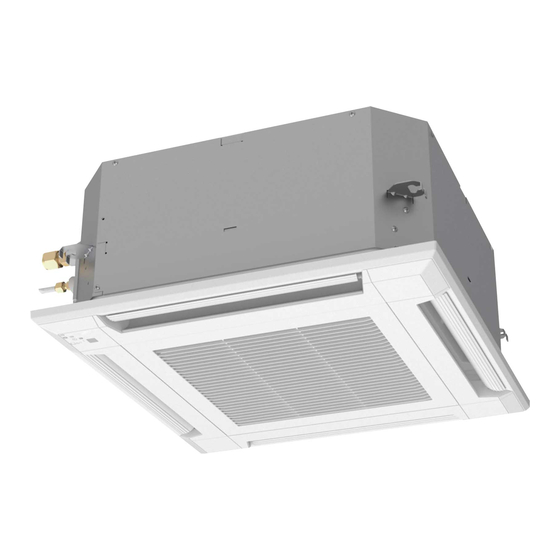
Part 1. INDOOR UNIT CASSETTE TYPE: AUXG24KVLA... -
Page 6: Specifications
1. Specifications Cassette Type Inverter heat pump Model name AUXG24KVLA Power supply 230 V ~ 50 Hz Power supply intake Outdoor unit Available voltage range 198—264 V 6.80 Rated Btu/h 23,200 Cooling 0.90—7.40 Min.—Max. Btu/h 3,100—25,200 Capacity 7.50 Rated Btu/h... - Page 7 Specifications for ErP Lot10 Model name AUXG24KVLA Cooling Energy efficiency class Heating (Average) Cooling 6.8 (35°C) Pdesign Heating (Average) 5.4 (-10°C) SEER Cooling 5.90 kWh/kWh SCOP Heating (Average) 3.80 Annual energy con- kWh/a sumption QHE (Average) 1,988 Cooling Sound power level...
-
Page 8: Dimensions
2. Dimensions 2-1. Model: AUXG24KVLA Unit: mm Grid type grille Hanging bolt position IR receiver Drain hose View A Ceiling Control Box View C View B a: Ceiling openings Cassette grille (Option [Grid type]) 580 to 610 - 4 - 2-1. -
Page 9: Installation Space Requirement
2-2. Installation space requirement Unit: mm Strong and durable ceiling or more 1,000 1,000 or more or more 1,800 or more Obstruction Floor Maximum height from floor to ceiling (Unit: mm) Standard 2,700 High ceiling 3,000 3-way direction setting: Unit: mm 100 or more* NOTES: •... -
Page 10: Wiring Diagram
3. Wiring diagram 3-1. Model: AUXG24KVLA - 6 - 3-1. Model: AUXG24KVLA 3. Wiring diagram... -
Page 11: Capacity Table
Airflow Rate (AFR): For cooling capacity: Total Capacity (TC), Sensible Heat Capacity (SHC), and Input Power (IP) For heating capacity: Total Capacity (TC) and Input Power (IP) 4-1. Cooling capacity ¢ Model: AUXG24KVLA Indoor temperature °CDB °CWB °CDB... -
Page 12: Fan Performance
5. Fan performance 5-1. Air velocity distributions ¢ Model: AUXG24KVLA (4-way air outlet) Fan speed Operation mode Ceiling mode Measuring conditions HIGH Standard Unit : m/s 0.25 Top view Vertical airflow direction louver: Upward 0.25 0.25 0.25 Unit : m/s... - Page 13 ¢ Model: AUXG24KVLA (3-way air outlet) Fan speed Operation mode Ceiling mode Measuring conditions HIGH Standard Unit : m/s 0.25 Top view Vertical airflow direction louver: Upward 0.25 0.25 Unit : m/s Side view Vertical airflow direction louver: Upward 0.25 0.25...
-
Page 14: Airflow
5-2. Airflow ¢ Model: AUXG24KVLA (Standard ceiling mode) Cooling Fan speed Airflow HIGH QUIET Heating Fan speed Airflow HIGH QUIET - 10 - 5-2. Airflow 5. Fan performance... - Page 15 ¢ Model: AUXG24KVLA (High ceiling mode) Cooling Fan speed Airflow 1,030 HIGH QUIET Heating Fan speed Airflow 1,000 HIGH QUIET - 11 - 5-2. Airflow 5. Fan performance...
-
Page 16: Operation Noise (Sound Pressure)
6. Operation noise (sound pressure) 6-1. Noise level curve Ceiling height Outlet directions Measuring conditions Standard 4-way air outlet ¢ Model: AUXG24KVLA Cooling Heating NC-65 NC-65 NC-60 NC-60 NC-55 NC-55 NC-50 NC-50 HIGH HIGH NC-45 NC-45 NC-40 NC-40... -
Page 17: Sound Level Check Point
6-2. Sound level check point Microphone 1.5 m Microphone - 13 - 6-2. Sound level check point 6. Operation noise (sound pressure) -
Page 18: Safety Devices
7. Safety devices Model Type of protection Protection form AUXG24KVLA Circuit protection Current fuse (PCB*) 250 V, 5 A 100 ± 10 °C Activate Fan motor stop Fan motor protection Thermal protection program 95 ± 10 °C Reset Fan motor restart... -
Page 19: External Input And Output
8. External input and output Indoor unit PCB CN47 (Ext. out) Terminal (Ext. in) External Input connect kit External input and output Connector Input select signal (Optional parts) Operation/Stop External input Terminal Dry contact Edge — Forced stop Operation status Error status External output CN47... -
Page 20: External Output
8-2. External output Use an external output cable with appropriate external dimension, depending on the number of ca- bles to be installed. • A twisted pair cable (22AWG) should be used. Maximum length of cable is 25 m. • Output voltage: High DC 12 V ± 2 V, Low 0 V. •... -
Page 21: Combination Of External Input And Output
8-3. Combination of external input and output By combining the function setting of the indoor unit, you can select various combinations of func- tions. Combination examples of external input and output are as follows: External input External output Mode Function setting Terminal CN47 60—00... -
Page 22: Details Of Function
8-4. Details of function ¢ Control input function • When function setting is "Operation/Stop" mode 1 Function setting External input Input signal Command Off → On Operation 46—00 Terminal On → Off Stop Input Operation Indoor unit Stop Remote controller NOTES: •... - Page 23 • When function setting is "Operation/Stop" mode 2 Function setting External input Input signal Command Off → On Operation 46—03 Terminal On → Off Stop (R.C. disabled) Input Operation Indoor unit Stop (R.C. disabled) Remote controller NOTE: When "Operation/Stop" mode 2 function is used with forming a remote controller group, connect the same equipment to each indoor unit within the group.
- Page 24 ¢ Indoor unit fan operation status Function setting External output Output signal Command Low → High Fan run 60—10 CN47 High → Low Fan stop Output signal Condition The indoor unit fan is operating. Low → High The fan is stopped or during cold air prevention. During thermostat off when in dry mode operation.
-
Page 25: Function Settings
9. Function settings To adjust the functions of this product according to the installation environment, various types of function settings are available. NOTE: Incorrect settings can cause a product malfunction. 9-1. Function settings on indoor unit By using some components on the PCB, you can change the function settings. ¢... - Page 26 ¢ DIP switch setting • SW100: Remote controller address setting NOTE: Because this setting is normally done automatically when 2-core wired remote con- troller is installed, setting is unnecessary. Multiple indoor units can be operated by using one wired remote controller. Set the unit number of each indoor unit.
-
Page 27: Function Settings By Using Remote Controller
9-2. Function settings by using remote controller Some function settings can be changed on the remote controller. After confirming the setting proce- dure and the content of each function setting, select appropriate functions for your installation envi- ronment. ¢ Setting procedure by using remote controller Remote controller is not attached for this product. - Page 28 2) Ceiling height Select the appropriate ceiling height according to the place of installation. Function number Setting value Setting description Factory setting Standard ♦ High ceiling For the specific height for each setting value, refer to “Installation space” in Chapter 2. "Dimensions"...
- Page 29 5) Room temperature control for wired remote controller sensor Depending on the installed environment, correction of the wire remote temperature sensor may be required. Select the appropriate control setting according to the installed environment. To change this setting, set Function 42 to Both “01”. Ensure that the Thermo Sensor icon is displayed on the remote controller screen.
- Page 30 8) Remote controller custom code (Only for wireless remote controller) The indoor unit custom code can be changed. Select the appropriate custom code. Function number Setting value Setting description Factory setting ♦ 9) External input control "Operation/Stop" mode or "Forced stop" mode can be selected. Function number Setting value Setting description...
- Page 31 12) Switching functions for external output terminal Functions of the external output terminal can be switched. For details, refer to “External input and output”. Function number Setting value Setting description Factory setting Operation status ♦ 01—08 (Setting prohibited) Error status Indoor unit fan operation status External heater - 27 -...
-
Page 32: Accessories
10. Accessories 10-1. Model: AUXG24KVLA Part name Exterior Q’ty Part name Exterior Q’ty Operating manual Drain hose insulation Operating manual Hose band (CD-ROM) Coupler heat insulation Installation manual (large) Coupler heat insulation Template (Carton top) (small) M10 nut A Cable tie... -
Page 33: Optional Parts
11. Optional parts 11-1. Controllers Exterior Part name Model name Summary Easy finger touch operation with LCD Wired remote panel. Backlit LCD enables easy UTY-RNRYZ* controller operation in a dark room. Wire type: Non-polar 2-wire High visibility and easy operation. Room temperature can be accurately Wired remote controlled using the built-in thermo... -
Page 34: 11-2.Cassette Grille
Exterior Part name Model name Summary Wireless remote Unit control is performed by wireless UTY-LNTY controller remote controller. NOTE: Available functions may differ by the remote controller. For details, refer to the operation manual. 11-2. Cassette grille Exterior Part name Model name Summary This cassette grille can be installed... -
Page 35: 11-3.Others
11-3. Others Exterior Part name Model name Summary Use to connect with various peripheral External devices and air conditioner PCB. UTY-XWZXZG connect kit For control output port. Air outlet shutter Installed at the air outlet when 3- UTR-YDZB plate directions mode is performed. By attaching Fresh-air intake kit to the Fresh-air intake indoor unit, it can be taken in fresh air... - Page 36 - 32 - 11-3. Others 11. Optional parts...
-
Page 37: Part 2. Outdoor Unit
Part 2. OUTDOOR UNIT SINGLE TYPE: AOYG24KATA... -
Page 38: Specifications
1. Specifications Type Inverter heat pump Model name AOYG24KATA Power supply 230 V ~ 50 Hz Power supply intake Outdoor unit Available voltage range 198—264 V Starting current 10.0 Cooling 2,885 Airflow rate Heating 2,350 Type × Q'ty Propeller × 1 Motor output Cooling Sound pressure level *1... -
Page 39: Dimensions
2. Dimensions 2-1. Model: AOYG24KATA Unit: mm 4-M10 hole Pitch of bolts for installation Top view Side view Front view Side view Airflow Drain port Ø42 Bottom view Side view (Valve part) - 35 - 2-1. Model: AOYG24KATA 2. Dimensions... -
Page 40: Installation Space
3. Installation space 3-1. Model: AOYG24KATA ¢ Space requirement Provide sufficient installation space for product safety. CAUTION Keep the space shown in the installation examples. If the installation is not performed accordingly, it could cause a short circuit and result in a lack of operating performance. - Page 41 Multiple outdoor unit installation • Provide at least 250 mm of space between the outdoor units if multiple units are installed. • When routing the piping from the side of an outdoor unit, provide space for piping. • No more than 3 units must be installed side by side. When 3 units or more are arranged in a line, provide the space as shown in the following ex- ample “When an obstruction in the upper space:”.
- Page 42 Outdoor units installation in multi-row Unit: mm Single parallel unit arrangement Multiple parallel unit arrangement 100 or more 200 or more 1,000 or more 2,000 or more 200 or more 400 or more 500 or more 1,000 or more 200 or more 250 or more 1,000 or more...
-
Page 43: Refrigerant Circuit
4. Refrigerant circuit 4-1. Model: AOYG24KATA Heat exchanger 3-way (INDOOR) valve 2-way Muffler valve Muffler Pressure switch Strainer 4-way valve Expansion valve Accumulator Heat exchanger Strainer (OUTDOOR) Cooling Heating : Thermistor (Compressor temperature) : Thermistor (Discharge temperature) : Thermistor (Outdoor temperature) : Thermistor (Heat exchanger out temperature) : Thermistor (Heat exchanger middle temperature) : Thermistor (Room temperature) -
Page 44: Wiring Diagrams
5. Wiring diagrams 5-1. Model: AOYG24KATA - 40 - 5-1. Model: AOYG24KATA 5. Wiring diagrams... -
Page 45: Capacity Compensation Rate For Pipe Length And Height Difference
6. Capacity compensation rate for pipe length and height difference Height difference H Indoor unit is higher than outdoor unit Indoor unit is lower than outdoor unit Outdoor unit Indoor unit Outdoor unit Indoor unit Connection pipe Connection pipe 6-1. Model: AOYG24KATA NOTE: Values mentioned in the table are calculated based on the maximum capacity. -
Page 46: Additional Charge Calculation
7. Additional charge calculation 7-1. Model: AOYG24KATA Refrigerant type Refrigerant amount 1,250 ¢ Refrigerant charge Total pipe length 20 or less 25 (Max.) 20 g/m Additional charge amount - 42 - 7-1. Model: AOYG24KATA 7. Additional charge calculation... -
Page 47: Airflow
8. Airflow 8-1. Model: AOYG24KATA Cooling 2,885 1,698 Heating 2,350 1,383 - 43 - 8-1. Model: AOYG24KATA 8. Airflow... -
Page 48: Operation Noise (Sound Pressure)
9. Operation noise (sound pressure) 9-1. Noise level curve ¢ Model: AOYG24KATA Cooling Heating NC-65 NC-65 NC-60 NC-60 NC-55 NC-55 NC-50 NC-50 NC-45 NC-45 NC-40 NC-40 NC-35 NC-35 NC-30 NC-30 NC-25 NC-25 NC-20 NC-20 NC-15 NC-15 1,000 2,000 4,000 8,000 1,000... -
Page 49: Electrical Characteristics
10. Electrical characteristics Model name AOYG24KATA Voltage 230 ~ Power supply Frequency Max operating current *1 12.6 Starting current 10.0 Circuit breaker current Power cable Wiring spec. *2 Cross-sectional area Connection cable *3 Limited wiring length *1: Maximum current is the total current of the indoor unit and the outdoor unit. *2: Selected sample based on Japan Electrotechnical Standards and Codes Committee E0005. -
Page 50: Safety Devices
11. Safety devices Model Type of Protection form protection AOYG24KATA 250 V, 25 A Circuit Current fuse 250 V, 5 A protection (Main PCB) 250 V, 3.15 A 125 ±10 °C Activate Fan motor stop Fan motor Thermal protection program protection 120 ±10°C Reset... -
Page 51: Accessories
12. Accessories 12-1. Model: AOYG24KATA Part name Exterior Q’ty Part name Exterior Q’ty Installation manual Drain pipe - 47 - 12-1. Model: AOYG24KATA 12. Accessories...